CTRRS-161.000
Stand 08.2007 JD 5 21 378 00
Elektronischer Temperaturregler
Electronic Temperature Controller
1. Anwendung
Dieser Temperaturregler wurde speziell zur Ansteuerung von Peltiermodulen, zum
Heizen oder Kühlen von Schaltschränken, Fahrkarten- und Geldautomaten oder zur
Heiz-/Kühlmeldungen bzw. Anforderungen entwickelt. Für andere, vom Hersteller
nicht vorherzusehende Einsatzgebiete, sind die dort gültigen Sicherheitsvorschriften
zu beachten. Eignung hierfür siehe Punkt 8. Gewährleistung.
This temperature controller has been specially devised for the triggering of Peltier
modules, which are usually applied in connection with the heating or cooling control
operations performed in switch cabinets, ticket machines or cash dispensers or for
the emission of heating and cooling messages or requests. Regarding other applica-
tions not to be foreseen by the manufacturer of this device, the safety standards
concerning these applications need to be followed and adhered to. Regarding the
aptitude of the device for any such other application, please refer to section 8 herein
(Warranty).
1. Application
2. Funktion
Der CTRRS misst mit einem internen Sensor die Lufttemperatur im Schaltschrank
und aktiviert bei Unter- oder Überschreiten des eingestellten Sollwertes die Heizung
oder Kühlung. Um ein permanentes Heizen oder Kühlen bei Ausfall der Regler-
Betriebsspannung zu vermeiden, ist die Betriebs- und die Schaltspannung intern mit-
einander verbunden und der Schaltausgang potentialbehaftet.
Achtung: Der Regler kann nur für eine Betriebsart Heizen oder Kühlen eingesetzt
werden. Der Wechselkontakt ist nicht dafür vorgesehen, bei Peltierelemente durch
Umkehr der Stromrichtung Heizen und Kühlen zu realisieren.
The CTRRS is equipped with an internal sensor that meters the air temperature in the
switch cabinet or in other devices that need to be controlled. This sensor triggers,
upon the lower deviation or transgression of the preadjusted set value, the activation
of the required heating or cooling operations. With this system, both the operating
and the switching voltage have been connected internally with each other and the
switching output is, in order to prevent the system from the continued heating or
cooling in the event of a breakdown of the voltage used for the operation of the
device, a non-isolated one.
Caution: The device can be applied for one operating mode only, videlicet either “hea-
ting” or “cooling”. The changeover contact realised with this device is not suited for the
triggering of both operating modes through the reversal of the current flow direction.
2. Functional description
3. Installation / Montage
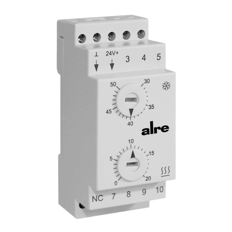
Die Montage des Reglers erfolgt auf einer 35 mm DIN-Normschiene. Hierzu wird der
Regler mit den oberen Haken eingehängt und anschließend durch Aufdrücken auf die
Normschiene eingeschnappt. Zum Abnehmen des Reglers von der Normschiene wird
dieser zuerst nach unten gezogen und nach vorne ausgehängt. Vorzugsweise sollte
der Regler auf eine waagerechte Normschiene mit den Klemmen nach unten aufge-
schnappt werden, andere Einbaulagen sind jedoch ebenfalls möglich. Der CTRRS
verfügt über einen internen Sensor. Um die tatsächliche Innentemperatur des Schalt-
schranks zu erfassen, darf er nicht direkt Kälte- oder Wärmequellen ausgesetzt wer-
den, es sei denn, es handelt sich um die zu schützende Baugruppe. Zur Montage auf
einer Blechwand oder einem Profilrahmen wird das Montageset JZ-13 (siehe Punkt
5.) verwendet. Nach der Montage ist der Regler wie im Anschluss-Schaltbild (Punkt
6.) zu verdrahten.
Achtung! Die Verdrahtung ist genau einzuhalten. Der Regler steuert ein Peltierele-
ment an, bei dem die Stromrichtung über die Funktion „Heizen“ oder „Kühlen“ ent-
scheidet. Durch Verwechslung der elektrischen Anschlüsse am Peltierelement kommt
es zur Wirkrichtungsumkehr und somit zur Blockierung der Regelung. Bei Anschluss
an den Kühlausgang würde permanent geheizt, bei Anschluss an den Heizausgang
permanent gekühlt werden. Nach der Installation ist daher die korrekte Wirkrichtung
und einwandfreie Funktion der Regelung zu überprüfen.
Die Einstellung des Schaltpunktes wird mit einem Schlitzschraubendreher vorgenom-
men. Zum Schutz gegen eigenständiges Verstellen des Reglers ist der Knopf in ra-
stender Form ausgeführt.
The controller is provided for installation on a 35 mm DIN standard rail. To install it,
the controller must fist be hung up on the rail using the upper hooks provided for
this purpose. After that, it can be snapped onto the standard rail by pressing against
the device. The controller can be removed again by pulling it downward first and un-
hooking it then in forward direction. The controller should, preferably, be snapped
onto a standard rail that is in horizontal position. When doing so, the snap-on clips
should point in downward direction. The device can nevertheless be installed in other
positions too. The CTRRS has been equipped with an internal sensor. This sensor
must, in order to be able to detect the temperature that actually prevails inside the
switch cabinet or other device that needs to be controlled, not be exposed to direct
cold or heat sources, except however, if this cold or heat source was the module or
sub-assembly that needs to be protected. The accessory kit JZ-13 (see section 5.)
will be required for the installation of the device on a sheet metal wall or on a profiled
frame. Once the installation is over, the device needs to be wired as shown in the
connection diagram (section 6.).
Caution! The wiring layout must be strictly realised as indicated! The device has been
designed for the triggering and control of a Peltier element inside of which the direc-
tion of the current that flows through its circuit decides about whether or not
“heating” or “cooling” is activated. The confusion of the electrical connections at the
Peltier element will result in a reversal of the actually required function (i.e. heating
instead of cooling and vice versa) and the controller will no longer be able to fulfil its
tasks. If connecting the electrical connections at the Peltier element erroneously to
the cooling instead to the heating output, permanent heating would be the conse-
quence. Likewise, permanent cooling would be the result when connecting
erroneously to the heating output. After completion of the electrical installation, the
overall system must therefore be checked for the correct direction of operation and
the flawless execution of the control operations to be performed.
The setting of the switch point can be effected by means of a slot screwdriver. The
locking design of the control knob prevents from an inadvertent or independent
misadjustment of the device.
3. Mounting / installation
Sicherheitshinweis Safety information
No persons other than expert electricians only must open this device in due compli-
ance with the wiring diagram shown in the housing cover / on the housing / repre-
sented in the corresponding operating instructions. All expert electricians committed
to the execution of any such works must comply with the relevant safety regulations
currently operative and in force. Caution! The operation of the controller in the vicinity
of other devices that do not comply with the EMC directives may affect its functions.
The company charged with the installation of the device must, after the completion of
the installation works, instruct the user of the control system into its functions and in
how to operate it correctly. These operating instructions must be kept at a place that
can be accessed freely by the operating and/or servicing personnel in charge.
Dieses Gerät darf nur durch eine Elektrofachkraft geöffnet und gemäß dem entspre-
chenden Schaltbild im Gehäusedeckel / auf dem Gehäuse / in der Bedienungsan-
leitung installiert werden. Dabei sind die bestehenden Sicherheitsvorschriften zu
beachten. Achtung! Der Betrieb in der Nähe von Geräten, welche nicht den EMV-
Richtlinien entsprechen, kann zur Beeinflussung der Gerätefunktionen führen. Nach
der Installation ist der Betreiber, durch die ausführende Installationsfirma, in die
Funktion und Bedienung der Regelung einzuweisen. Die Bedienungsanleitung muss
für Bedien- und Wartungspersonal an frei zugänglicher Stelle aufbewahrt werden.
DGB
1. Oben einhängen / Hook up at the top
2. Unten einschnappen / Snap on below
1
2
1. Nach unten ziehen / Pull downward
2. Schräg aushängen / Unhook in inclined manner
1
2

