manuals.online logo
Brands
  1. Home
  2. •
  3. Brands
  4. •
  5. alre
  6. •
  7. Controllers
  8. •
  9. alre KTRBUu217.456 User manual

alre KTRBUu217.456 User manual

KTRBUu217.456
Stand 05.2022 1 5 22 053 01
Montageanleitung
BACnet Raumregler mit Display
Sicherheitshinweise!
Dieses Gerät darf nur durch eine Elektrofachkraft und gemäß dem
entsprechenden Anschlussschaltbild in der Bedienungsanleitung
installiert werden. Dabei sind die bestehenden Sicherheitsvorschriften
zu beachten.
Die Montage / Demontage darf nur im spannungsfreien Zustand
erfolgen.
Fehlersuche und Beseitigung ist nur durch eine Elektrofachkraft
durchzuführen.
Defekte Teile nur durch Originalteile vom Hersteller ersetzen.
Staub und Schmutz vorsichtig mit einem trockenen, lösungs-
mittelfreien und weichen Tuch von der Gehäuseoberfläche entfernen.
1. Anwendung
Der alre BACnet Raumregler mit grafischem Display wurde speziell für den
zeitabhängigen Heiz- und Kühlbetrieb in 2- oder 4-Rohr-Systemen entwickelt.
Der Regler kann in vielfältigen Bereichen eingesetzt und angewendet werden,
wie zum Beispiel in Hotel, Wohn-, Büro- und Geschäftsräumen sowie
Krankenhäuser und Schulen.
Die Kommunikation erfolgt mittels BACnet gemäß DIN EN ISO 16464-5
mit dem Netzwerkprotokoll BACnet MS/TP. Damit ist der Raumregler mit
allen gängigen Systemen der Gebäudeautomation kompatibel. Der Regler
entspricht dem BACnet-Profil “B-AAC“ (BACnet Advanced Application
Controller).
Mit den vordefinierten Applikationen sind vielfältige Anwendungen für
Raumtemperierungen in der Raumautomation abgedeckt.
Safety notices!
This device may only be installed by an electrician in accordance with
the corresponding connection diagram in the operating instructions.
The applicable safety regulations should be observed.
Mounting / removal may only be undertaken when de-energised.
Troubleshooting and fault rectification should only be carried out by
an electrician.
Defective parts can only be replaced with original factory parts.
Carefully remove dust and dirt from the housing surface using a dry,
solvent-free and soft cloth.
1. Function
The alre BACnet room controller with graphic display is suited to time-based
heating and cooling operation in 2- or 4-pipe systems. The controller can be
used in various sectors, such as hotels, apartments, offices and business
premises as well as hospitals and schools.
The unit communicates using BACnet in accordance with DIN EN ISO 16464-
5 with the network protocol BACnet MS/TP. The room controller is therefore
compatible with all common building automation systems. The controller has
a “B-AAC” BACnet profile (BACnet Advanced Application Controller).
Most uses of room automation are covered by the predefined applications for
room temperature control.
Assembly instruction
BACnet room controller with display
2. Technische Daten
Betriebsspannung: 230 VAC, 50Hz
Elektrischer Anschluss: Schraub-Steckklemmen
netzspannungsseitig 0,75 – 2,5 mm²
kleinspannungsseitig 0,08 – 1,5 mm²
Schaltkontakt: 2 Relais / Schließer, Typ 1C
Schaltvermögen O1/O2: je 3 (0,5) A / 230 VAC,
(max. 5 Ventilantriebe je Ausgang)
Analoger Ausgang O3: 0-10V (SELV), max. 5mA zur
Lüfter- oder Ventilansteuerung
Einstellbereiche: 5 … 30°C Heizen
18 … 40°C Kühlen
Schutzart: IP 30
Schutzklasse: II, nach entsprechender Montage
zul. Luftfeuchte: max. 95%, nicht kondensierend
Umgebungstemperatur: 0 … 40°C
Anzeige: beleuchtetes, grafisches Display
Montage / Befestigung: in Unterputzdose, in nahezu alle
Flächenschalterprogramme adaptierbar
Softwareklasse: A
Bemessungsstoßspannung: 4000 V
Verschmutzungsgrad: 2
Energieeffizienzklasse: I (Beitrag zur jahreszeitbedingten
Raumheizungs -Energieeffizienz 1 %)
2. Technical data
Operating voltage: 230 VAC, 50Hz
Electrical connection: Screw plug-in terminals
mains voltage supply 0.75 – 2.5 mm²
low voltage supply 0.08 – 1.5 mm²
Switching contact: 2 relays (make contact), type 1C
Switching capacity O1/O2: 3 (0.5) A in each case / 230 VAC
(max. 5 valve drives per output)
Analogue output O3:
0-10V (SELV), max. 5 mA for fan triggering or
valve control
Setting range: 5 … 30°C (heating)
18 … 40°C (cooling)
Degree of protection: IP 30
Protection class: II, following appropriate mounting
Permissible humidity: max. 95%, non-condensing
Permissible ambient temp.: 0 … 40°C
Display: illuminated, graphic display
Installation / mounting: flush-mounted, adaptable in almost all
panel switch programmes
Software class: A
Rated impulse voltage: 4000 V
Degree of pollution: 2
Energy efficiency class: I (contribution to seasonal space heating
energy efficiency 1 %)
3. Montage / Anschluss
Die Montage und der elektrische Anschluss dürfen nur im
spannungsfreien Zustand erfolgen.
Das Gerät ist zur Montage in die Unterputzdose bestimmt und darf nicht
direkt Wärme- oder Kältequellen ausgesetzt werden. Es ist darauf zu achten,
dass das Gerät auch rückseitig keiner Fremderwärmung oder -kühlung, z.B.
bei Hohlwänden durch Zugluft oder Steigleitungen, ausgesetzt wird. Der
Tragring ist auf die Tapete / den Wandbelag zu montieren. Das Gerät mit dem
50 x 50 mm Gehäusedeckel ist mittels Zwischenrahmen der Schalterhersteller
nach DIN 49075 in nahezu alle Schalterprogramme integrierbar. Das Gerät
mit dem 55 x 55 mm bzw. 60 x 60 mm Gehäusedeckel ist ebenfalls für
diverse Schalterprogramme geeignet. Bei Mehrfachrahmen ist das Gerät
immer an unterster Stelle zu montieren.
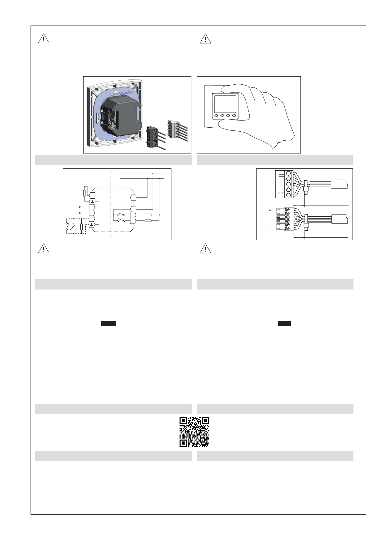
Der elektrische Anschluss erfolgt gemäß Anschluss-Schaltbild Punkt 4. /
Abb.3. Hierzu können die Steckklemmen komfortabel vorverdrahtet und bei
der Montage in die Unterputzdose mit dem Gerät verbunden werden (siehe
Abb. 1). Zum Öffnen des Gerätes oben und unten am Gehäusedeckel greifen
und ziehen, wie in Abb. 2 dargestellt.
3. Installation / connection
Mounting and the electric connection may only be undertaken when
de-energised.
The device is designed for installation in the flush-mounted box and may not
be directly exposed to sources of heat or cold. It must be ensured that the
device is also not exposed to external sources of heat or cold from behind
i.e. with hollow walls through drafts or standpipes. The bearer ring is to be
mounted onto the wallpaper / wall covering. The device with a 50 x 50 mm
housing cover can be integrated in almost all light switch programmes when
the switch manufacturer’s intermediate frame according to DIN 49075 is
used. The device with a 55 x 55 mm or 60 x 60 mm housing cover is also
suitable for different switch programmes. The device must always be installed
at the lowest position when it comes to multi-frames.
Electrical connection is undertaken in accordance with the connection wiring
diagram in Point 4. / Fig. 3. For this purpose, the plug-in terminals may be
conveniently prewired and connected with the device in the flush-mounted
box during mounting (see Fig. 1). To open the device, catch hold of the top
and bottom of the housing cover and remove it as depicted in Fig. 2.
Hinweise zur Anleitung
Lesen Sie diese Anleitung sorgfältig, bevor Sie das Gerät installieren und
in Betrieb nehmen. Die Bedienungsanleitung muss für Bediener und
Wartungspersonal an frei zugänglicher Stelle aufbewahrt werden.
Folgende Symbole werden in dieser Anleitung verwendet:
Warnung vor elektrischer
Spannung Wichtige Information
Notes relating to instructions
Read these instructions carefully before installing and commissioning
the device. The operating instructions must be stored somewhere freely
accessible to operator and maintenance staff.
The following symbols are used in these instructions:
Warning of electric voltage Important information
2
Fühler-/Kontakt-/Datenleitungen nicht parallel zu netzspannungs-
führenden Leitungen verlegen.
Der KTRBUu217.456 besitzt keine Line Termination
(Leitungsabschluss). Ist das Gerät der erste oder letzte Teilnehmer
am MS/TP-Bus, muss ein Abschlusswiderstand (120 Ω) zwischen
den Klemmen D+ und D- installiert werden.
Informationen zur Konfiguration und Bedienung dieses Gerätes siehe
Punkt 6.
Ensure that the sensor/contact/data cables are not laid parallel to
mains voltage cables.
This device has no End-of-Line termination. If the KTRBUu217.456 is
the first or last device on the MS/TP bus, a termination resistor (120
Ω) must be applied across terminals D+ and D-.
Information on the configuration and operation of this device see
Point 6.
RS485
NTC
TPS
max. 5mA
3(0,5)A
0—10V
SELV 230V~50Hz
L
N
O2
O1
L
N
O3
D−
D+
I1
Abb. 1
Fig. 1
Abb. 2
Fig. 2
4. Anschluss-Schaltbild 4. Connection wiring diagram
Wichtiger Hinweis! Die Einzeladern der Netzspannungsversorgung
und der Sensor-/Kontakt-/Datenleitungen sind durch Setzen je eines
Kabelbinders gegen Verlagerung zu sichern (siehe Abb. 4). Hierbei ist
auf einen möglichst kurzen Abstand, maximal jedoch 15 mm,
zwischen Kabelbinder und Netzanschluss bzw. Sensor-/
Kontaktklemmen zu achten.
Kabelschirm nicht am Gerät anschließen.
Important note! The single conductors of the mains power and
sensor-/contact-/data cables are to be separately secured against
shifting using cable ties (see Fig. 4). In doing so, the shortest possible
distance between the cable ties and the mains connection and/or
sensor-/contact terminals must be maintained, this should not
exceed a maximum of 15 mm.
Do not connect the cable shield to the device.
6. Weitere Informationen 6. Further information
Das Handbuch zum BACnet Raumregler
finden Sie im Internet unter
https://alre.de/de/service/download/
The manual of BACnet room controller can
be found at
https://alre.de/de/service/download/
7. Gewährleistung
Die angegebenen technischen Daten wurden durch uns jeweils in einem
dafür geeigneten Prüf- und Testumfeld (hierzu geben wir auf Anfrage
Auskunft) ermittelt und stellen nur auf dieser Grundlage die vereinbarte
Beschaffenheit dar. Die Prüfung der Eignung für den vom Auftraggeber /
Kunden vorgesehenen Verwendungszweck oder den Einsatz unter den
konkreten Gebrauchsbedingungen obliegt dem Auftraggeber / Kunden;
hierfür übernehmen wir keine Gewährleistung. Änderungen vorbehalten.
7. Guarantee
We determined the technical data provided in an inspection and test
environment suited to this task (we are happy to provide details on request)
and this data only presents the agreed properties on this basis. The
purchaser / customer is responsible for checking the suitability of the use or
usage intended by the purchaser / customer under the specific conditions
of use; we do not accept any liability for this. We reserve the right to
amendments.
ALRE-IT Regeltechnik GmbH · Richard-Tauber-Damm 10 · D-12277 Berlin
Tel.: +49(0)30/399 84-0 · Fax: +49(0)30/391 70 05 · [email protected] · www.alre.de
Abb. 3
Fig. 3
Abb. 4
Fig. 4
O1
O2
L
N
O3
D–
D+
I1
max. 15 mm
max. 15 mm
Klemme Netzanschluss
Mains voltage terminal
Klemme Anschluss Sensor-/
Kontakt-/Datenleitungen SELV
Terminal sensor-/contact-/data line
connection SELV
5. Erstinbetriebnahme 5. First start-up and commissioning
Bei der Erstinbetriebnahme werden automatisch folgende Einstellungen 5.1
BACnet und 5.2 Anlagenschema abgefragt:
5.1 BACnet
Konfiguration der MS/TP-Schnittstelle. Die hier notwendigen Einstellungen sind
vom Anlagenbetreiber vorgegeben. Erst nach korrekter Einrichtung ist das Gerät
über das Netzwerk erreichbar.
Dieser Punkt kann mit der Taste EndeEnde übersprungen und zu einem späteren
Zeitpunkt durchgeführt werden. Bis zur korrekten Einrichtung befindet sich
das Gerät im Offline-Modus (Regelbetrieb mit lokalen Einstellmöglichkeiten).
Weiterführende Informationen hierzu siehe Punkt 6.
5.2 Anlagenschema
Auswahl des Anlagenschemas. Abhängig vom gewähltem Anlagenschema
sind ggfs. weitere Einstellungen zu externen Sensoren/Kontakten, Ventiltypen
etc. möglich. Die hier notwendigen Einstellungen sind vom Anlagenbetreiber
vorgegeben. Weiterführende Informationen hierzu siehe Punkt 6.
Nach Auswahl des Anlagenschemas führt das Gerät einen Neustart durch.
5.3 Offline-Modus
Wurde die Kommunikationsschnittstelle noch nicht konfiguriert oder ist die
Verbindung zur GLT unterbrochen, führt das Gerät automatisch einen Regelbetrieb
mit eingeschränkten lokalen Einstellmöglichkeiten aus (Uhrzeit, Datum, Sollwerte,
Betriebsart, Reglereinstellungen).
Bei Wiederherstellung der Verbindung gelten wieder die Einstellungen über die GLT.
During initial commissioning, the following settings 5.1 BACnet and 5.2
System scheme are automatically requested:
5.1 BACnet
Configuration of the MS / TP interface. The settings required here are
specified by the operator. Only after the device has been correctly set up can
the device be reached via the network.
This item can be skipped with the key EndEnd and performed later. Until the
device has been set up correctly, the device is in offline mode (control mode
with local setting options). For further information, see point 6.
5.2 System scheme
Selection of the system scheme. Depending on the selected system scheme,
further settings to external sensors / contacts, valve types etc. may be
possible. The settings required here are specified by the operator. For further
information, see point 6.
After selecting the system scheme, the device reboots.
5.3 Offline mode
If the communication interface has not yet been configured or the connection
to the building control system is interrupted, the device automatically
performs a control mode with limited local setting options (time, date,
setpoints, operating mode, controller settings).
When the connection is restored, the settings via the building control system
apply again.

Other alre Controllers manuals

alre KTRTB-251.108 User manual

alre

alre KTRTB-251.108 User manual

alre FETR 101.700 User manual

alre

alre FETR 101.700 User manual

alre KR 80 Series User manual

alre

alre KR 80 Series User manual

alre KTRRB-117.128 User manual

alre

alre KTRRB-117.128 User manual

alre KTRRN-267.014 User manual

alre

alre KTRRN-267.014 User manual

alre KTBSB-112.000 User manual

alre

alre KTBSB-112.000 User manual

alre RFHSB-060.010 User manual

alre

alre RFHSB-060.010 User manual

alre KTRRB-042.211 User manual

alre

alre KTRRB-042.211 User manual

alre HTFRD Series User manual

alre

alre HTFRD Series User manual

alre KTRTB-211.108 User manual

alre

alre KTRTB-211.108 User manual

alre JDI-22 Instruction manual

alre

alre JDI-22 Instruction manual

alre CTRRS-161.000 User manual

alre

alre CTRRS-161.000 User manual

alre KTRRU-052.204 User manual

alre

alre KTRRU-052.204 User manual

Popular Controllers manuals by other brands

TouchWand ACWand installation manual

TouchWand

TouchWand ACWand installation manual

UPS ZINTO A Series user manual

UPS

UPS ZINTO A Series user manual

Epever iTracer-ND Series user manual

Epever

Epever iTracer-ND Series user manual

Unitronics Vision OPLC V1040-T20B user guide

Unitronics

Unitronics Vision OPLC V1040-T20B user guide

Ricoh RV5VH Applications manual

Ricoh

Ricoh RV5VH Applications manual

Siemens PS 307 6ES7307-1BA01-0AA0 operating instructions

Siemens

Siemens PS 307 6ES7307-1BA01-0AA0 operating instructions

Honeywell CIPer 30 installation instructions

Honeywell

Honeywell CIPer 30 installation instructions

WifiTrax Model Science WUFP-47 operating manual

WifiTrax Model Science

WifiTrax Model Science WUFP-47 operating manual

Harpo BraillePen 12 quick start

Harpo

Harpo BraillePen 12 quick start

Bühler technologies FF Series Brief instructions

Bühler technologies

Bühler technologies FF Series Brief instructions

Müller MDR-057 Operating and assembly instructions

Müller

Müller MDR-057 Operating and assembly instructions

RadioLink BYME-D instruction manual

RadioLink

RadioLink BYME-D instruction manual

ICS Tunnel Master Jr manual

ICS

ICS Tunnel Master Jr manual

Dwyer Instruments Series DH3 Digihelic Installation and operating instructions

Dwyer Instruments

Dwyer Instruments Series DH3 Digihelic Installation and operating instructions

Hiwin RC4 user manual

Hiwin

Hiwin RC4 user manual

HiModel ESC user guide

HiModel

HiModel ESC user guide

Sony MJ100 instruction manual

Sony

Sony MJ100 instruction manual

ComAp InteliDrive Lite Global Guide

ComAp

ComAp InteliDrive Lite Global Guide

manuals.online logo
manuals.online logoBrands
  • About & Mission
  • Contact us
  • Privacy Policy
  • Terms and Conditions

Copyright 2025 Manuals.Online. All Rights Reserved.