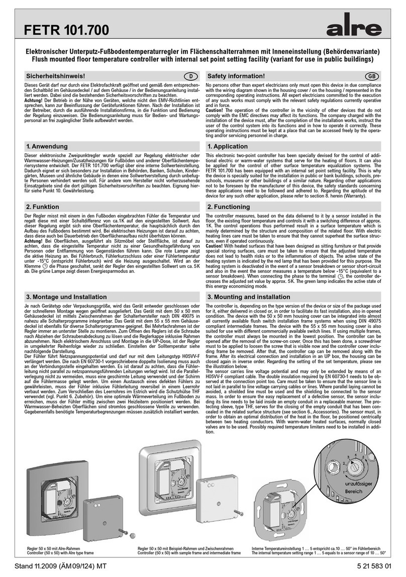
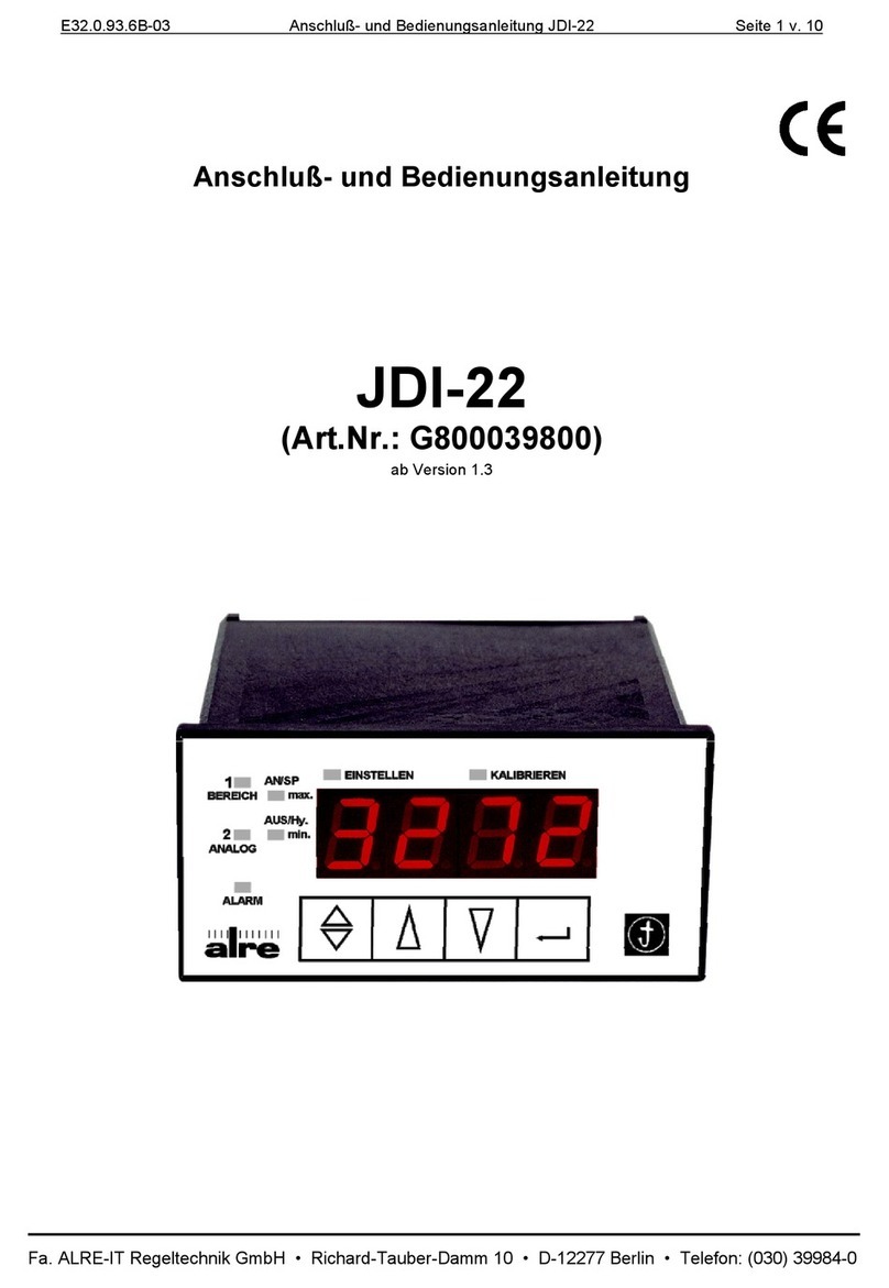
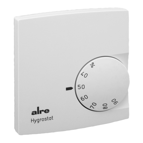
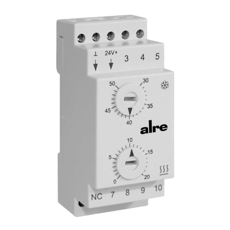
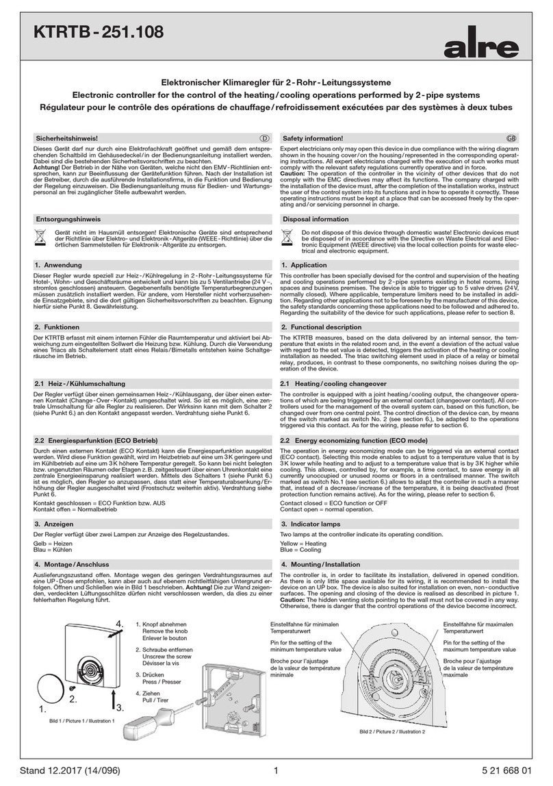
alre KR 80 Series User manual

Stand 12.2014 1 2 12 648 00
Dieses Gerät darf nur durch einen Elektro-Fachmann geöffnet und gemäß dem Schaltbild
im Gehäusedeckel / Bedienungsanleitung installiert werden. Dabei sind die bestehenden
Sicherheitsvorschriften zu beachten.
Anwendung
KR … Diese Gerätereihe wurde speziell entwickelt für den Einsatz in der Heiztechnik in
Kesselanlagen oder Speichern, Fernwärmeübergabestationen und Wärmeübertragungsan-
lagen.
LR … in der Lüftungstechnik als Zuluftüberwachung oder als Begrenzer von elektrischen
Heizregistern.
Funktion des Gerätes
TB (Temperaturbegrenzer) / Inneneinstellung, Außenrückstellung
TW (Temperaturwächter) / Inneneinstellung
TR (Temperaturregler) / Außeneinstellung
STB (Sicherheitstemperaturbegrenzer) / Inneneinstellung, Innenrückstellung
TB/TR/TW: Wird der eingestellte Temperatursollwert erreicht, schaltet der Kapillarfühler
den Mikroschalter und der Heizkontakt 1 – 2 öffnet. Der Heizkreis wird abgeschaltet. Der
Kühlkontakt 1 – 3 schließt und ist aktiv.
STB: Wird der Temperaturgrenzwert erreicht, öffnet der Heizkontakt 1 – 2. Der Heizkreis
wird abgeschaltet. Der Signalkontakt 1 – 3 schließt und ist aktiv. Nach Unterschreiten
des Temperaturgrenzwerts um ca. 20-25K kann der STB entriegelt werden.
Technische Daten
Regelbereich TR/TW: siehe Leistungsschild
Abschalttemperatur TB: einstellbar (siehe Leistungsschild)
Abschalttemperatur STB: fest 75°C oder 100°C (siehe Leistungsschild)
Schaltdifferenz
TR/TW: siehe Leistungsschild
TB: Handrückstellung nach Abkühlung um min. 8K
STB: Handrückstellung nach Abkühlung um min. 20K
Schaltvermögen
TR/TW/TB: 15(8)A 24 - 250V~, bei 24V~ min. 150 mA
STB: Heizkontakt 1-2 16(4)A 24 - 250V~,
bei 24V~ min. 500 mA
Signalkontakt 1-3 bei 250 V~ max. 500 mA,
bei 24 V~ min. 500 mA
Achtung! Wenn TR mit STB gekoppelt
Schaltvermögen Heizkontakt siehe STB,
Schaltvermögen Kühlkontakt siehe STB Signalkontakt
Kontaktart: TW = Typ 2.B
TB = Typ 2.B.H.V
TR = Typ 1.B
STB = Typ 2.B.H.K.P.V
Anschlussquerschnitt: 1,0 … 2,5 mm2
Schutzart: IP43 / optional IP54
max. Kopftemperatur: 80°C
max. Temperatur am Sensor
TR/TW/TB: Skalenendwert +15%
STB: 135°C
Zeitkonstante: ca. 50 Sek. mit Tauchrohr in bewegtem Wasser
Kontakte: potentialfreier Umschalter
Bulbe und Kapillare: Cu
Tauchhülse: Ms vernickelt oder V4A
Schutzwendel: Stahl vernickelt
Einbaubedingungen
Bei Reglern mit Außeneinstellung muß zuerst der Temperatur-Einstellknopf abgezo-
gen werden, bevor zur Installation das Oberteil abgeschraubt wird. Bei Doppelreglern
mit STB erfolgt der PE-Anschluss ausschließlich über die Lötklemme am STB (siehe Ab-
schnitt Maßbilder). Die Medienzirkulation um das Schutzrohr, ist für die Schaltgenauig-
keit von größter Wichtigkeit. Das Schutzrohr muss auf der ganzen Länge vom Medium
umspült werden. Im Schutzrohr befindet sich eine Andruckfeder, die den Fühler an die
Innenwand des Schutzrohres drückt. Nur mit dieser Feder kann eine schnelle Ansprech-
zeit des Reglers garantiert werden. Bitte den Fühler direkt mit der Hand in das Schutzrohr
hineindrücken, damit das Kapillarrohr nicht geknickt wird. Befestigung des Reglerkop-
fes erfolgt mit den im Gehäuseteil befindlichen Schrauben durch Festklemmen auf dem
Schutzrohr. Der Lüftungsregler LR… besitzt einen Flansch mit Schutzwendel zur direkten
Befestigung im Luftkanal. Der Regler selbst kann nachträglich montiert werden.
Mounting requirements
If the controller is an externally adjustable type, the temperature setting knob needs to
be removed first. The unscrewing of the upper section of the device is enabled only after
that. If using a double ventilation controller in combination with a safety temperature li-
miter (STB), the only terminal allowed for connecting the PE conductor is the solder ter-
minal at the STB provided for this purpose (see section “Dimensioned drawings”). The
switching accuracy of the device is ensured only if the medium into which it is immersed
flows freely around the entire protective tube. A pressure spring in the protective tube
presses the sensor against the internal wall of the tube. This spring is absolutely essenti-
al, as it ensures the fast reaction of the controller in a minimum of time. Please insert the
sensor manually into the protective immersion tube so that the capillary tube is not kin-
ked. Clamping it onto the protective immersion tube and fixing it using the screws in the
housing provided for this purpose fastens the controller head. The ventilation controllers
of the LR… series are equipped with a flange and a protecting coil for direct mounting
into the air duct. The controller itself can be mounted subsequently.
Expert electricians only may open and install this device according to the circuit diagram
in the housing cover / operating instructions. In doing so, the relevant safety instructions
and rules are to be observed and complied with.
Application
KR … The devices of the KR series have been specially devised for use in the heating
technology. They are suited for applications in boiler systems, heat storage tanks, heating
transmission stations and heat transfer plants and
LR … the devices of the LR series for use in the ventilation technology. They are suited
for supply air monitoring purposes or use as limiters in electric coil heating systems.
Functioning
TB (temperature limiter) / internal setting, external reset
TW (temperature monitor) / internal setting
TR (temperature controller / external setting
STB (safety temperature limiter) / internal or external setting; internal reset
TB/TR/TW: Once the adjusted set temperature value is reached, the capillary sensor
triggers a microswitch and the heating contact 1-2 opens. The heating circuit is being
deactivated. The cooling contact 1-3 closes and is active.
STB: Once the temperature limit value is reached, the heating contact 1-2 opens. The
heating circuit is being deactivated. The signal contact 1-3 closes and is
active. The STB is unlocked after the lower deviation of the temperature limit value by a
value within an approximate range from 20 to 25K.
Technical data
Control range TR/TW: see rating plate
Switch-off temperature TB: adjustable (see rating plate)
Switch-off temperature STB: fixed, either 75°C or 100°C (see reating plate)
Switching difference:
TR/TW: see rating plate
TB: manual reset after cooling down by min. 8K
STB: manual reset after cooling down by min. 20K
Swiching capacity:
TR/TW/TB: 15(8)A 24 - 250V~, min. 150mA at 24V~
STB: Heating contact 1-2: 16(4)A,
24 - 250V~; min. 500mA at 24V~;
signal contact 1-3: max. 500mA, at 250V~;
min. 500 mA at 24V~;
Caution: If using a TR type contact in combina-
tion with a safety temperature limiter (STB),
please refer to the STB data to learn more about
the switching capacity of the heating contact;
as for the switching capacity of the cooling con-
tact, see data concerning the STB signal contact.
Type of contact: TW = type 2.B
TB = type 2.B.H.V
TR = type 1.B
STB = type2.B.H.K.P.V
Connection cross-section: 1.0 … 2.5 mm2
Degree of protection: IP43 /IP54 (optional)
Temperature at the controller head: 80°C
Max. temperature at the sensor
TR/TW/TB: full-scale value +15%
STB: 135°C
Time constant: approx. 50 sec.
(with immersion tube in moving water)
Contacts: potential-free change-over switch
Bulb and capillaries: made of Cu
Immersion sleeve: made of nickel-plated brass or V4A
Protection coil: made of nickel-plated steel
Gefahrenhinweis D Hazard warning
Kapillar Kessel- / Lüftungsregler / -Lüftungsdoppelregler
Capillary boiler controller / ventilation controller / double ventilation controller
Régulateur de chaudières à tube capillaire / régulateur de ventilation à tube capillaire /
double-régulateur de ventilation à tube capillaire
Regolatore caldaia a tubo capillare / regolatore di ventilazione a tubo capillare / doppio regolatore a tubo capillare
Kapilarny regulator kotłowy / wentylacyjny / podwójny regulator wentylacji
Prüfzeichen: TÜV-geprüft nach DIN EN 14597
Test mark: TÜV tested acc. to DIN EN 14597
Certificat TÜV: Homologué selon DIN EN 14597
Certificato TÜV: Omologato secondo DIN EN 14597
Znak badań: Sprawdzono przez TÜV według DIN EN 14597
KR 80… / LR 80…
KR 85… / LR 85…
GB

Uniquement des personnes qualifiées en matière d’électricité doivent ouvrir ce dispo-
sitif en conformité avec le schéma des connexions représenté dans le couvercle du boîtier
/ représenté dans les notices d’instructions. Tous électriciens spécialisés chargés de
l’exécution de tels travaux doivent se conformer aux prescriptions de sécurité actuelle-
ment en vigueur s’y rapportant.
Application
KR … Les appareils de la série KR ont été spécialement conçus pour l’utilisation sur le
plan de la technique de chauffage. Ils conviennent pour être utilisés dans des chaudières,
accumulateurs thermiques, sous-stations pour le chauffage urbain et dans des installa-
tions thermoconductrices.
LR … Les appareils de la série LR, par contre, ont été conçus pour des tâches spéci-
fiques sur le plan de la technique de ventilation, comme p. ex. en tant que limiteurs de
corps de chauffe électriques ou pour la surveillance de l’alimentation en air.
Fonctionnement
STB (limiteur de température de sécurité) / réglage interne; réinitialisation interne
TB/TR/TW: La valeur de température de consigne préréglée une fois atteinte, le capteur
capillaire déclenche un microcommuatateur et le contact de chauffage 1-2 s’ouvre. Le
circuit de chauffage sera mis hors de circuit. Le contact de refroidissement 1-3 se ferme
et est actif.
STB: La valeur limite de température une fois atteinte, le contact de chauffage 1-2
s’ouvre. Le circuit de chauffage sera mis hors de circuit. Le contact de signal 1-3 se
ferme est actif. Avec des types munis d’une lampe de signalisation, cette lampe s’allume.
Le limiteur de température de sécurité (STB) sera débloqué si la température tombe, par
une valeur dans une plage approximative allant de 20 à 25K, au-desssous de la valeur
limite de température.
Caractéristiques techniques
Plage de réglage TR/TW: voir plaque signalétique
Température de coupure TB: réglable (voir plaque signalétique)
Température de coupure STB: fixed, either 75°C or 100°C (see reating plate)
Différentiel de coupure:
TR/TW: voir plaque signalétique
TB: réinitialisation manuelle après refroidissement par au
moins 8K
STB: réinitialisation manuelle après refroidissement par au
moins 20K
Pouvoir de coupure:
TR/TW/TB: 15(8)A 24 - 250V~, bei 24V~ min.150mA
STB: Contact de chauffage 1-2: 16(4)A, 24 - 250V~;
min. 500mA à 24V~;
contact de signal 1-3: max. 500mA, 250V~;
min. 500mA à 24V~;
Attention: En cas de l’utilisation d’un contact TR en
combinaison avec un limiteur de température de sécurité
(STB), veuillez consulter les caractéristiques techniques
concernant le STB pour obtenir plus d’informations
quant au pouvoir de copure du contact de chauffage;
quant au povouir de coupure du contact de refroidisse
ment, veuillez consulter les caractéristiques techniques
concernant le contact de signalisation du STB.
Section de raccordement: 1,0 … 2,5 mm2
Type de contact: TW = type 2.B
TB = type 2.B.H.V
TR = type 1.B
STB = type 2.B.H.K.P.V
Type de protection: IP43 / en option IP54
Température admissible au
niveau de la tête du régulateur: max. 80°C
Température max. admise sur
le capteur
TR/TW/TB : pleine échelle +15%
STB : 135°C
Constante de temps: env. 50 sec. (avec tube
plongeur dans l’eau agitée)
Contacts: inverseur libre de potentiel
Matériel du bulbe et des tubes
capillaires: cuivre (Cu)
Tube plongeur: en laiton nickelé ou en V4A
Hélice de protection: en acier nickelé
Questo apparecchio deve essere aperto unicamente da elettricisti qualificati ed installato
in base allo schema di collegamento riportato nel coperchio della scatola / nelle istruzioni
per l’uso. Allo scopo si raccomanda di osservare le norme di sicurezza in vigore.
Applicazione
KR … Gli apparecchi della serie KR sono concepiti specialmente per l
’
impiego nel campo
della tecnica di riscaldamento in caldaie o accumulatori termici, centrali termiche ed impi-
anti termoconduttori.
LR … Gli apparecchi della serie LR, invece, sono stati concepiti per impieghi specifici nel
settore della tecnica di ventilazione, come ad es. limitatori di corpi elettrici di riscalda-
mento o controlli dell’alimentazione aria.
Funzionamento dell’apparecchio
STB (limitatore temperatura di sicurezza) / regolazione interna; reset interno
TB/TR/TW: Una volta raggiunto il valore della temperatura nominale impostato, il capil-
lare attiva un microinterruttore e il contatto di riscaldamento 1-2 si apre. Il circuito di
riscaldamento viene disattivato. Il contatto di raffreddamento 1-3 chiude e resta attivato.
STB: Una volta raggiunto li valore limite della temperatura, il contatto di riscaldamen-
to 1-2 si apre. Il circuito di riscaldamento viene disattivato. Il contatto del segnale 1-3
chiude e resta attivato. Con i tipi provvisti di spia di segnalazione la spia si accende. Se
il valore limite della temperatura si abbassa per ca. 20-25K il limitatore STB può essere
sbloccato.
Dati tecnici
Campo di regolazione TR/TW: vedi targhetta dati
Temperatura di rottura TB: regolabile (vedi targhetta dati)
Temperatura di rottura STB: fissa 75°C o 100°C (vedi targhetta dati)
Differenziale di rottura
TR/TW: vedi targhetta dati
TB: reset manuale dopo raffreddamento per almeno 8K
STB: reset manuale dopo raffreddamento per almeno 20K
Potenza di rottura
TR/TW/TB: 15(8)A 24 - 250V~, bei 24V~ min.150mA
STB: Contatto di riscaldamento
1-2 16(4)A 24 - 250V~, 24V~ min. 500mA
Contatto di segnale
1-3 max. 500mA, 250V~, 24V~ min. 500mA
Attenzione! A seguito di contatto TR in combinazione
con un limitatore di temperatura di sicurezza (STB)
consultare le caratteristiche tecniche su STB per ricavare
maggiori informazioni sulla potenza di rottura del
contatto di riscaldamento; relativamente alla potenza di
rottura del contatto di raffreddamento consultare le
caratteristiche tecniche sul contatto di segnalazione del
limitatore STB.
Sezione di raccordo: 1,0 … 2,5 mm2
Tipo contatto: TW = Tipo 2.B
TB = Tipo 2.B.H.V
TR = Tipo 1.B
STB = Tipo 2.B.H.K.P.V
Tipo protezione: IP43 / optional IP54
Temperatura max. ammessa
a livello testa rivelatore: 80°C
Temperatura max. su sensore
TR/TW/TB: valore campo scala +15%
STB: 135°C
Costante tempo: ca. 50 sec. (con tubo
pescante in acqua mossa)
Contatti: inversore a potenziale zero
Bulbi e capillari: rame (Cu)
Tubo pescante: ottone nichelato o V4A
Elica di protezione: acciaio nichelato
Consigne de danger! FAvviso di pericolo I
2
Conditions de montage
Avec tous types de régulateurs extérieurement réglables, il faut d’abord enlever le bouton
de réglage. La partie supérieure peut maintenant être dévissée pour permettre le monta-
ge de l’appareil. En cas de l’utilisation d’un double-régulateur de ventilation en combinai-
son avec un limiteur de température de sécurité (STB), uniquement la borne à souder à
l’STB prévue à cet effet (voir chapitre «Dessins cotés») doit être utilisée pour le raccor-
dement du conducteur de protection (PE). La précision de commutation ne peut être as-
surée que si le médium dans lequel il est immergé circule librement tout autour du tube
de protection. Un ressort de pression dans le tube de protection appuie le capteur contre
la paroi du tube. Ce ressort est un élément absolument essentiel, parce qu’il garantit une
réponse rapide du régulateur en un minimum de temps. Insérez le capteur manuellement
dans le tube plongeur de protection de telle manière à ce que le tube capillaire ne soit
pas plié. La tête du régulateur, une fois serrée sur le tube plongeur de protection, peut
être fixée au moyen des vis pévues dans le boîtier à cet effet. Les régulateurs de ventila-
tion de la série LR… sont munis d’une bride et d’une hélice de protection pour le monta-
ge direct dans des conduits d’air. Le régulateur lui-même peut être monté après coup.
Condizioni di montaggio
Per tipi di regolatori regolabili esternamente togliere prima il pulsante di regolazione ter-
mica, prima di svitare la parte superiore per l’installazione. Se viene usato un regolatore
doppio di ventilazione in combinazione con un limitatore STB il collegamento PE avvie-
ne esclusivamente tramite il morsetto saldato sul limitatore STB (vedi capitolo “Disegni
quotati”). La circolazione del liquido intorno al tubo protettivo è assolutamente importan-
te per la precisione di commutazione. Il tubo protettivo deve essere lambito dal liquido
per l’intera lunghezza. Nel tubo protettivo è integrata una molla, che sospinge il sensore
sulla parete interna del tubo protettivo. Solo tramite questa molla è possibile garantire
una reazione rapida del regolatore. Sospingere il sensore direttamente con la mano nel
tubo protettivo, senza far piegare il tubo capillare. Il fissaggio della testa regolatore ha
luogo con le viti disponibili nella scatola, che dovranno essere serrate sul tubo protettivo.
Il regolatore di ventilazione LR… è provvisto di flangia con elica protettiva per il fissag-
gio diretto nel canale dell’aria. Il regolatore stesso può essere montato in un momento
successivo.
Einbaubedingungen / Mounting instructions / Instructions de montage / Istruzioni di montaggio /
Warunki montażu
Andruckfeder
Pressure spring
Ressort de pression
Molla a pressione
Sprężyna dociskowa
3
Urządzenie to wolno jest otwierać wyłącznie wykwalifikowanemu elektrykowi, które powinno
zostać zainstalowane w pokrywie obudowy, zgodne ze schematem elektrycznym i instrukcją
obsługi. Należy przy tym przestrzegać obowiązujących przepisów bezpieczeństwa.
Stosowanie
KR …ten typoszereg urządzeń został zaprojektowany specjalnie do zastosowań w technice
grzewczej w instalacjach kotłowych lub w zbiornikach, węzłach cieplików oraz w instalacji
przesyłu ciepła.
LR …astosowanie w technice wentylacyjnej jako monitorowanie nawiewu lub jako ogranicz-
nik nagrzewnic elektrycznych.
Działanie urządzenia
TB (ogranicznik temperatury) / regulacja wewnętrzna, resetowanie zewnętrzne
TW (czujnik temperatury) / regulacja wewnętrzna
TR (regulator temperatury) / regulacja zewnętrzna
STB (ogranicznik temperatury bezpieczeństwa) / ustawienie wewnętrzne; resetowanie
wewnętrzne
TB/TR/TW: Po osiągnięciu ustawionej temperatury zadanej, czujnik kapilarowy aktywuje
mikroprzełącznik i styk grzewczy otwiera się. Obieg grzewczy zostaje wyłączony. Styk
chłodzenia 1-3 zamyka się i jest aktywny.
STB: Po osiągnięciu obieg grzewczy zostaje wyłączony. Styk sygnalizacyjny 1-3 zamyka się i
jest aktywny. Po spadku poniżej temperatury granicznej o ok. 20-25 K może nastąpić
odblokowanie STB.
Dane techniczne
Zakres regulacji TR/TW: patrz tabliczka znamionowa
Temperatura wyłączenia TB: możliwa do ustawiania (patrz tabliczka znamionowa)
Temperatura wyłączania STB: stała 75
°
C lub 100
°
C (patrz tabliczka znamionowa)
Histereza przełączania
TR/TW: patrz tabliczka znamionowa
TB: Resetowanie ręczne po ostygnięciu o co najmniej 8K
STB: Resetowanie ręczne po ostygnięciu o co najmniej 20K
Zdolność do przerywania obwodu
TR/TW/TB: 15(8)A 24 - 250V~, przy 24V~ min.150 mA
STB: Styk grzewczy 1-2 16(4)A 24 - 250V~, przy 24V~ min. 500mA
Styk sygnalizacyjny 1-3 maks.
500mA, 250V~, przy 24V~ min. 500mA
Uwaga! Jeśli TR połączony jest z STB, to zdolność do
przerywania przewodu styku grzewczego patrz zdolność do
przerywania obwodu STB chłodzenia, patrz styk
sygnalizacyjny STB
Przekrój przyłącza: 1,0 … 2,5 mm2
Rodzaj styku: TW = typ 2.B
TB = typ 2.B.H.V
TR = typ 1.B
STB = typ 2.B.H.K.P.V
Rodzaj ochrony: IP43 / opcjonalnie IP54
Maks. temperatura głowicy: 80˚C
Maks. temperatura czuwania
TR/TW/TB: Wartość końcowa skali +15%
STB: 135°C,
Stała czasowa: ok. 50 z z rurką zanurzeniową
w poruszającej się wodzie
Styki: przełącznik bezpotencjałowy
Bańka i kapilara: Cu
Tulejka zanurzeniowa: niklowany mosiądz lub V4A
Spirala ochronna: stal niklowana
Warunki montażu
W przypadku regulatorów pracujących na zewnątrz, należy najpierw zdjąć przycisk regulacji
temperatury, zanim nastąpi przykręcenie do instalacji części górnej. W przypadku regulatorów
z STB przyłącze PE realizowane wyłącznie przez zacisk lutowany na STB (patrz podrozdział
z rysunkami zwymiarowanymi). Najwyższym priorytetem dla dokładności przełączania jest
cyrkulacja medium wokół rurki ochronnej. Rurka ochronna musi być omywana przez medi-
um na całej swej długości. W rurce ochronnej znajduje się sprężyna dociskowa, która do-
ciska czujnik do wewnętrznej ścianki rurki ochronnej. Jedynie dzięki tej sprężynie można
zagwarantować szybki czas zadziałania regulatora. Prosimy ręcznie, bezpośrednio wcisnąć
czujnik do rurki ochronnej, co pozwoli nie załamać rurki kapilarnej. Mocowanie głowicy re-
gulatora realizowane jest za pomocą śrub znajdujących się w części głowicowej poprzez
zaciśnięcie ich na rurce ochronnej. Regulator LR… wentylacji posiada kołnierz ze spiralą
ochronną do bezpośredniego mocowania w kanale wentylacyjnym. Sam regulator można
założyć dodatkowo.
Ostrzeżenie przed niebezpieczeństwem PL

Maßbilder / Dimensioned drawings / Dessins cotés / Schizzi quotati /
Rysunki zwymiarowane
Anschluss-Schaltbilder / Wiring Diagrams / Schéma de connexion / Schema di allacciamento /
Przyłącze-plan połączeń
Klemmschraube
Locking screw
Vis de serrage
Vite di serraggio
Śruba zaciskowa
2x for IP54
Handrücksteller
Manual reset button
Bouton de reset manuel
Pulsante di resettaggio manuale
Ręczny nastawiacz powrotny
Klemmschraube
Locking screw
Vis de serrage
Vite di serraggio
Śruba zaciskowa
2x for IP54
kühlen
cooling
refroidissement
condizionamento
chłodzić
kühlen
cooling
refroidissement
condizionamento
chłodzić
kühlen
cooling
refroidissement
condizionamento
chłodzić
heizen
heating
chauffage
riscaldamento
ogrzewać
heizen
heating
chauffage
riscaldamento
ogrzewać
heizen
heating
chauffage
riscaldamento
ogrzewać
TR/TW TW STB TR
TR/TW
TB/STB TB TR
ALRE-IT Regeltechnik GmbH · Richard-Tauber-Damm 10 · D-12277 Berlin
Die von uns genannten technischen Daten wurden unter Laborbedingungen nach allgemein gültigen Prüfvorschriften, insbesondere DIN-Vorschriften, ermittelt. Nur insoweit werden Eigenschaften zugesichert. Die
Prüfung der Eignung für den vom Auftraggeber vorgesehenen Verwendungszweck bzw. den Einsatz unter Gebrauchsbedingungen obliegt dem Auftraggeber; hierfür übernehmen wir keine Gewährleistung. Änderungen
vorbehalten.
The technical data specified herein have been determined under laboratory conditions and in compliance with generally approved test regulations, in particular DIN standards. Technical characteristics can only be war-
ranted to this extent. The testing of the device with regard to the qualification and suitability for the client’s intended application or the use under service conditions shall be the client’s own duty. We refuse to grant any
warranty with regard thereto. Subject to change without notice.
Les données techniques indiquées dans cette notice d’instructions ont été déterminées sous conditions laboratoires en conformité avec des prescriptions d’essai généralement approuvées, notamment les normes DIN.
Les caractéristiques techniques ne peuvent être garanties que dans cette mesure. La vérification du dispositif en rapport à sa qualification et appropriation pour l’application prévue ou son utilisation sous conditions de
service incombe au client. Nous n’assumons aucune garantie à cet égard. Sous réserve de modifications techniques.
I dati tecnici da noi indicati sono stati definiti in condizioni di laboratorio in conformità con le norme di controllo vigenti, specificamente le norme DIN. Solo in questa misura vengono anche assicurate le proprietà
specificate. Il controllo sull’idoneità in relazione allo scopo di destinazione, previsto dal committente ed all’impiego in condizioni d’uso spetta al committente, allo scopo non assumiamo alcuna responsabilità. Salvo
modifiche.
Wyspecyfikowane przez nas dane techniczne zostały potwierdzone w warunkach laboratoryjnych według obowiązujących metod badań, a w szczególności przepisów DIN. Właściwości zapewnione są jedynie w tych
zakresach i warunkach. Kontrola przydatności do celu przewidzianego przez Zleceniodawcę lub zastosowania w warunkach faktycznej eksploatacji leży w zakresie samego Zleceniodawcy; w tym zakresie nie przejmujemy
odpowiedzialności i nie udzielamy gwarancji. Zmiany zastrzeżone.
4
kühlen
cooling
refroidissement
condizionamento
chłodzić
kühlen
cooling
refroidissement
condizionamento
chłodzić
heizen
heating
chauffage
riscaldamento
ogrzewać
heizen
heating
chauffage
riscaldamento
ogrzewać
Klemmschraube
Locking screw
Vis de serrage
Vite di serraggio
Śruba zaciskowa
2x for IP54
kühlen
cooling
refroidissement
condizionamento
chłodzić
heizen
heating
chauffage
riscaldamento
ogrzewać
STB TR
This manual suits for next models
3
Other alre Controllers manuals

alre
alre FETR 101.700 User manual

alre
alre KTRRB-117.128 User manual

alre
alre RFHSB-060.010 User manual

alre
alre JDI-22 Instruction manual

alre
alre CTRRS-161.000 User manual

alre
alre KTRRU-052.204 User manual

alre
alre KTRTB-211.108 User manual

alre
alre KTRTB-251.108 User manual

alre
alre KTRRN-267.014 User manual

alre
alre KTRRB-042.211 User manual
Popular Controllers manuals by other brands

HIGOAL
HIGOAL iR quick start guide

Flycolor
Flycolor Raptor S-Tower-20A user manual

Mitsubishi Electric
Mitsubishi Electric MELSEC iQ-R Series quick start guide

IFM Electronic
IFM Electronic ecomat 100 R 360 Mounting and installation instructions

Nederman
Nederman Fan Starter 18.5 instruction manual

Tecnologic
Tecnologic TLK 48 operating instructions