manuals.online logo
Brands
  1. Home
  2. •
  3. Brands
  4. •
  5. Broyce Control
  6. •
  7. Relay
  8. •
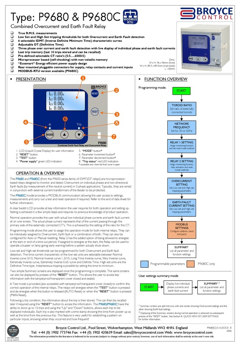
  9. Broyce Control P9680 User manual

Broyce Control P9680 User manual

Broyce Control Ltd., Pool Street, Wolverhampton, West Midlands WV2 4HN. ngland
Tel: +44 (0) 1902 773746 Fax: +44 (0) 1902 420639 mail: [email protected] Web: www.broycecontrol.com
The information provided in this literature is believed to be accurate (subject to change without prior notice); however, use of such information shall be entirely at the user’s own risk
.
P9680-3-A
1
11
1
012376
Type: P9680
Type: P9680Type: P9680
Type: P9680
Combined Overcurrent and Earth Fault Relay
Combined Overcurrent and Earth Fault RelayCombined Overcurrent and Earth Fault Relay
Combined Overcurrent and Earth Fault Relay

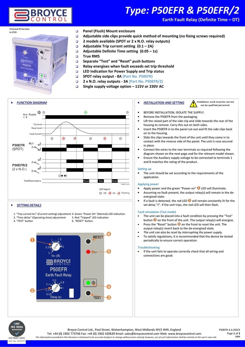
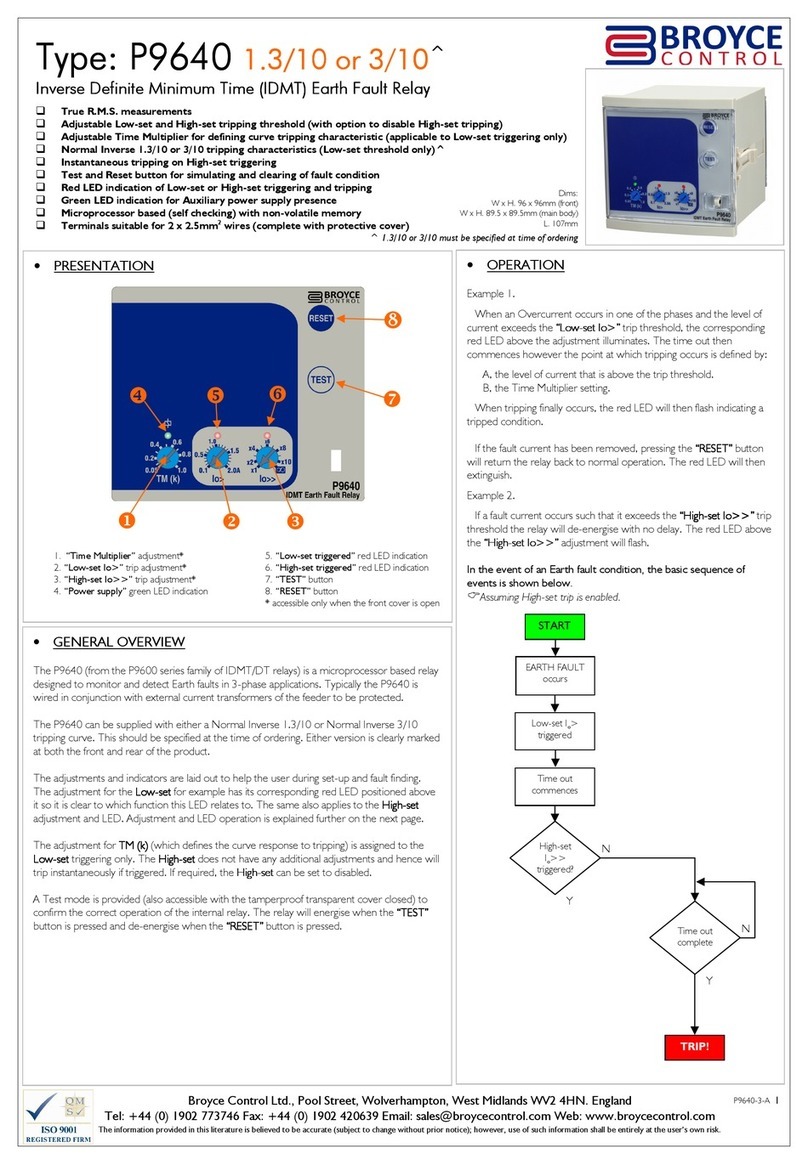
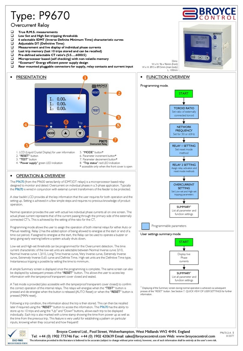
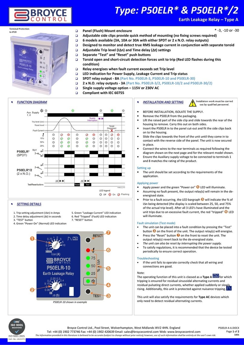
True R.M.S. measurements

Low Set and High Set tripping thresholds for both Overcurrent and Earth Fault detection

selectable IDMT (Inverse Definite Minimum Time) characteristic curves

Adjustable DT (Definitive Time)

Three phase over current and earth fault detection with live display of individual phase and earth fault currents

Last trip memory (last 10 trips stored and can be recalled)

Pre-defined selectable CT ratio’s (5:5…. 000:5)

Microprocessor based (self checking) with non-volatile memory

“Ecosmart” Energy efficient power supply design

Rear mounted pluggable connectors for supply, relay contacts and current inputs
•OP RATION & OV RVI W
The P9680
P9680 P9680
P9680 (from the P9600 series family of IDMT/DT relays) is a mi ropro essor based relay
designed to monitor and dete t Over urrent on individual phases and non-dire tional Earth faults (by
measurement of the neutral urrent) in 3-phase appli ations. Typi ally the
P9680
P9680 P9680
P9680 is wired in
onjun tion with external urrent transformers of the feeder to be prote ted.
A lear ba klit LCD provides all key information the user requires for both operation and setting up.
Setting is a hieved in a few simple steps and requires no previous knowledge of produ t operation.
Normal operation provides the user with a tual live individual phase urrents and earth fault urrent
all on one s reen. The a tual phase urrent represents that of the urrent passing through the
primary side of the externally onne ted CT’s. This is a hieved by the setting of the ratio for the CT.
Programming mode allows the user to assign the operation mode for both internal relays. They an
be individually assigned to Over urrent, Earth fault or a ombination of both. They an also be
onfigured for Auto or Manual resetting. Relay 2 has the added option of being allowed to energise
at the start or end of a time out period. If assigned to energise at the start, the Relay an be used to
operate a buzzer or lamp giving early warning before a system a tually shuts down.
Low-set and High-set thresholds an be programmed for both Over urrent and Earth fault
dete tion. The time urrent hara teristi of the low-set units are sele table between Normal
Inverse urve 3/10, Normal Inverse urve 1.3/10, Long Time Inverse urve, Very Inverse urve,
Extremely Inverse urve, Extremely Inverse 0.65 urve and Definite Time. High-set units are the
Definitive Time type. Instantaneous tripping is possible by setting the time to minimum.
Two simple Summary s reens are displayed on e the programming is omplete. The same s reens
an also be displayed by presses of the “R S T” button. This allows the user to a ess key
information with the tamperproof transparent over losed and sealed.
A Test mode is provided (also a essible with tamperproof transparent over losed) to onfirm the
orre t operation of the internal relays. The relays will energise when the “T ST” button is pressed
and de-energise when the button is released (AUTO Reset) or when the “R S T” button is pressed
(MAN Reset).
Following a trip ondition, the information about the trip is then stored. This an then be re alled
later if required using the “R S T” button to a ess the information. The P9680
P9680P9680
P9680 has the ability to
store up to 10 trips and using the “Up” and “Down” buttons, allows ea h trip to be displayed
individually. Ea h trip is also marked with a time stamp showing the time from power up as well as
the time from the previous trip. This feature is very useful for establishing a pattern on parti ular
inputs, knowing when they o urred and how frequent!
•FUNCTION OV RVI W
Programming mode.
Programmable parameters
User settings summary mode
1
Summary s reens are split into two with one s reen showing Over urrent settings and the
other showing Earth fault settings.
2
Displaying of the Summary s reens during normal operation is a hieved via subsequent
presses of the “RESET” button. See Se tion 8. QUICK VIEW OF USER SETTINGS
for further information.
•PR S NTATION
1. LCD (Liquid Crystal Display) for user information 5. “MOD ” button*
2. “R S T” button 6. Parameter in rement button*
3. “T ST” button 7. Parameter de rement button*
4. “Power supply” green LED indi ation 8. “Trip status” red LED indi ation
* a essible only when the front over is open







START
TOROID RAT
IO
Set ratio of externally
onne ted toroids
N TWORK
FR QU NCY
Set for 50 or 60Hz
onne ted toroids
R LAY 1 S TTING
Assign monitoring fun tion
and set reset mode method
R LAY 2 S TTING
Assign monitoring fun tion,
relay a tivation and reset
mode methods
OV RCURR NT
S TTING
Set Low-set and High-set
tripping parameters
ARTH FAULT
CURR NT S TTING
Set Low-set and High-set
tripping parameters
SUMMARY
1
List all parameter and
fun tion settings
START
Display live individual
phase urrents and
earth fault urrent
SUMMARY
1 2
List all parameter and
fun tion settings
Di
ms:
W x H. 96 x 96mm (front)
W x H. 89.5 x 89.5mm (main body)
L. 100mm
I
L1
0.00
A
I
L2
0.00
A
I
L3
0.00
A
I
O
0.00
A

Broyce Control Ltd., Pool Street, Wolverhampton, West Midlands WV2 4HN. ngland
Tel: +44 (0) 1902 773746 Fax: +44 (0) 1902 420639 mail: [email protected] Web: www.broycecontrol.com
The information provided in this literature is believed to be accurate (subject to change without prior notice); however, use of such information shall be entirely at the user’s own risk
.
P9680-3-A
2
22
2
012376
•PROGRAMMING
Programming/setting of the
P9680
P9680P9680
P9680
is arried out using the 3 buttons lo ated
behind the transparent over.
The button sele ts the required parameter to be hanged. The
buttons either in rement or de rement a value a ordingly.
Any adjustments made are stored by the pressing and holding of the button
until the LCD shows the word “Saved!
Saved!Saved!
Saved!” See Se tion 7. SAVING OF SETTINGS.

Please read the “Notes during programming” before commencing with the
following.
1A. TOROID RATIO

Setting the Toroid Ratio will allow the “actual” Phase currents (IL1, IL , IL3) and
Neutral current (Io) displayed on the LCD to represent that of the currents flowing
through the external CT’s. If no CT’s are used, the parameter should be set to 5/5
(i.e. 1:1). The setting applies to all CT’s.

Default setting is “5/5”
•Press and hold the button. The LCD displays a s reen showing the
hara ters “User Settings
User SettingsUser Settings
User Settings” then the following s reen appears…
•Press either or to set the primary value of the external CT’s.

The digit after the forward slash “/” cannot be changed.
1B. N TWORK FR QU NCY

Default setting is “50Hz”
•Whilst in the same s reen as that for the Toroid Ratio (see 1A.), press
the button to display the options for NETWORK FREQUENCY
NETWORK FREQUENCYNETWORK FREQUENCY
NETWORK FREQUENCY.
•Press either or to sele t between 50Hz or 60Hz. This should be
set to suit the frequen y of the network being monitored.
•Press and hold the button to set the options for “Relay 1”
“Relay 1” “Relay 1”
“Relay 1” as des ribed
in the next se tion.
2. R LAY 1 S TTING

Default setting for Relay 1 is linked to “O/C & E/F”. Resetting mode is Manual.
•The LCD displays the following s reen. The options under “1:” are displayed
and the default setting highlighted.
•Press either or to sele t how Relay 1 is assigned to tripping.
•Press the button and the options under “2:
2:2:
2:” for resetting are displayed
and the default setting highlighted.
A tual LCD presentation when adjustable parameters are displayed.
•Press either or to sele t between AUTO
AUTOAUTO
AUTO resetting or MAN
MANMAN
MANUAL
resetting (after a fault has o urred).
continued on next page…
•INSTALLATION
•B FOR INSTALLATION, ISOLAT TH SUPPLY. THIS PRODUCT IS
D SIGN D TO CONN CT TO S V RAL TYP S OF CIRCUITS.
NSUR ALL AR ISOLAT D^
•Remove the
P9680
P9680 P9680
P9680
from the pa kaging.
•Lift the raised part of the side lip in order to withdraw from the housing.
Carry this out on ea h side.
•Insert the
P9680
P9680P9680
P9680
into the panel ut-out and fit the side lips ba k on to the
housing.
•Slide the lips towards the front of the unit until they ome in to onta t with
the reverse of the panel. The unit is now se ured in pla e.
•Wire the supplied female pluggable onne tors as required.
•Plug the onne tors into the relevant so kets on the rear of the unit.
•The
P9680
P9680P9680
P9680
is now ready for powering and programming.

The front window of the P9680 is supplied with a clear protective film which can be
removed as and when necessary.
^ When arrying out future maintenan e on the produ t or appli ation and it
be omes ne essary to dis onne t the onne tors from the produ t, ensure for
the Current Transformer onne tor, they do not remain open ir uit
they do not remain open ir uitthey do not remain open ir uit
they do not remain open ir uit. This an
lead to high voltages being present on this onne tor.
•NORMAL OP RATION
•Apply power to the unit and the green “Power supply” LED will illuminate.
•The LCD will momentarily display a wel ome s reen as shown…
….then after a short delay reverts to indi ating the following information:
•T ST MOD
•Press and hold the button and both relays will energise. The LCD will
display the hara ters “T ST” and the produ t part number (as below). The
LCD ba klight and red “Trip” LED will flash.
•Release the button and the relay(s) will remain energised if set to Manual
reset or de-energise if set to Auto reset.
•Press the to de-energise relay(s) whi h are set to Manual reset. The
LCD will revert ba k to Normal operation. The LCD ba klight and red
“Trip” LED will stop flashing.

Testing should be carried out on a regular basis to check the integrity of the
P9680.
DO NOT use this product to provide a means of isolating circuits in
order to work on when placed in the “TEST”
“TEST”“TEST”
“TEST” mode. This should only be
done by means of operating isolators, circuit breakers or other
methods of removing power in this application.
I
L1
0.00
A
I
L2
0.00
A
I
L3
0.00
A
I
O
0.00
A
Installation work must be carried
out by qualified personnel.
A tual phase
urrents
A tual Earth
fault urrent
TEST
TYPE: P9680
Ver: X.X
TOROID RATIO
5 / 5
RELAY
1
CONFIG
RATION
1:
O/C
E/F
O/C & E/F
Digits whi h
an be adjusted
TYPE: P9680
Ver: X.X
Model No.
Version
TOROID RATIO
5 / 5
NETWORK FREQ ENCY
50Hz
60Hz
RELAY
1
CONFIG
RATION
1: 2:
O/C A TO
E/F MAN
O/C & E/F
Broyce Control Ltd., Pool Street, Wolverhampton, West Midlands WV2 4HN. ngland
Tel: +44 (0) 1902 773746 Fax: +44 (0) 1902 420639 mail: [email protected] Web: www.broycecontrol.com
The information provided in this literature is believed to be accurate (subject to change without prior notice); however, use of such information shall be entirely at the user’s own risk
.
P9680-3-A
3
33
3
012376
6. OV RCURR NT & ARTH FAULT SUMMARY

It is not possible to edit settings when these screens are displayed.
•Following the setting of “Earth Fault”, the LCD displays the “Over urrent
Summary” s reen showing a summary of the settings made during
programming. All settings are displayed. The sele ted CT ratio, Network
Frequen y and Relay operation (following a Reset) information is also
displayed.
•Press and hold the button to display the
“Earth Fault Summary” s reen.
7. SAVING OF S TTINGS
•If after viewing the Summary s reens the settings are orre t, press and hold
the button until the word “Saved.”
“Saved.”“Saved.”
“Saved.” appears. Any new settings are now
stored.
•The s reen will revert ba k to Normal operation.
8. QUICK VI W OF US R S TTINGS

It is not possible to edit settings when these screens are displayed.

This feature can also be activated with the front window closed!
•Press and hold the button to display the initial power up s reen.
•Press the same button again to display the “Last Tripped Information” s reen
(refer to the next page for further information on this feature).
•Press again to display the “Over urrent Summary” s reen.
•Press again to display the “Earth Fault Summary” s reen.
•Press again to display the onta t details for Broy e Control.
•Press again to revert ba k to Normal operation.
9. LAST TRIPP D INFORMATION

Refer to next page for detailed information of this feature
Notes during programming

If during programming it is necessary to abort, press the button briefly.

Pressing and holding either or for >1sec. will increment or decrement
the new value at a quicker rate.

Stepping through each User Setting screen is performed by pressing and holding
the button until the desired screen is displayed.
Short presses of the button will allow further editable settings to be changed
within a specific screen.

If the user remains in a setting or summary screen where no adjustments or button
presses are made within a certain period, the screen will revert back to Normal
operation. Additionally, any settings that have been made but not stored will not be
saved.

”O/C” refers to Overcurrent and “E/F” refers to Earth fault.
•PROGRAMMING (continued)
•Press and hold the button to set the options for “Relay 2”
Relay 2” Relay 2”
Relay 2” as des ribed
in the next se tion.
3. R LAY 2 S TTING

Default setting for Relay is linked to “O/C & E/F” and energising at the end of the
time out period. Resetting mode is Auto.
•Setting of “Relay 2” is arried out in a similar manner as “Relay 1”, however it
is ne essary to assign the relay to either energise at the start (S) or end (E) of
the time out period.
A tual LCD presentation when adjustable parameters are displayed.
•Press and hold the button to set the options for “OVERCURRENT”
“OVERCURRENT” “OVERCURRENT”
“OVERCURRENT” as
des ribed in the next se tion.
4. OV RCURR NT S TTING

The description for the Curves is abbreviated when displayed on the screen. Refer
to “IDMT Characteristic Curves” for further explanation.

Default settings for Overcurrent are shown in the last LCD screen example in this
section.
•Settings for Over urrent are displayed in turn following subsequent presses of
the button. The Low-set trip urrent (I>) is displayed first.
•Press either or to hange the urrent.
•Press the button to sele t the remaining settings and use the and
buttons to hange them.
A tual LCD presentation when adjustable parameters are displayed.
S reen example above also shows the default settings for OVERCURRENT.
•Press and hold the button to set the options for “EARTH FAULT”
“EARTH FAULT” “EARTH FAULT”
“EARTH FAULT” as
des ribed in the next se tion.

If the Curve in selection “ :” is set to Definite Time, then selection “3:” will display
“3: t>” and the required delay can then be set.

If High-set is set to Disable in selection “4:”, then I>> or t>> cannot be
adjusted.
5. ARTH FAULT S TTING

Default settings for Earth Fault are shown in the LCD screen example in this
section.
•Settings for Earth Fault are arried out in the same manner as des ribed for
Over urrent.
S reen example showing the default settings for EARTH FAULT.
•Press and hold the button to see a summary of the “OVERCURRENT”
“OVERCURRENT”“OVERCURRENT”
“OVERCURRENT”
then “EARTH FAULT”
“EARTH FAULT”“EARTH FAULT”
“EARTH FAULT” settings as des ribed in the next se tion.

If the Curve in selection “ :” is set to Definite Time, then selection “3:” will display
“3: to>” and the required delay can then be set.

If High-set is set to Disable in selection “4:”, then Io>> or to>> cannot be
adjusted.
O/C SETTING
Low set
1: I> 5.00A
O/C
S MMARY
I> 5.00A
NI 3/10
k> 0.1
I>>50.00A
t>>0.05s
R1 = MAN R2 = A TO (E)
CT=5:5, FREQ=50Hz
E/F
S MMARY
Io> 2.00A
NI 3/10
ko> 0.1
Io>>10.00A
to>>0.05s
R1 = MAN R2 = A TO (E)
CT=5:5, FREQ=50Hz
RELAY
2
CONFIG
RATION
1: 2:
O/C A TO (E)
E/F MAN (E)
O/C & E/F A TO (S)
MAN (S)
O/C SETTING
Low Set:
1: I> 5.00A
2: Curve NI 3/10
3: k> 0.1
High Set:
4: I>> 50.00A
5: t>> 0.05s
E/F
SETTING
Low Set:
1: Io> 2.00A
2: Curve NI 3/10
3: k> 0.1
High Set:
4: Io>> 10.00A
5: t
o
>> 0.05s
The letter in bra kets refers to
whether Relay 2 has been set
to trigger at the start or end of
the time out period.
(E) = E
EE
End of time out
(S) = S
SS
Start of time out
Either abbreviation an appear
after the word MAN or AUTO
See Section 3. RELAY
SETTING
Broyce Control Ltd., Pool Street, Wolverhampton, West Midlands WV2 4HN. ngland
Tel: +44 (0) 1902 773746 Fax: +44 (0) 1902 420639 mail: [email protected] Web: www.broycecontrol.com
The information provided in this literature is believed to be accurate (subject to change without prior notice); however, use of such information shall be entirely at the user’s own risk
.
P9680-3-A
4
44
4
012376
•PROGRAMMING (continued)
9A. LAST TRIPP D INFORMATION

This information is held in memory even if power is removed.
This feature allows the user to view and re all the key information relating to the last trip event and it an store up to 10 trip events. It is a essed as des ribed in Se tion 8
on the previous page.
The information displayed highlights the ause of the trip (i.e. whi h phase for example), the level of urrent at the time the trip o urred; the triggering method (Low-set
or High-set) and whi h relays were a tivated. It also shows the elapsed time from powering the
P9680
P9680P9680
P9680
to the trip o urring and displayed against “Ttrip” as well as showing
the time differen e between the trip displayed and the one previous to that. This is shown against “Tdiff”.
An example of the s reen layout is shown below.

If there is only one
trip
event
stored in the memory, the display will show
“Tdiff:
----
d
--
h
--
m
--
s” when viewed
.
Phase whi h
aused the trip
to o ur
(i.e. L2)
Level of urrent
on other inputs
at time of trip
Trip number
(1…10)
Relays that were
a tivated at trip
IL1
20.70A
I>>
1
…
IL2 89.00A R1 R2
IL3 27.50A
Io 0.00A
Ttrip: 0000d00h00m00s
Tdiff: 0000d00h00m00s
Level whi h was
triggered (i.e. High-set)
9B. R CALLING TH LAST TRIPP D INFORMATION

If the unit has logged the maximum number of trips which can be stored, then the display will show “Tdiff: ----d--h--m--s” when trip screen 10 is viewed.

The screen will revert back to Normal operation after 1 minute if no further button presses are made.

If a trip condition occurs whilst in this mode, the screen will automatically change to display the information relating to the current status.
•As des ribed in Se tion 8, use the to gain a ess to the Last Tripped Information s reen. The display will show the most re ent trip information as follows:
•If more than one trip event is stored, use the and buttons to sele t the s reens a ordingly.
•Press the button to exit the s reen information when finished or allow to time out automati ally.
IL1
1.65
A
I>
1
…
IL2 15.00A R1 R2
IL3 8.40A
Io 0.00A
Ttrip: 0001d13h15m04s
Tdiff: - - - -d - -h - -m - -s
IL1
1.65
A
I>
1
…
IL2 15.00A R1 R2
IL3 8.40A
Io 0.00A
Ttrip: 0001d19h24m56s
Tdiff: 0000d06h09m52s
IL1
1.8
0A
I>
2
…
IL2 21.35A R1 R2
IL3 9.20A
Io 0.00A
Ttrip: 0001d13h15m04s
Tdiff: - - - -d - -h - -m - -s
Ttrip:
The elapsed time from
applying power to the
urrent trip
Tdiff:
The time differen e
between the urrent trip
and the previous trip
The example on the left shows the problem on phase L2 on
both trip events. The differen e between the first re orded
trip and se ond was 6h 09m
6h 09m6h 09m
6h 09m and 52s
52s52s
52s.
9
C
.
CL ARING TH
LAST TRIPP D INFORMATION
HISTORY

Once the information has been deleted, it will not be possible to recall this.

“Ttrip” information is still retained but won’t be displayed after the carrying out this
operation (See 9D)
•Press the button to a ess the relevant s reen.
•Press the and buttons simultaneously to delete the information.
When this is omplete, the s reen will show:
•Press the button again to exit.
No previous trip info
9
D
.
CL
ARING “Ttrip” INFORMATION

If the tripping history hasn’t been deleted, previous information will be displayed
from the last time the unit was powered up.
•The “Ttrip” information will still be held in memory after deleting the trip
history is made and also if power is removed and re-applied. However,
when power is re-applied, the internal ounter will reset and start from zero
•Only when a new trip ondition o urs will the “Ttrip” information get
updated and be displayed on the most re ent s reen.
Broyce Control Ltd., Pool Street, Wolverhampton, West Midlands WV2 4HN. ngland
Tel: +44 (0) 1902 773746 Fax: +44 (0) 1902 420639 mail: [email protected] Web: www.broycecontrol.com
The information provided in this literature is believed to be accurate (subject to change without prior notice); however, use of such information shall be entirely at the user’s own risk
.
P9680-3-A
5
55
5
012376
I
L1
20.7
0
A
I>
I
L2
40.00
A
I
L3
27.50
A
I
O
0.00
A
Phase with fault
I
L1
20.7
0
A
I>>
I
L2
89.00
A R1 R2
I
L3
27.50
A
I
O
0.00
A
I
L1
0.
0
0
A
I
L2
0.00
A
I
L3
0.00
A
Io>
I
O
1.00
A
I
L1
0.
0
0
A
I
L2
0.00
A
I
L3
0.00
A
Io>>
I
O
8.00
A
R1
Low-set
triggered
High-set
triggered
Relay(s) whi h
energised on
tripping
Low-set
triggered
High-set
triggered
Relay(s) whi h
energised on
tripping
Earth fault
urrent
OVERCURRENT
fault o urs
Low-set I>
triggered
Run IDMT or DT
delay t>
Run DT delay
t>>
High-set
I>>
triggered?
N
Y
TRIP!
Delay
t>
omplete?
N
Y
Delay
t>>
omplete?
N
Y
START
EARTH FAULT
o urs
Low-set Io>
triggered
Run IDMT or DT
delay to>
Run DT delay
to>>
High-set
Io>>
triggered?
N
Y
TRIP
!
Delay
to>
omplete?
N
Y
Delay
to>>
omplete?
N
Y
START
•TRIPPING MOD S
1. OV RCURR NT
•A fault whi h develops on a phase will be indi ated by an in rease in urrent
reading on the LCD. When the level of urrent ex eeds the Low-set setting,
the phase at fault will be highlighted by the digits flashing.
•The LCD ba klight will flash.
•Relay 2 will energise if assigned to Over urrent and set to energise at the start
of the time out period (See Se tion 3. RELAY 2 SETTING).
•The hara ters “I>” will display to indi ate the Low-set has been triggered.
•If the urrent ontinues to in rease above the High-set setting, the hara ters
“I>” will hange and display “I>>” to indi ate the High-set has been
triggered.
•When the unit finally trips, the digits of the phase at fault will stop flashing and
remain highlighted. This allows the user to see whi h phase was at fault and
aused the unit to trip.
•The red “Tripped”
“Tripped”“Tripped”
“Tripped” LED will also flash.
•The relays whi h energised are also displayed on the s reen after tripping.
•Press to reset and return the unit ba k to normal operation (assuming
the fault has been leared). The LCD reverts ba k to displaying the normal
system urrents and the red “Tripp
“Tripp“Tripp
“Tripped”
ed”ed”
ed” LED stops flashing.

If either relay is set for Auto resetting, then they would have de-energised after the
fault had cleared. The corresponding relay ident (i.e. R1 and/or R ) on the display
would also disappear. Pressing the “RESET”
“RESET” “RESET”
“RESET” button will only clear the LCD. If either
relay is set for Manual resetting, then pressing the “RESET”
“RESET”“RESET”
“RESET” button will de-energise the
relay(s) and clear the LCD.
In the event of an Overcurrent condition, the basic sequence of events is
shown below.

Assuming High-set trip is enabled.
2. ARTH FAULT
•When an Earth fault o urs ausing a flow in urrent through the Neutral, an
in rease in urrent reading on the LCD will o ur. When the level of urrent
ex eeds the Low-set setting, the reading will be highlighted by the digits
flashing.
•The LCD ba klight will flash.
•Relay 2 will energise if assigned to Earth fault and set to energise at the start of
the time out period (See Se tion 3. RELAY 2 SETTING).
•The hara ters “Io>” will display to indi ate the Low-set has been triggered.
•If the urrent ontinues to in rease above the High-set setting, the hara ters
“Io>” will hange and display “Io>>” to indi ate the High-set has been
triggered.
•When the unit finally trips, the digits will stop flashing and remain highlighted.
This allows the user to see what aused the unit to trip.
•The red “Tripped”
“Tripped”“Tripped”
“Tripped” LED will also flash.
•The relays whi h energised are also displayed on the s reen after tripping.
•Press to reset and return the unit ba k to normal operation (assuming
the fault has been leared). The LCD reverts ba k to displaying the normal
system urrents and the red “Tripped”
“Tripped”“Tripped”
“Tripped” LED stops flashing.

If either relay is set for Auto resetting, then they would have de-energised after the
fault had cleared. The corresponding relay ident (i.e. R1 and/or R ) on the display
would also disappear. Pressing the “RESET”
“RESET”“RESET”
“RESET” button will only clear the LCD. If either
relay is set for Manual resetting, then pressing the “RESET”
“RESET”“RESET”
“RESET” button will de-energise the
relay(s) and clear the LCD.
In the event of an arth fault condition, the basic sequence of events is shown
below.

Assuming High-set trip is enabled.
Broyce Control Ltd., Pool Street, Wolverhampton, West Midlands WV2 4HN. ngland
Tel: +44 (0) 1902 773746 Fax: +44 (0) 1902 420639 mail: [email protected] Web: www.broycecontrol.com
The information provided in this literature is believed to be accurate (subject to change without prior notice); however, use of such information shall be entirely at the user’s own risk
.
P9680-3-A
6
66
6
012376
1
10 20
I/I>
I/I>I/I>
I/I>
1 10 20
I/I>
I/I>I/I>
I/I>
•IDMT CHARACT RISTIC CURV S
* Abbreviations used in the LCD s reen for the sele ted IDMT hara teristi urve.
The sequen e of urves that are presented to the user when programming is shown below
k
kk
k
1.0
0.9
0.8
0.7
0.6
0.5
0.4
0.3
0.2
0.1
0.05
Normal nverse 1.3/10
Normal nverse 1.3/10 Normal nverse 1.3/10
Normal nverse 1.3/10
(N 1.3/10)*
(N 1.3/10)*(N 1.3/10)*
(N 1.3/10)*
1
10 20
I/I>
I/I>I/I>
I/I>
k
kk
k
1.0
0.9
0.8
0.7
0.6
0.5
0.4
0.3
0.2
0.1
0.05
t
t
t
t (s)
(s)
(s)
(s)
10
1
0.1
0.01
t
t
t
t
(s)
(s)
(s)
(s)
Normal nverse 3/10
Normal nverse 3/10Normal nverse 3/10
Normal nverse 3/10
(N 3/10)*
(N 3/10)*(N 3/10)*
(N 3/10)*
t
t
t
t
(s)
(s)
(s)
(s)
k
kk
k
1.0
0.9
0.8
0.7
0.6
0.5
0.4
0.3
0.2
0.1
0.05
10
1
0.1
1 10 20
I/I>
I/I>I/I>
I/I>
Long Time nverse
Long Time nverse Long Time nverse
Long Time nverse
(LT )*
(LT )*(LT )*
(LT )*
.
200
100
10
1
0.1
k
kk
k
1.0
0.9
0.8
0.7
0.6
0.5
0.4
0.3
0.2
0.1
0.05
t
t
t
t
(s)
(s)
(s)
(s)
1 10 20
I/I>
I/I>I/I>
I/I>
Very nverse
Very nverse Very nverse
Very nverse
(V )*
(V )*(V )*
(V )*
1
10 20
I/I>
I/I>I/I>
I/I>
k
kk
k
1.0
0.9
0.8
0.7
0.6
0.5
0.4
0.3
0.2
0.1
0.05
10
1
0.1
0.01
t
t
t
t
(s)
(s)
(s)
(s)
Extremely nverse
Extremely nverse Extremely nverse
Extremely nverse
(E )*
(E )*(E )*
(E )*
k
kk
k
0.9
0.8
0.7
0.6
0.5
0.4
0.3
0.2
100
10
1
0.1
0.01
t
t
t
t
(s)
(s)
(s)
(s)
0.1
0.05
1 10 20
I/I>
I/I>I/I>
I/I>
Extremely nverse
Extremely nverse Extremely nverse
Extremely nverse
(E 0.65)*
(E 0.65)*(E 0.65)*
(E 0.65)*
k
kk
k
0.9
0.8
0.7
0.6
0.5
0.4
0.3
0.2
0.1
1
10 20
I/I>
I/I>I/I>
I/I>
1000
100
10
1
0.1
0.01
1.0
0
NI 3/10
NI 1.3/10
LTI
EI
EI 0.65
VI
t
t
t
t
(s)
(s)
(s)
(s)
Broyce Control Ltd., Pool Street, Wolverhampton, West Midlands WV2 4HN. ngland
Tel: +44 (0) 1902 773746 Fax: +44 (0) 1902 420639 mail: [email protected] Web: www.broycecontrol.com
The information provided in this literature is believed to be accurate (subject to change without prior notice); however, use of such information shall be entirely at the user’s own risk
.
P9680-3-A
7
77
7
012376
Ele tri al life:
≥
150,000 ops at rated load
Diele tri voltage: 2kV AC (rms) IEC 60947-1
Rated impulse
withstand voltage: 4kV (1.2 / 50µS) IEC 60664
Max. DC Load Breaking Capa ity Ele tri al Enduran e
Housing: Flame retardant Lexan
Prote tion: IP55 / IP20 (rear)
Weight: ≈ 600g
Mounting: Panel mounting. Cut-out = 91 x 91mm (± 0.5mm)
Max. panel thi kness: 12mm
Terminal type: UL94-V0 rated pluggable and re-wireable female
onne tors omprising:
2-way (Power supply 1, 2)
6-way (Relay onta ts 3….8)
8-way (Phase urrent and neutral inputs 9….16)
Terminal ondu tor size: 0.05 - 2.5mm
2
(30 - 12AWG)
Re ommended tightening
torque: 4.4in lb (0.5Nm)
Wire stripping length: 0.24 – 0.30in (6 – 7.5mm)
Approvals: Conforms to IEC. CE and and RoHS Compliant.
EMC: Immunity: EN/IEC 61000-6-2
Emissions: EN/IEC 61000-6-4
Generi : IEC 60255-26 (EMC), IEC 255-3, IEC
60255-151
( ) Bold digits in bra kets refer to terminal numbers on the rear of the unit.
Options:
The P9600 range also in ludes individual Over urrent or Earth fault relays
available with either IDMT or DT hara teristi s. Please refer to separate data
sheets.
•T CHNICAL SP CIFICATION
Aux. Supply voltage Un (1, 2): 85 – 265VAC/85 - 370VDC
1
18 – 55VAC/18 – 72VDC*
(Voltage range should be specified at time of
ordering)
Rated frequen y: 50/60Hz (AC Supplies)
Isolation: Over voltage at. III
Rated impulse
withstand voltage:
1
4kV (1.2 / 50µS) IEC 60664
Power onsumption: 3W max.
* If onne ting a fuse externally, a Time Delay type is re ommended with a rating of 0.5A or
higher.
Rated urrent input In: 5A (dire tly onne ted)
Rated frequen y: 50/60Hz
Burden: <0.4VA @ In
Overload: 4 x In ( ontinuous)
External CT’s (9……16): Class P re ommended. (with 5A se ondary)
Maximum CT primary
urrent rating: 6000A
Over urrent settings:
Low-set trip (I>): 0.50 – 10.00A (10 – 200%)
Low-set time multiplier (k>): 0.05 – 1.00
Low-set definite time (t>): 0.05 – 100s
High-set trip (I>>): 0.5 – 100A (10 – 2000%) or disable
High-set definite time (t>>): 0.05 – 2.5s
Earth fault settings:
Low-set trip (I
o
>): 0.10 – 5.00A (2 – 100%)
Low-set time multiplier (k
o
>): 0.05 – 1.00
Low-set definite time (t
o
>): 0.05 – 100s
High-set trip (I
o
>>): 0.10 – 50.00A (2 – 1000%) or disable
High-set definite time (t
o
>>): 0.05 – 2.5s
Pi k up value: +2% of trip setting
A ura y:
Prote tion thresholds: ± 5%
Time delay (DT): ± 5% (with a minimum of 50mS)
Time delay (IDMT): ± 5% (with a minimum of 50mS and I > 1.2 x
set-trip)
A tual phase urrent: ± 1% of rated urrent In
A tual Earth fault urrent: ± 1% of rated urrent In
Display update time: <1 se .
Repeat a ura y: ± 0.5% @ onstant onditions
Ambient temperature: -10 to +60°C
Relative humidity: +95%
Output:
(RL1 - 3, 4, 5): 1 x SPDT relay
(RL2 - 6, 7, 8): 1 x SPDT relay
Output rating: AC1 250V 8A (2000VA)
AC15 250V 5A (1250VA)
DC1
25V 8A (200W)
•CONN CTION DIAGRAM
L1
L2
L3
N
A1 A2
RL1
RL2
Aux.
1 2 3 4 5 6 7
9
8
10 11 12 13 14
16
15
I
L1
I
L2
I
L3
I
N
•DIM NSIONS
96
96
MADE IN U.K.
10
100
89.5
96
Front view Side view
All dimensions are in mm.

Other Broyce Control Relay manuals

Broyce Control P9650 User manual

Broyce Control

Broyce Control P9650 User manual

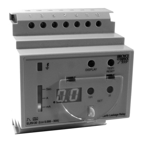
Broyce Control ELRV-30 User manual

Broyce Control

Broyce Control ELRV-30 User manual

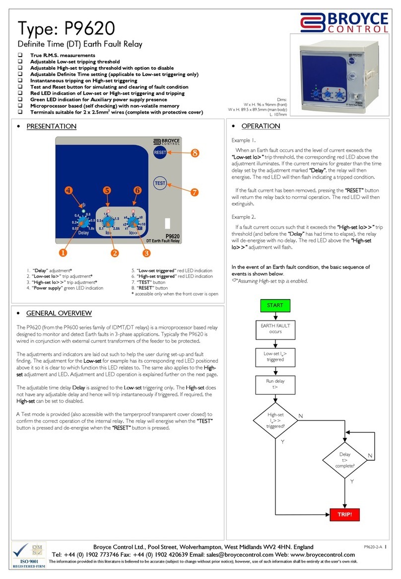
Broyce Control P9620 User manual

Broyce Control

Broyce Control P9620 User manual

Broyce Control P9640 User manual

Broyce Control

Broyce Control P9640 User manual

Broyce Control P9680C User manual

Broyce Control

Broyce Control P9680C User manual

Broyce Control EcoSmart P9670 User manual

Broyce Control

Broyce Control EcoSmart P9670 User manual

Broyce Control P9660 User manual

Broyce Control

Broyce Control P9660 User manual

Broyce Control P50EFR User manual

Broyce Control

Broyce Control P50EFR User manual

Broyce Control P9625 User manual

Broyce Control

Broyce Control P9625 User manual

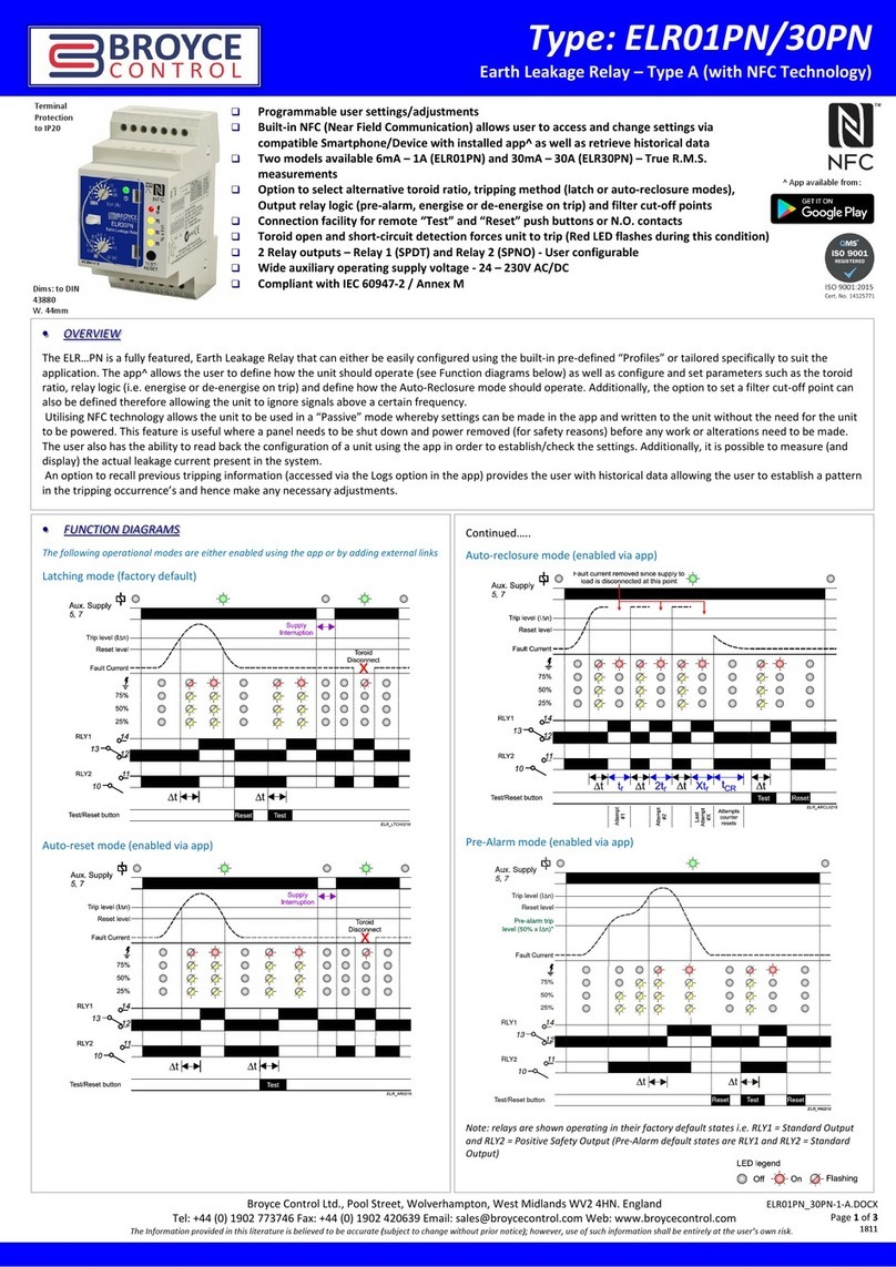
Broyce Control ELR01PN User manual

Broyce Control

Broyce Control ELR01PN User manual

Broyce Control P9600 Series User manual

Broyce Control

Broyce Control P9600 Series User manual

Broyce Control P50ELR Series User manual

Broyce Control

Broyce Control P50ELR Series User manual

Broyce Control ELRV-30 User manual

Broyce Control

Broyce Control ELRV-30 User manual

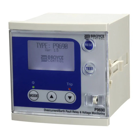
Broyce Control P9690 User manual

Broyce Control

Broyce Control P9690 User manual

Popular Relay manuals by other brands

F&F BIS-419-LED quick start guide

F&F

F&F BIS-419-LED quick start guide

Schweitzer Engineering Laboratories SEL-787 instruction manual

Schweitzer Engineering Laboratories

Schweitzer Engineering Laboratories SEL-787 instruction manual

Pilz PNOZ X3.2 operating manual

Pilz

Pilz PNOZ X3.2 operating manual

Mikro DIN310 user manual

Mikro

Mikro DIN310 user manual

Seg HighTECH MRR1 manual

Seg

Seg HighTECH MRR1 manual

ABB Relion 615 series installation manual

ABB

ABB Relion 615 series installation manual

Thytronic NA011 manual

Thytronic

Thytronic NA011 manual

GE F60 instruction manual

GE

GE F60 instruction manual

Omron K8AB-VS Series quick start guide

Omron

Omron K8AB-VS Series quick start guide

Astrel Group rialto installation manual

Astrel Group

Astrel Group rialto installation manual

SLV SLV CONTROL 470806 Quick installation guide

SLV

SLV SLV CONTROL 470806 Quick installation guide

ABB SPAM 150 C technical information

ABB

ABB SPAM 150 C technical information

NR Electric PCS-9611 instruction manual

NR Electric

NR Electric PCS-9611 instruction manual

BrickElectric BEM104 manual

BrickElectric

BrickElectric BEM104 manual

Eurotherm TE200S user manual

Eurotherm

Eurotherm TE200S user manual

DLI DIN4 user guide

DLI

DLI DIN4 user guide

Mart BR-11 user manual

Mart

Mart BR-11 user manual

GE CEY52B instructions

GE

GE CEY52B instructions

manuals.online logo
manuals.online logoBrands
  • About & Mission
  • Contact us
  • Privacy Policy
  • Terms and Conditions

Copyright 2025 Manuals.Online. All Rights Reserved.