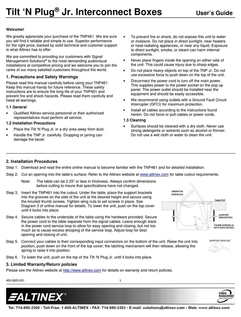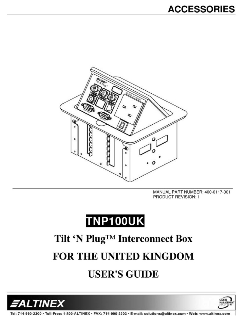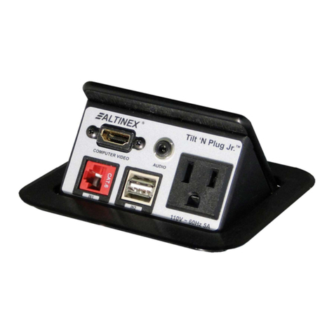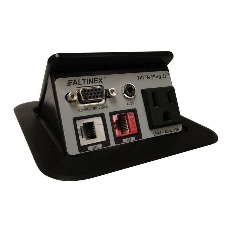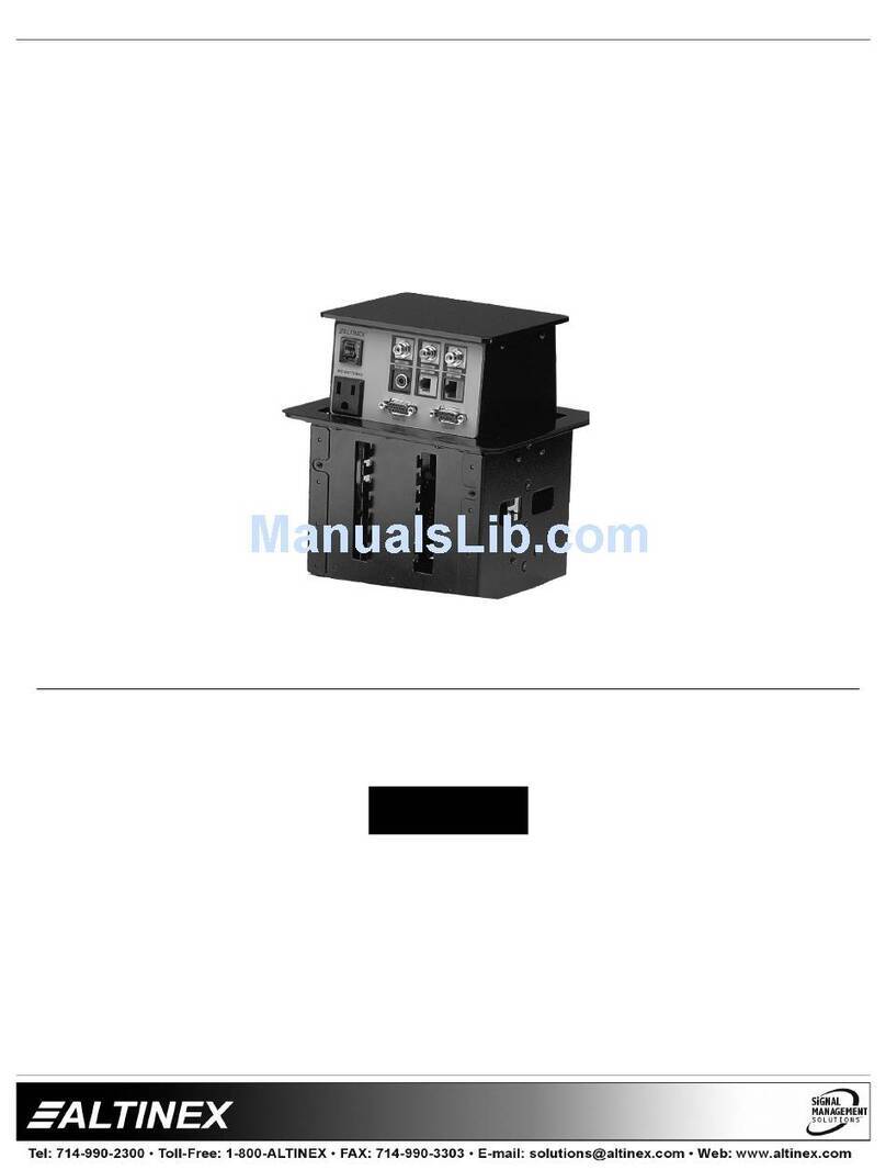
TNP600
TNP600TNP600
TNP600/
//
/ C
CC
Customizable
ustomizableustomizable
ustomizable T
T T
Tilt
iltilt
ilt ‘N P
‘N P ‘N P
‘N Plug
luglug
lug
®
®®
®
User’s Guide
400-0493-002
1
Welcome!
We greatly appre iate your pur hase of the TNP600 Customizable
TILT ‘N PLUG
®
. We are sure you will find it reliable and simple to use.
Superior performan e for the right pri e, ba ked by solid te hni al and
ustomer support is what ALTINEX has to offer.
We are ommitted to providing our ustomers with
Signal Management Solutions
®
to the most demanding audiovisual
installations at very ompetitive pri ing and we wel ome you to join the
ranks of our many satisfied ustomers throughout the world.
1. Precautions and Safety Warnings
Please read this manual arefully before using your TNP600. Keep this
manual handy for future referen e. These safety instru tions are to ensure
the long life of your TNP600 and to prevent fire and sho k hazards. Please
read them arefully and heed all warnings.
1.1 General
•Unauthorized personnel shall not open the unit, as there are
high-voltage omponents inside.
•Qualified ALTINEX servi e personnel or their authorized
representatives must perform all servi e.
1.2 Installation Precautions
•For best results, pla e the TNP600 in a dry area away from dust.
•To prevent fire or sho k, do not expose this unit to water or moisture.
Do not pla e the TNP600 in dire t sunlight, near heaters or heat
radiating applian es, or near any liquid. Exposure to dire t sunlight,
smoke, or steam an harm internal omponents.
•Handle the TNP600 arefully. Dropping or jarring an damage the
bezel.
•Never pla e fingers inside the opening on either side of the unit. This
a tion ould ause injury due to sharp edges inside.
•Do not pla e heavy obje ts on top of the TNP600. Do not use ex essive
for e to push down on the top of the unit.
•Dis onne t the TNP600’s power ord to turn off the main power. This
supplies power to the power so ket on the pop up panel. The power
outlet should be installed near the equipment and be easily a essible.
•We re ommend using wall outlets with a Ground Fault Cir uit
Interrupter (GFCI) for maximum prote tion.
•Install all ables a ording to the instru tions found herein. Do not
for e or pull out any able or power ord atta hed to the TNP600.
1.3 Cleaning
•Surfa es should be leaned with a dry loth. Never use strong
detergents or solvents su h as al ohol or thinner. Do not use a wet loth
or water to lean the unit.
1.4 FCC Notice
•This devi e omplies with Part 15 of the FCC Rules. Operation is
subje t to the following two onditions: (1) This devi e may not ause
harmful interferen e, and (2) this devi e must a ept any interferen e
re eived, in luding interferen e that may ause undesired operation.
•This equipment has been tested and found to omply with the limits for
a Class A digital devi e, pursuant to Part 15 of the FCC Rules. These
limits are designed to provide reasonable prote tion against harmful
interferen e when the equipment is operated in a ommer ial
environment. This equipment generates, uses, and an radiate radio
frequen y energy and, if not installed and used in a ordan e with the
instru tions found herein, may ause harmful interferen e to radio
ommuni ations. Operation of this equipment in a residential area is
likely to ause harmful interferen e in whi h ase the user will be
required to orre t the interferen e at his expense.
•Any hanges or modifi ations to the unit not expressly approved by
ALTINEX, In . ould void the user’s authority to operate the
equipment.
2. Installation Procedures
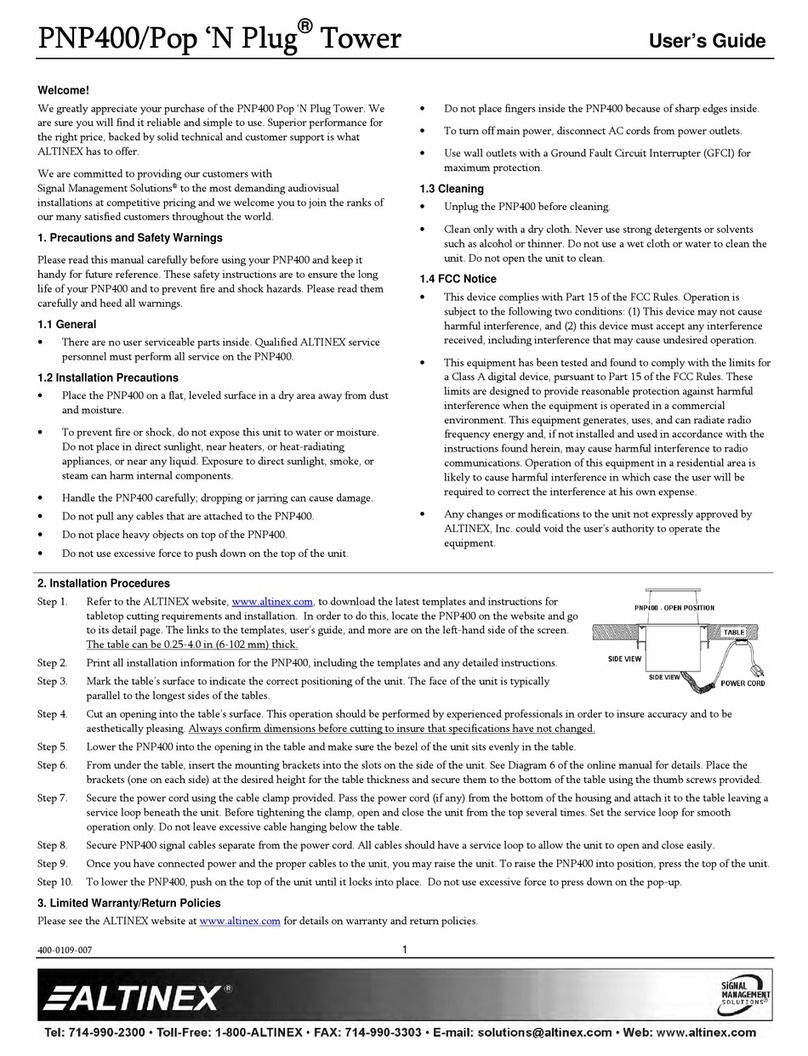
Step 1. Cut an opening into the table’s surfa e. Refer to the ALTINEX website at www.altinex. om for table utout requirements.
Note: The table an be 2.50” or less in thi kness. Always onfirm dimensions before utting to insure that spe ifi ations have not hanged.
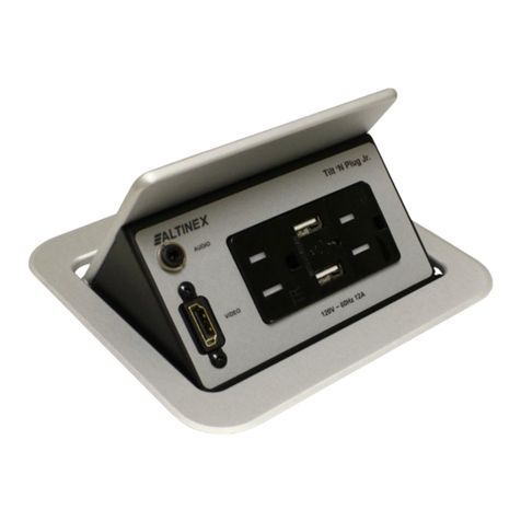
Step 2. Insert the TNP600 into the table utout.
Step 3. Pla e the support bra kets under the table and pla e them between the support mount grooves on the side of the TNP600. Atta h the bra kets to the
groove at the desired height and se ure them to the bottom of the table using the thumbs rews provided.
Step 4. To lower the unit, push on the top of the TNP600 until it lo ks into pla e.
Note: A standard, empty, TNP600 does not lat h in the down position. A able support bra ket is required. The exa t able support bra ket required
is determined at the time of ustomization.
If Custom Plates Are Installed
Step 5. Se ure all ables to the underside of the table using the able lamps and s rews in luded with the TNP600. Pass the power ord from the bottom of
the housing and atta h it to the table separate from the signal ables.
Leave enough sla k in the servi e loop to allow for easy opening and losing, but not too mu h as to ause ex ess drooping of the servi e loop.
Step 6. Conne t the appropriate ables with the orre t input onne tors on the bottom of the unit.
Step 7. On e you have applied power and onne ted the proper ables on the bottom of the unit you may raise the unit. To raise the TNP600 into position,
push down on the front of the top over; the lat hing me hanism will then release, allowing the pneumati spring to raise it into position.
Note: It may be ne essary to adjust the servi e loop of the ables for optimal performan e.
3. Limited Warranty/Return policies
Please see the ALTINEX website at www.altinex. om for details on warranty and return poli ies.
