manuals.online logo
Brands
  1. Home
  2. •
  3. Brands
  4. •
  5. Lutron Electronics
  6. •
  7. Control System
  8. •
  9. Lutron Electronics Architrave GRAFIK5000 User manual

Lutron Electronics Architrave GRAFIK5000 User manual

1 2 3 4
1 2 3 4 5 6
Architrave™Style Controls
OMX-4SLB-DW 4 Button Control
(Class 2/PELV Device)
Description
The OMX-4SLB-DW Architrave™Style Control provides local
access to the Lighting Control System to:
■Select groups of scenes in the Lighting Control System.
■Temporarily change the light settings for the current scene.
■Turn lighting zones off/on.
■Activate other system functions. Refer to the GRAFIK
5000/GRAFIK 6000 Setup Software User's Guide for other
assignable functions.
Important Notes
1. READ ALL INSTRUCTIONS CAREFULLY BEFORE STARTING
INSTALLATION.
2. This control must be installed by a qualified electrician.
3. Install in accordance with the National Electric Code and all
applicable local regulations.
4. Turn power OFF at the control panel before installing
controls. Do not connect high-voltage power to low-voltage
terminals. Improper wiring can result in personal injury and
damage to the control or to other equipment.
5. Use only a cloth with warm water and mild soap to clean
faceplates (no chemical cleaners).
Installation
1. Prewiring: The Control Links require special wiring
considerations. Refer to the GRAFIK 5000/GRAFIK 6000
Installation Guide and Lutron job drawings for wiring restrictions
and limitations that apply to your specific project.
2. Turn power OFF.
WARNING: Always turn off the power to the control
panel before doing any work. Failure to do so can
result in damage to equipment.
3. Assign Addresses:
Address all controls on the Control Link. Refer to Lutron job
drawings for any preassigned, job-specific address for each
control. Each Control Link can support up to 32 controls. For
proper system operation, each control on a link must have a
unique address. Refer to Rear View of Control. Set DIP Switches
1-5 on the back of each control to one of the positions illustrated
in Table 1. Record assignments in the "Location" column for future
reference.
4. Strip insulation from wires so 3/8" (10 mm) bare wire is exposed.
The terminals will accept up to two #18 AWG (1.0 mm2) wires. If
wires are larger, splice a #18 AWG (1.0 mm2) wire to the wires to
make the connection.
5. Connect wiring as shown in Typical Control Link Wiring Diagram
on the next page. Confirm all connections.
6. Mount Control as shown in the Mounting Diagram. Mounting
shown with optional Lutron backbox (Part No. 241-663) or with-
out. Wood screws are also provided for mounting control without a
backbox. Please note: The yoke must be flush with the surface of
the wall so that the faceplate will mount properly. In addition, the
screws must be driven into a material that can support them.
Lutron recommends framing the location in wood.
7. Restore power to the control panel after the installation of the
system is complete.
Indicator LEDs Scene Select
Buttons
Raise/Lower
OMX-4SLB 4 Button Control
DIP Switches:
switches 1-5
set Address
(6 is unused)
Class 2/PELV
Terminal:
Control Link wiring
to Lighting Control
Panel.
Mounting Diagram
(without backbox) Rear View of Control
Installation Instructions
Please Leave for Occupant
Wall Stud
Wood
Screws
Yoke
Yoke
/
®
™
Optional Lutron
Wallbox P/N 241-663
Mounting Diagram (with backbox)
3/8 in. (10 mm)
1
2
3
4
5
6
7
8
9
10
11
12
13
14
15
16
17
18
19
20
21
22
23
24
25
26
27
28
29
30
31
32
1 2 3 4 5 6 1 2 3 4 5 6 1 2 3 4 5 6 1 2 3 4 5 6
1 2 3 4
1 2 3 4 5 6
123456
4
3
2
1
1 2 3 4 5 6
1: WHITE/BLACK
2: RED
3: YELLOW
4: BLUE
1
2
3
4
43
1 Common
2+V
3MUX
4MUX
5 Shield
34
SHIELD
Control
Link
Power
Cable Data
Cable
Wiring Notes:
1. Connection of the control to the Control Link should be made inside the control's wallbox or in a junction box (provided by others)
located no more than 8 ft. (2.4 m) from control.
2. Control Link wiring MUST NOT be run in the same raceway as 120VAC or 277VAC.
3. Total Control Link length is not to exceed 2000 ft. (610 m) unless signal is boosted using a link booster (MX-RPTR).
4. Data cable shield must be maintained throughout the Control Link. DO NOT connect the shield to earth ground.
5. Refer to the GRAFIK 5000/GRAFIK 6000 Installation Guide and Lutron job drawings for power cable and data cable (Control Link)
wiring restrictions and limitations.
6. Control Link requires a LT-1, Link Termination Assembly, at each end of the Control Link. Refer to the LT-1 instruction sheet for
location and installation information.
Address Switch Location
# Setting Address Switch Location
# Setting
Switch
Down (OFF)
Switch Up
(ON)
Typical Control Link Wiring Diagram
Table 1: Address Selection
Control Panel Last Control on
Control Link
(32 maximum)
Typical Control Typical Control
LT-1 (Note 6)LT-1 (Note 6)
Note 1 & 4Note 1 & 4 Note 1 & 4
Control
Link
Terminals
Lutron Electronics Co., Inc.
Made and printed in U.S.A.
P/N 030-623 Rev. B 5/01
LIMITED WARRANTY
Lutron will, at its option, repair or replace any unit that is defective in materials or manufacture
within one year after purchase. For warranty service, return unit to place of purchase or mail to
Lutron at 7200 Suter Rd., Coopersburg, PA 18036-1299, postage pre-paid.
This warranty is in lieu of all other express warranties, and the implied warranty of
merchantability is limited to one year from purchase. This warranty does not cover
the cost of installation, removal or reinstallation, or damage resulting from misuse,
abuse, or improper or incorrect repair, or damage from improper wiring or
installation. This warranty does not cover incidental or consequential damages.
Lutron’s liability on any claim for damages arising out of or in connection with the
manufacture, sale, installation, delivery, or use of the unit shall never exceed the
purchase price of the unit.
This warranty gives you specific legal rights, and you may also have other rights which vary from
state to state. Some states do not allow limitations on how long an implied warranty lasts, so the
above limitation may not apply to you. Some states do not allow the exclusion or limitation of
incidental or consequential damages, so the above limitation or exclusion may not apply to you.
Grafik 5000 and Architrave are trademarks; Lutron and Grafik 6000 are registered trademarks of
Lutron Electronics Co., Inc.
© 2001 Lutron Electronics Co., Inc.
Internet: www.lutron.com
E-mail: product@lutron.com
WORLD HEADQUARTERS
Lutron Electronics Co. Inc.,
TOLL FREE: (800) 523-9466
(U.S.A., Canada, Caribbean)
Tel: (610) 282-3800;
International ++1- 610-282-3800
Fax: (610) 282-1243;
International ++1-610-282-1243
GREAT BRITAIN
Lutron EA Ltd.,
Tel: (171) 702-0657;
International ++44-(0)207-702-0657
Fax: (171) 480-6899;
International ++44-(0)207-480-6899
GERMANY
Lutron Electronics GmbH
Tel: (309) 710-4590;
International ++49-30-97-10-4590
Fax: (309) 710-4591;
International ++49-30-97-10-4591
FRANCE
Lutron LTC
International ++33-(0)1-44-70-71-86
Int’l Fax: ++33-(0)1-44-70-70-97
ASIAN HEADQUARTERS
Lutron Asuka Corporation (Japan)
Tel: (03) 5405-7333;
International ++81-3-5405-7333
Fax: (03) 5405-7496;
International ++81-3-5405-7496
HONG KONG SALES OFFICE
Lutron GL (Hong Kong)
Tel: 2104-7733;
International ++852-2104-7733
Fax: 2104-7633;
International ++852-2104-7633
SINGAPORE
Lutron GL (Singapore)
Tel: ++65-220-4666
Fax: ++65-220-4333
This manual suits for next models

2

Other Lutron Electronics Control System manuals

Lutron Electronics RadioRA 2 User manual

Lutron Electronics

Lutron Electronics RadioRA 2 User manual

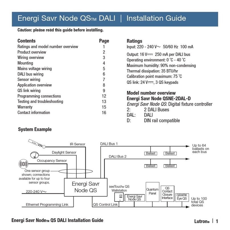
Lutron Electronics Energi Savr Node QS DALI User manual

Lutron Electronics

Lutron Electronics Energi Savr Node QS DALI User manual

Lutron Electronics Grafik Eye User manual

Lutron Electronics

Lutron Electronics Grafik Eye User manual

Lutron Electronics VISEO GRAFIK5000 User manual

Lutron Electronics

Lutron Electronics VISEO GRAFIK5000 User manual

Lutron Electronics AuroRa User manual

Lutron Electronics

Lutron Electronics AuroRa User manual

Lutron Electronics RadioRA 2 User manual

Lutron Electronics

Lutron Electronics RadioRA 2 User manual

Lutron Electronics Pico PJL-2B User manual

Lutron Electronics

Lutron Electronics Pico PJL-2B User manual

Lutron Electronics PJ2-3BRL User manual

Lutron Electronics

Lutron Electronics PJ2-3BRL User manual

Lutron Electronics RadioRA User manual

Lutron Electronics

Lutron Electronics RadioRA User manual

Lutron Electronics RadioRA-SR User manual

Lutron Electronics

Lutron Electronics RadioRA-SR User manual

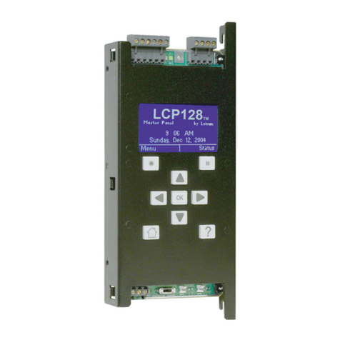
Lutron Electronics LCP128 User manual

Lutron Electronics

Lutron Electronics LCP128 User manual

Lutron Electronics RadioRA 2 User manual

Lutron Electronics

Lutron Electronics RadioRA 2 User manual

Lutron Electronics RadioRA Assembly instructions

Lutron Electronics

Lutron Electronics RadioRA Assembly instructions

Lutron Electronics myRoom User manual

Lutron Electronics

Lutron Electronics myRoom User manual

Lutron Electronics homeworks qs User manual

Lutron Electronics

Lutron Electronics homeworks qs User manual

Lutron Electronics Grafik Eye GRX-CCO-8 User manual

Lutron Electronics

Lutron Electronics Grafik Eye GRX-CCO-8 User manual

Lutron Electronics GRAFIK Eye QSG-3PCE Operating instructions

Lutron Electronics

Lutron Electronics GRAFIK Eye QSG-3PCE Operating instructions

Lutron Electronics Stanza User manual

Lutron Electronics

Lutron Electronics Stanza User manual

Lutron Electronics GRAFIK 6000 User manual

Lutron Electronics

Lutron Electronics GRAFIK 6000 User manual

Lutron Electronics RRD-6CL-WH User manual

Lutron Electronics

Lutron Electronics RRD-6CL-WH User manual

Popular Control System manuals by other brands

FUTABA GYA460 instruction manual

FUTABA

FUTABA GYA460 instruction manual

Ingrasys iPoMan II-1200 Quick installation guide

Ingrasys

Ingrasys iPoMan II-1200 Quick installation guide

Norac UC4.5 installation manual

Norac

Norac UC4.5 installation manual

Fireye M-SERIES II manual

Fireye

Fireye M-SERIES II manual

Seav Pro AUT-400 instruction manual

Seav

Seav Pro AUT-400 instruction manual

FRC EGP operating instructions

FRC

FRC EGP operating instructions

Tactic TTX240 instruction manual

Tactic

Tactic TTX240 instruction manual

Leb Electronics CTR310 instructions

Leb Electronics

Leb Electronics CTR310 instructions

fortessa 3800-F Hardware manual

fortessa

fortessa 3800-F Hardware manual

Eaton Crouse-Hinds GHG 61 R Series operating instructions

Eaton

Eaton Crouse-Hinds GHG 61 R Series operating instructions

Stahl 8220 Series operating instructions

Stahl

Stahl 8220 Series operating instructions

Intelligas EGIP installation guide

Intelligas

Intelligas EGIP installation guide

U.S. Security Solutions CA601 user manual

U.S. Security Solutions

U.S. Security Solutions CA601 user manual

Cisco SCH-CONTROL-200 reference guide

Cisco

Cisco SCH-CONTROL-200 reference guide

iLumTech BlueBridge user guide

iLumTech

iLumTech BlueBridge user guide

Mitsubishi SC-SL4-AE installation manual

Mitsubishi

Mitsubishi SC-SL4-AE installation manual

CNC-Step Zero-4 operating instructions

CNC-Step

CNC-Step Zero-4 operating instructions

Coelbo 1006MT Installation and operating instructions

Coelbo

Coelbo 1006MT Installation and operating instructions

manuals.online logo
manuals.online logoBrands
  • About & Mission
  • Contact us
  • Privacy Policy
  • Terms and Conditions

Copyright 2025 Manuals.Online. All Rights Reserved.