ALUZ A1-ZIBI-STN-DWH User manual

Installation Instructions
1170 N Red Gum St, Anaheim, CA 92806
© ALUZ All Rights Reserved. ALUZ reserves the right to make changes or withdraw specifications without prior notice.
A1 Series |Surface
ZIBI Standard Dynamic White
(A1-ZIBI-STN-DWH)
Page 1 of 13
Overview
9 / 11 / 2023 / Rev 4
READ ENTIRE GUIDE BEFORE STARTING INSTALLATION
Important Notice: Verify correct luminaire was received with correct
color temperature, voltage, and wattage before cutting or installing.
ALUZ will not be responsible if incorrect luminaire is installed.
END VIEWS / DIMENSIONS
2.60”
3.70”
With Louver
(A1-ZIBI-STN-LVR)
2.60”
3.70”
With Reflector
(A1-ZIBI-STN-RE1)
2.52”
2.69”
No Accessories
(A1-ZIBI-STN)
ELECTRICAL
Dimming 0-10V, DMX, DALI (Type 6)
Maximum Run
(Line Voltage
Integral Driver)
100’ (1.5W, 2W, 3W), 80’ (4W), 64’ (5W), 53’ (6W), 45’ (7W)
Luminaire Voltage 120V - 277V (UNV)
PRODUCT INFORMATION
• Lighting for wall washing, cove, edge, undercabinet, accent, displays
• Line Voltage (Integral Driver)
• Dynamic White LEDs
• Available in 3 Watts up to 7 Watts Per Foot
• Product is shipped in 1’, 2’, 3’, and 4’ luminaires
• Available for outdoor rated installations
• Electric Hammer Drill
• 14.4 to 28 Volt Cordless Drill
• Phillips Bits
• Utility Knife
• Electrical Cord
• Marker
• Wire Stripper
• Long Nose Pliers
• Drill Bits - Concrete or Wood
• Electrical Three Ways
• Safety Glasses
• Measuring Tape
• Laser Line or Chalk Line
INSTALLATION TOOLS REQUIRED
ELECTRICAL REQUIREMENTS
• Line Voltage luminaires do not require a remote driver.
• Maximum load per line voltage fixture is 320 watts per circuit.
Mounting Clip
(A1-ZIBI-STN-MC)
Optional Louver
(A1-ZIBI-STN-LVR)
Wet Location
Power Lead
(Included)
Aluminum Extrusion
(A1-ZIBI-STN)
Dynamic White LED
with Individual Optics
(Included)
Tempered Clear Glass Lens
(A1-ZIBI-STN-CGL)
GENERAL FEATURES
Applications Wall Washing Lighting
Lens Tempered Clear Glass Lens
Optics & Asymmetric 10° - 60° or Asymmetric Optics
Length Built to Order (2’, 3’, or 4’ Increments)
Construction Aluminum Extrusion
Weight 5.6 lbs (2’), 7.9 lbs (3’), 11.2 lbs (4’)
Mounting Mounting Clips (Sold Separately)
Listing
Dry, Wet, or IP67 Location
UL1598, CSA C22.2#250.0
UL8750, CSA250
UL2108, 67.1.9, 60.4, CSA C22.2 #9
Driver Integral
Temperature Ratings Operating / Startup: -20° to 48°C (-4° to 120°F)
Storage: -40° to 76°C (-40° to 170°F)
Installation Link
• 0-10V
• DALI2
• DMX
• Acuity Controls / nLight
• eldoLED
• Distech Controls
• Legrand
• Wattstopper
• Pass & Seymour
• Leviton
• Crestron / Cresnet /
SolarSync
• Eaton
• Tridonic / Bluetooth
COMPATIBLE CONTROL INTERFACES

Installation Instructions
1170 N Red Gum St, Anaheim, CA 92806
© ALUZ All Rights Reserved. ALUZ reserves the right to make changes or withdraw specifications without prior notice.
A1 Series |Surface
ZIBI Standard Dynamic White
(A1-ZIBI-STN-DWH)
Page 2 of 13
9 / 11 / 2023 / Rev 4
Product Care & Maintenance
• Ensure power is off before installation begins, during replacements, additions,
or repairs.
• Do not use luminaires if damaged, such as broken boards, loose connections, or
frayed wire insulation. Inspect before installing.
• Do not install luminaires in hazardous locations.
• Do not cover luminaires with any material. Covering may cause LEDs to overheat,
melt, or ignite.
• Do not paint on or over fixture lens or LEDs.
Paint or any other substance on lens or LEDs will cause a shift in color temperature.
• Soffit must be evenly painted with a neutral white to avoid color shift.
• Do not modify luminaires in the field.
• Do not overlap luminaires in any way.
(Fig. 1)
• Luminaires have line voltage risk of shock. Consult factory for any malfunctions.
Do not attempt to repair.
• Only use luminaire with specified rated voltages. Do not exceed the specified
voltage for any luminaire.
• Do not use extrusion as a raceway for additional wire. Non-factory feed through
wires inside luminaire will void warranty.
• Ground Fault Circuit Interrupter (GFCI) protections should be provided on circuits
or outlets when luminaire is used for outdoor applications.
• Surge protector must be set up for electrical power system to avoid damaging
lighting system.
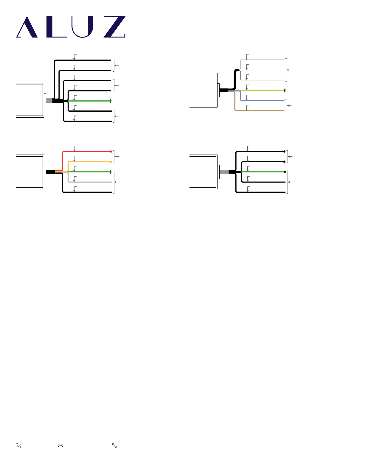
• Do not make wiring connections without referring to wiring diagrams.
• Do not cut wire while energized.
(Fig. 2)
• Do not exceed maximum run lengths.
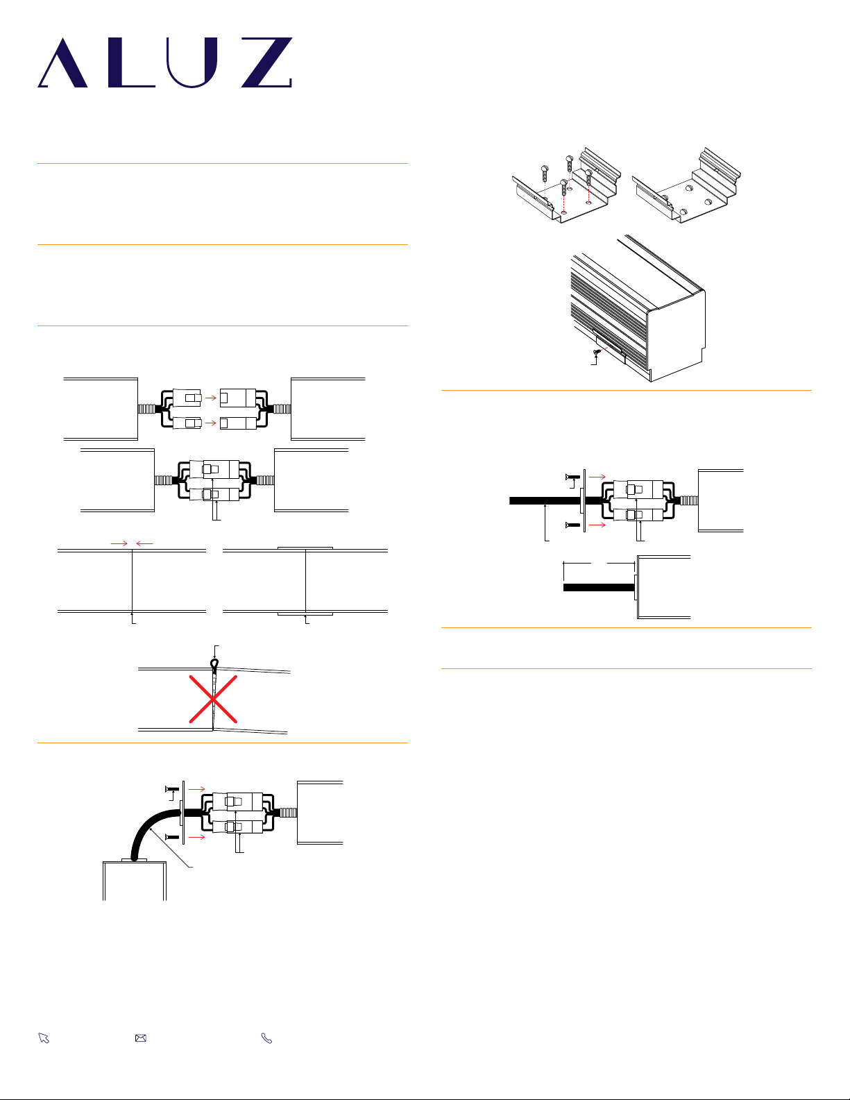
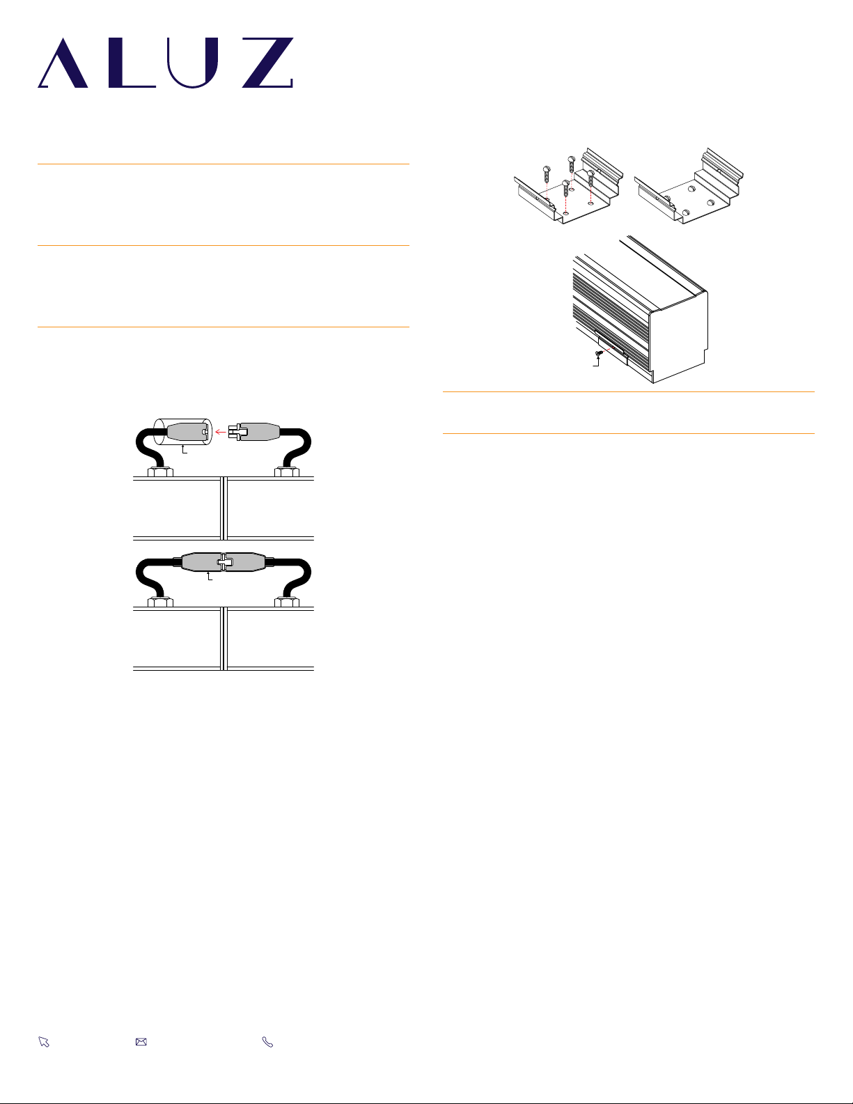
• Always follow sequence labeling for continuous runs. Continuous run segments
are labeled in alphabetical order.
• Polarity of continuous run segments must be aligned.
• Do not assemble continuous runs prior to installing into mounting clips.
Each segment must be installed one by one into mounting clips. The weight of
the assembled segments will put strain on junctions, causing the board, pin, or
terminals to break.
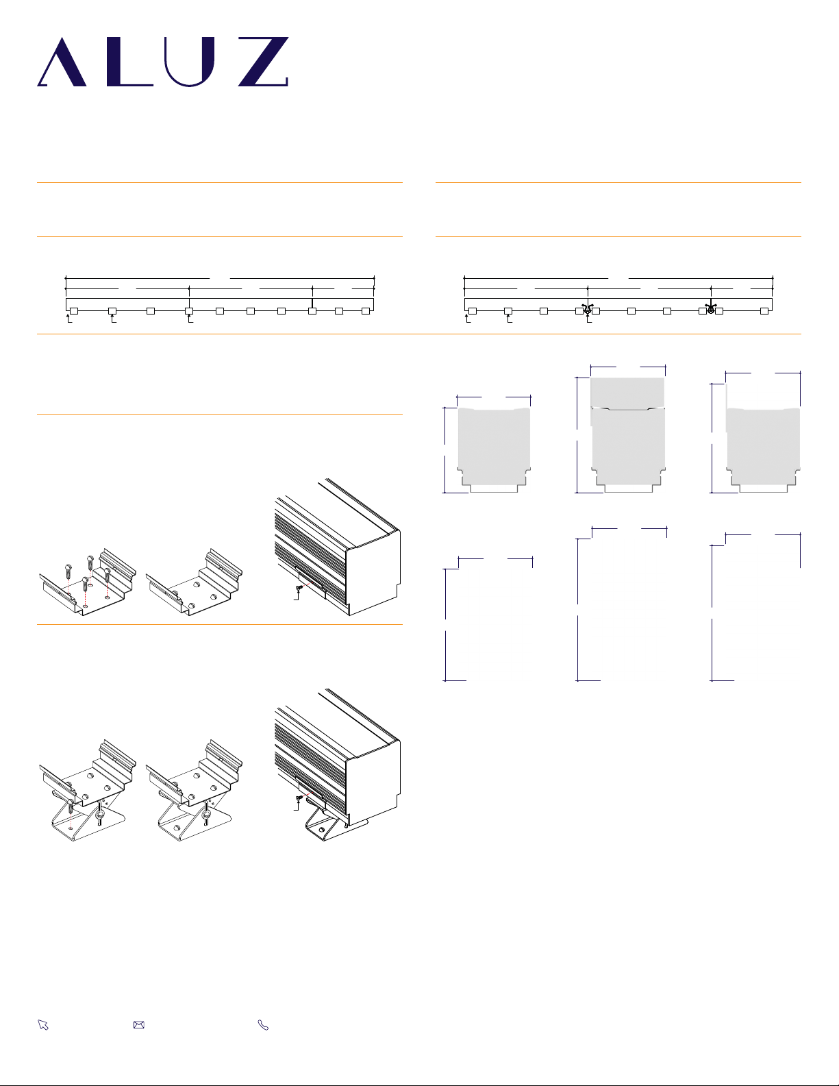
• Do not install continuous runs without a mounting clip at each junction between
two segments.
• Do not secure luminaire with nails or like means that might damage the wiring
inside. Only secure by using mounting clips.
• Do not mount luminaire inside tanks or enclosures of any kind.
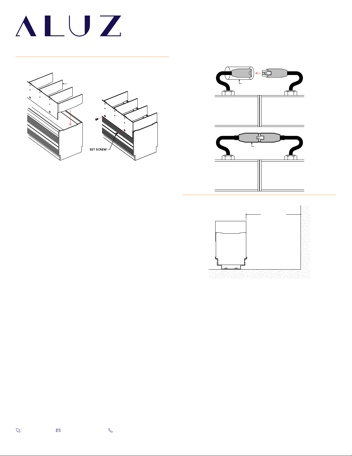
• Do not install downward facing luminaires without set screws.
• Do not use improper screw head type on mounting clips. It will cause the
mounting clip to open up and become dysfunctional.
• Do not modify mounting clips.
• Do not weld mounting clips to surface. Mounting clips must be mechanically
attached with screws appropriate for mounting surface and weight of luminaire.
• Do not mount fixture with less than the minimum number of mounting clips
required. See mounting clips section for details.
• Do not install mounting clips on uneven surfaces. Use shims to level out height
of mounting clips if necessary.
• Do not install mounting clips after luminaires have been assembled.
Install mounting clips first, then install luminaire into mounting clips.
• Do not force luminaire into a space that is too small.
• Do not force luminaire with cord grip into soffit.
(Fig. 3)
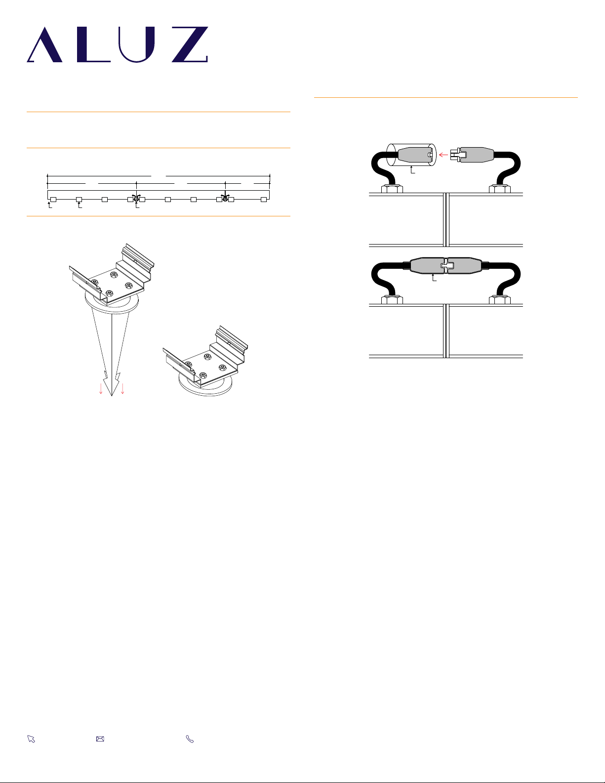
• Do not install luminaire at an angle within a cove. Only install fixtures straight
within a cove. (Fig. 4)
• Do not bend extrusion around radius.
• Do not submerge dry or wet location luminaire in any liquid.
• Do not install wet location in outdoor coves without proper drainage.
(Fig. 5)
• Do not install luminaire in any area that is continuously exposed to flowing or
pooling water, such as underneath drain pipes, sprinklers, fountains, misters, etc.
• Do not cut, puncture, or penetrate aluminum housing, end caps, or lens covers.
• Do not drop, bang, or rest weight upon luminaire.
• Do not apply excessive pressure to any part of luminaire.
• Do not remove end caps from luminaire.
• Do not bend power cord or continuous connector past permitted bend radius.
Bending past permitted bend radius will break the seal of the cordgrip or
damage the insulation. (Fig. 6)
Wet Location: 3.5” minimum bend radius
Dry Location: 1.5” minimum bend radius
• Do not install in places where the power cord is subject to continuous flexing.
• Do not twist continuous connector or power cord.
• Do not hold, carry, or suspend luminaire by the power cord.
• Do not install on ceilings without mounting clips and set screws.
(Fig. 7)
When using luminaires for any application, basic safety precautions
should always be followed to reduce the risk of fire, electric shock, and
personal injury. Luminaires must be installed in accordance with the
NEC or CEC as applicable. ALUZ will not be responsible for damage or
malfunction caused by the following:
WARNING FIGURES
INCORRECT
CORRECT
Figure 1
INCORRECT CORRECT
Figure 5
INCORRECT CORRECT
Figure 6
MOUNTING CLIP
SET SCREW
Figure 7
Figure 2
INCORRECT
CORRECT
Figure 3
INCORRECT
CORRECT
Figure 4
CLEANING MATERIALS
The use of solvents and/or cleaners which are not compatible with
polycarbonate will result in the softening, crazing, and/or cracking
of the plastic part. This is especially true of polycarbonate lamps
and mounting bases which may be under stress in their normal
applications.
COMPATIBLE WITH POLYCARBONATE
• Mild soap and water
• Mineral Spirits
• Isobutyl Alcohol
• VM and P Naphtha
• Varsol No.2
• Mexane
• Freone TF and TE-35
• Ethanol
• Dirtex
• 2% Sol. Reg. Joy
• 10% Sol Bon Ami
• White Kerosene
• Methyl Alcohol
• Heptane
• Petroleum Ether / 65°C
• Isopropyl Alcohol
• Lacryl PCL-2035
Polycarbonate Cleaner
NOT COMPATIBLE WITH POLYCARBONATE
• Trichlor
• Gasoline
• Liquid Detergents
• Acetone
• Carbon Tetrachloride
• Pink Lux (Phosphate free)
• Triclene
• Chlorinated Hydrocarbons
• #1 & #3 Denatured Alcohol
• Methyl Ethyl Keytone (MEK)
• Texize-8006, 8129, 8758
• MIBK
• Liquid Cleaner – 8211
• Toluol
• Agitene
• Benzol
• Ajax
• Kleenol Plastics
• Lysol
• Stanisol Naphtha
• Oils
• Lemon Joy (phosphate free)
• Diversol
• Lestoil

Installation Instructions
1170 N Red Gum St, Anaheim, CA 92806
© ALUZ All Rights Reserved. ALUZ reserves the right to make changes or withdraw specifications without prior notice.
A1 Series |Surface
ZIBI Standard Dynamic White
(A1-ZIBI-STN-DWH)
Page 3 of 13
9 / 11 / 2023 / Rev 4
Wiring Diagrams
Note: Verify wire colors and wiring diagram from fixture before connecting. If there is a discrepancy, consult factory before connecting.
DALI
(Dry Location)
PRIMARY VOLTAGE
120-277VAC
TO DALI CONTROLS
GROUND (GREEN)
DALI+ (RED)
DALI- (ORANGE)
NEUTRAL (WHITE)
HOT (BLACK)
Note:
18/5 Gauge Wire. Outer jacket measures .45”. Individual jackets measure .10”
DALI (Wet Location)
PRIMARY VOLTAGE
120-277VAC
TO DALI CONTROLS
GROUND (GREEN)
DALI+ (WIRE 3)
DALI- (WIRE 4)
NEUTRAL (WIRE 2)
HOT (WIRE 1)
Note: 18/5 Gauge Wire. Outer jacket measures .45”. Individual jackets measure .10”
PRIMARY VOLTAGE
120-277VAC
CCT CONTROLS
INTENSITY
CONTROLS
GROUND (GREEN)
10V+ (WIRE 3)
10V- (WIRE 4)
10V+ (WIRE 5)
10V- (WIRE 6)
NEUTRAL (WIRE 2)
HOT (WIRE 1)
0-10V (Dry & Wet Location)
Note:
18/7 Gauge Wire. Outer jacket measures .45”. Individual jackets measure .10”
DMX+ (WHITE)
DMX- (BLUE)
DMX SHIELD (SLEEVE)
GROUND (GREEN/YELLOW)
NEUTRAL (BLUE)
HOT (BROWN)
PRIMARY VOLTAGE
120-277VAC
DMX SIGNAL
DMX (Dry or Wet Location)
Note: 18/5 Gauge Wire. Outer jacket measures .34”. Individual jackets measure .13”
• Consult third party DMX commissioner to modify at time of installation.
• Connection from DMX controller to luminaire must be made using a
proper daisy chain connection per DMX-512 / RDM standards.
• Do not make DMX wiring connections in parallel.
• When connecting DMX Shield to a DMX controller terminal, ensure that
it is not connected to or touching earth ground, chassis ground, and/or
DC power (-) return.
DMX NOTE
• DALI commissioning to be performed by a third party at time of
installation. ALUZ does not provide DALI commissioning.
DALI NOTE

Installation Instructions
1170 N Red Gum St, Anaheim, CA 92806
© ALUZ All Rights Reserved. ALUZ reserves the right to make changes or withdraw specifications without prior notice.
A1 Series |Surface
ZIBI Standard Dynamic White
(A1-ZIBI-STN-DWH)
Page 4 of 13
9 / 11 / 2023 / Rev 4
Mounting Clips
WET LOCATION APPLICATIONSDRY LOCATION APPLICATIONS
8’
20’
8’ 4’
3” Gap Mounting Clip Junction between luminaire segments
8’
20’
8’ 4’
3” Gap Mounting Clip Junction between luminaire segments
1
Measure area where luminaire will be installed. Use a laser line to
create a reference line along installation area, ensuring consistent
alignment of mounting clips. Mark location where each mounting
clip will be installed along reference line.
1Measure area where luminaire will be installed. Use a laser line to
create a reference line along installation area, ensuring consistent
alignment of mounting clips. Mark location where each mounting
clip will be installed along reference line.
2
Use 1 mounting clip every 2’, rounded up. Use a minimum of 2
mounting clips per fixture segment. For vertical applications, create
a stopper at the bottom of the run to prevent sliding.
2Use 1 mounting clip every 2’, rounded up. Use a minimum of 2
mounting clips per fixture segment. For vertical applications, create
a stopper at the bottom of the run to prevent sliding.
3
Use a mounting clip at the junction between two fixture segments.
Example: 20’ Run.
4
Lay mounting clips along reference line and pre-drill using an
appropriate drill bit for surface material and screw size.
Typical screw size is 8/32 x 1”.
Note: Allow 1/4” clearance on each side of mounting clip due to
lateral expansion. Only install mounting clips on flat, even surfaces.
3Space mounting clips evenly throughout the run.
Example: 20’ Run.
SET SCREW
SET SCREW
2.55”
2.97”
MC
2.55”
3.98”
MC-3
2.60”
3.98”
MC with Louver
2.60”
4.99”
MC-3 with Louver
2.60”
3.98”
MC with Reflector
2.60”
4.99”
MC-3 with Reflector
ASSEMBLED DIMENSIONS
5
Screw mounting clips to surface, then snap luminaire into mounting
clips. Install set screws to each mounting clip, if applicable. Set screws
are required for downward facing, outward facing, and vertically
mounted applications.
6
Screw mounting clips to surface, then snap luminaire into mounting
clips. Install set screws to each mounting clip, if applicable. Set screws
are required for downward facing, outward facing, and vertically
mounted applications.

Installation Instructions
1170 N Red Gum St, Anaheim, CA 92806
© ALUZ All Rights Reserved. ALUZ reserves the right to make changes or withdraw specifications without prior notice.
A1 Series |Surface
ZIBI Standard Dynamic White
(A1-ZIBI-STN-DWH)
Page 5 of 13
9 / 11 / 2023 / Rev 4
Stake Mounting Clip
5Ensure each stake is secured in place, then snap luminaires into
mounting clips.
4
Insert stakes into ground until entire tapered portion is submerged.
Note: The ground must be able to support the weight of luminaires.
SHRINK TUBE
APPLY HEAT
6If applicable, connect disconnects between luminaires. Slide
shrink tube over connectors and apply heat. The shrink tube will
shrink down, sealing the connectors. Apply silicone around sealed
connectors for a stronger seal.
8’
20’
8’ 4’
3” Gap Mounting Clip Junction between luminaire segments
1Measure area where luminaire will be installed. Use a laser line to create
a reference line along installation area, ensuring consistent alignment of
mounting clips. Mark location where each mounting clip will be installed
along reference line.
2
Use 1 mounting clip every 2’, rounded up. Use a minimum of 2 mounting clips
per luminaire segment. For vertical applications, create a stopper at the
bottom of the run to prevent sliding.
3
Space mounting clips evenly throughout the run.
Example: 20’ Run.

Installation Instructions
1170 N Red Gum St, Anaheim, CA 92806
© ALUZ All Rights Reserved. ALUZ reserves the right to make changes or withdraw specifications without prior notice.
A1 Series |Surface
ZIBI Standard Dynamic White
(A1-ZIBI-STN-DWH)
Page 6 of 13
9 / 11 / 2023 / Rev 4
Dry Location Mounting
SET SCREW
ENSURE CONNECTIONS
ARE SECURE
END CAP SCREWS
JUMPER CABLE
(1.75” MINIMUM BEND RADIUS)
ENSURE CONNECTIONS
ARE SECURE
PUSH TOGETHER,
LEAVING NO GAP
MOUNTING CLIP HOLDS
SEGMENTS TOGETHER
DO NOT LEAVE GAPS
OR PINCH WIRES
POWER CONNECTOR
END CAP SCREWS
ENSURE CONNECTIONS
ARE SECURE
6’
1Measure area where luminaire will be installed. Use a laser line
to create a reference along installation area, ensuring accurate
placement of mounting clips. Mark location where each mounting
clip will be installed along reference line.
6Screw mounting clips to surface, then snap luminaire into mounting
clips. Install set screws if required. Set screws are required for
downward and outward facing applications.
7
If applicable, connect power cord disconnects to luminaire segment.
Install end cap screws to connect end cap to segment.
Note:
Standard luminaire provided with 1 factory installed 6’ power
cord and 1 end cap at the end of each run. Power cord is easily
relocated by unscrewing end cap and undoing disconnects.
8Perform a continuity test before connecting to power source.
Refer to Continuity Test for details.
9Verify wiring diagram, then connect luminaire to power source.
2
The number of required mounting clips differs for dry and wet
location products. Verify number of mounting clips is appropriate
for installation environment before beginning installation. Do not
install luminaires with inadequate number of mounting clips. Refer
to the Mounting Clips page for additional information.
3
Lay mounting clips along reference line and pre-drill surface using
an appropriate drill bit for surface and screw size.
Recommendation: 8/32 x 1” Screw.
Note: Allow 1/4” clearance for lateral expansion of assembled
mounting clips. Only install mounting clips on flat, even surfaces.
4
If applicable, connect disconnects between segments and push
together, leaving no gap. Use a mounting clip at the junction
between two segments.
5
If applicable, connect jumper cable disconnects between segments.
Install end cap screws to connect end cap to segment.

Installation Instructions
1170 N Red Gum St, Anaheim, CA 92806
© ALUZ All Rights Reserved. ALUZ reserves the right to make changes or withdraw specifications without prior notice.
A1 Series |Surface
ZIBI Standard Dynamic White
(A1-ZIBI-STN-DWH)
Page 7 of 13
9 / 11 / 2023 / Rev 4
Wet Location Mounting
1Measure area where luminaire will be installed. Use a laser line
to create a reference along installation area, ensuring accurate
placement of mounting clips. Mark location where each mounting
clip will be installed along reference line.
2
The number of required mounting clips differs for dry and wet
location products. Verify number of mounting clips is appropriate
for installation environment before beginning installation. Do not
install luminaires with inadequate number of mounting clips. Refer
to the Mounting Clips page for additional information.
3
Lay mounting clips along reference line and pre-drill surface using
an appropriate drill bit for surface and screw size.
Recommendation: 8/32 x 1” Screw.
Note: Allow 1/4” clearance for lateral expansion of assembled
mounting clips. Only install mounting clips on flat, even surfaces.
4
If applicable, connect disconnects between luminaire segments.
Slide shrink tube over connectors and apply heat. The shrink tube
will shrink down, sealing the connectors. Apply silicone around
sealed connectors for a stronger seal.
Note: Only use a heat gun to apply heat to shrink tubes. Do not use
an open flame such as a lighter or gas torch.
SHRINK TUBE
APPLY HEAT
SET SCREW
5Screw mounting clips to surface, then snap luminaire into mounting
clips. Install set screws if required. Set screws are required for
downward and outward facing applications.
6Perform a continuity test before connecting to power source.
Refer to Continuity Test for details.
7Verify wiring diagram, then connect luminaire to power source.

Installation Instructions
1170 N Red Gum St, Anaheim, CA 92806
© ALUZ All Rights Reserved. ALUZ reserves the right to make changes or withdraw specifications without prior notice.
A1 Series |Surface
ZIBI Standard Dynamic White
(A1-ZIBI-STN-DWH)
Page 8 of 13
9 / 11 / 2023 / Rev 4
Bottom Mount Adjustable Arm
(A1-ZIBI-STN-AA-BM-X)
ASSEMBLED DIMENSIONS
SPACING DIAGRAMS
1Measure area where luminaire will be installed. Use a laser line to
create a reference line along installation area, ensuring consistent
alignment of mounting arms. Mark location where each mounting
arm will be installed along reference line.
5
Loosen set screw until the mounting plate can move freely. Turn
the mounting plate until desired angle is achieved, then mate the
locking bump with locking hole. Tighten set screw until mounting
plate is secured in place.
Note: Refer to Angle Increments diagram next page.
2
Determine number of mounting arms needed. Use a minimum
of 2 mounting arms per luminaire. Mount arms 6” from center of
mounting plate to the end of luminaire.
Note: Refer to Spacing Diagrams on next page for details.
3
Screw arm base to surface using countersink screws of appropriate
type and length for surface material and weight of fixtures.
4
Secure luminaire to mounting plates by installing provided #6-20
countersink screws through countersink holes in the bottom of the
plate. Ensure luminaire is secured in place and spacing is accurate
according to the Spacing Diagrams.
SHRINK TUBE
APPLY HEAT
6If applicable, connect disconnects between luminaires. Slide
shrink tube over connectors and apply heat. The shrink tube will
shrink down, sealing the connectors. Apply silicone around sealed
connectors for a stronger seal.
LOCKING HOLE
MOUNTING PLATE
LOCKING BUMP
SET SCREW
2.52”
4.42”
X
2.0”
No Accessories
2.60”
5.43”
X
2.0”
With Louver
2.60”
5.43”
X
2.0”
With Reflector
4’
3’-6”3” 3”
Example: 4’ Run
4’
8’
4’
3’-6”3” 3” 3’-6”3” 3”
Example: 8’ Run

Installation Instructions
1170 N Red Gum St, Anaheim, CA 92806
© ALUZ All Rights Reserved. ALUZ reserves the right to make changes or withdraw specifications without prior notice.
A1 Series |Surface
ZIBI Standard Dynamic White
(A1-ZIBI-STN-DWH)
Page 9 of 13
9 / 11 / 2023 / Rev 4
Side Mount Adjustable Arm
(A1-ZIBI-STN-AA-SM-X)
1Measure area where luminaire will be installed. Use a laser line to
create a reference line along installation area, ensuring consistent
alignment of mounting arms. Mark location where each mounting
arm will be installed along reference line.
5
Loosen set screw until the mounting plate can move freely. Turn
the mounting plate until desired angle is achieved, then mate the
locking bump with locking hole. Tighten set screw until mounting
plate is secured in place.
Note: Refer to Angle Increments diagram next page.
2
Determine number of mounting arms needed. Use a minimum
of 2 mounting arms per luminaire. Mount arms 6” from center of
mounting plate to the end of luminaire.
Note: Refer to Spacing Diagrams on next page for details.
3
Screw arm base to surface using countersink screws of appropriate
type and length for surface material and weight of fixtures.
6If applicable, connect disconnects between luminaires. Slide
shrink tube over connectors and apply heat. The shrink tube will
shrink down, sealing the connectors. Apply silicone around sealed
connectors for a stronger seal.
LOCKING BUMP
SET SCREW
LOCKING HOLE
MOUNTING PLATE
4
Secure luminaire to mounting plates by installing provided #6-20
countersink screws through countersink holes in the bottom of the
plate. Ensure luminaire is secured in place and spacing is accurate
according to the Spacing Diagrams.
SHRINK TUBE
APPLY HEAT
ASSEMBLED DIMENSIONS
SPACING DIAGRAMS
4’
3’-6”3” 3”
Example: 4’ Run
4’
8’
4’
3’-6”3” 3” 3’-6”3” 3”
Example: 8’ Run
2.81”
X
2.0”
2.78”
No Accessories
3.82”
X
2.0”
2.86”
With Louver
3.82”
X
2.0”
2.86”
With Reflector

Installation Instructions
1170 N Red Gum St, Anaheim, CA 92806
© ALUZ All Rights Reserved. ALUZ reserves the right to make changes or withdraw specifications without prior notice.
A1 Series |Surface
ZIBI Standard Dynamic White
(A1-ZIBI-STN-DWH)
Page 10 of 13
9 / 11 / 2023 / Rev 4
Louver (A1-ZIBI-STN-LVR)
LOUVER
SET SCREW
MINIMUM 12”
FROM WALL
SHRINK TUBE
APPLY HEAT
1Determine number of louvers needed. Louvers are available in 1’
increments. Specify total length of reflectors needed.
3If applicable, connect disconnects between luminaires. Slide
shrink tube over connectors and apply heat. The shrink tube will
shrink down, sealing the connectors. Apply silicone around sealed
connectors for a stronger seal.
4Mount luminaires at least 12” away from the wall.
2
Position louvers on luminaires, then install 3 set screws on each
louver segment to secure in place. Do not over-tighten set screws

Installation Instructions
1170 N Red Gum St, Anaheim, CA 92806
© ALUZ All Rights Reserved. ALUZ reserves the right to make changes or withdraw specifications without prior notice.
A1 Series |Surface
ZIBI Standard Dynamic White
(A1-ZIBI-STN-DWH)
Page 11 of 13
9 / 11 / 2023 / Rev 4
Reflector (A1-ZIBI-STN-RE1)
REFLECTOR
SET SCREW
MINIMUM 12”
FROM WALL
SHRINK TUBE
APPLY HEAT
1Determine number of reflectors needed. Reflectors are available in
1’, 2’, 3’, or 4’ increments. Specify total length of reflectors needed.
3If applicable, connect disconnects between luminaires. Slide
shrink tube over connectors and apply heat. The shrink tube will
shrink down, sealing the connectors. Apply silicone around sealed
connectors for a stronger seal.
4Mount luminaires at least 12” away from the wall.
2
Position reflectors on luminaires, then install 3 set screws on each
reflector segment to secure in place. Do not over-tighten set screws

Installation Instructions
1170 N Red Gum St, Anaheim, CA 92806
© ALUZ All Rights Reserved. ALUZ reserves the right to make changes or withdraw specifications without prior notice.
A1 Series |Surface
ZIBI Standard Dynamic White
(A1-ZIBI-STN-DWH)
Page 12 of 13
9 / 11 / 2023 / Rev 4
Troubleshooting & Continuity Test
1
2
3 (GROUND)
4
5
RED PROBE
BLACK PROBE
1
2
3 (GROUND)
4
5
RED PROBE
BLACK PROBE
1
2
3 (GROUND)
4
5
RED PROBE
BLACK PROBE
FRAYED END
FOREIGN OBJECT METAL FLAKES
TORN LIGHTSTRIP DAMAGED LIGHTSTRIP
TROUBLESHOOTING TIPS
• Do not reset the breaker multiple times.
• If the unit is overloaded, the breaker will trip, shutting off the driver
and lights.
• If the breaker reset button has been held down by hand or any type of
pressure, such as duct tape, or if the breaker has been reset multiple
times without troubleshooting, the unit will:
- Burn the driver bobbin.
- Burn the thermal or magnetic breaker.
- Burn the driver lead wires due to high amperage caused by overload.
- Short circuit in line which will not allow the breaker to reset.
- Damage the lighting.
12
1
Turn off power before beginning. Check for any twisting or damage
to the circuit in the LED lightstrip. If there is excessive damage and
the circuit is broken, the lightstrip must be replaced.
3Touch the red probe to the luminaire extrusion and the black probe
to the ground wire (green). If the luminaire is properly grounded,
the multimeter will beep, flash, or read 0Ω(ohms). If there is no
conductive path, the multimeter will not show any feedback.
Troubleshoot to identify the malfunction in the ground wire.
4Touch the red probe to any wire and the black probe to each other
wire. Repeat process for each wire. If a conductive path is formed
between any of the wires, the multimeter will beep, flash, or read
0Ω(ohms). Troubleshoot to identify the malfunction in the line.
If there is no conductive path, the multimeter will not show any
feedback.
Example: Check for continuity between Wire 2 and Wire 4
5Touch the red probe to the luminaire housing and the black probe
to each wire except ground. If a conductive path is formed between
the housing and any of the wires, the multimeter will beep, flash,
or read 0Ω(ohms). Troubleshoot to identify the malfunction in the
line. If there is no conductive path, the multimeter will not show
any feedback.
6Set multimeter to AC voltage and test power source. Confirm the
correct voltage before connecting luminaire to power source. If the
voltage reading is more than 1 volt greater than the marked output
voltage, there is a problem with the power source or driver.
7Connect luminaire to power source. If LEDs do not turn on,
troubleshoot to find the problem in the line.
2
Check for metal particles or other foreign objects causing the short.
3
Check to make sure cuts in the lightstrip are clean and not frayed,
causing positive and negative copper pads to touch.
CONTINUITY TEST
A continuity test is performed to determine if electricity can pass
through two points on an electrical circuit. This helps identify shorts
or malfunctions in the luminaire. Use a multimeter or continuity
tester to perform the steps below.
• Always perform a continuity test before connecting to power source.
• Malfunctions are not always as obvious as the lights not turning on.
• A short or malfunction in the line or luminaire will cause damage over
time, irreparably damaging the lighting and voiding warranty.
1
Turn off power before beginning. Verify power is off by using a non-
contact circuit tester (by others). Touch the probe of the tester to
the positive wire of the power source. The tester will light up if an
electrical current is detected.
2
Setup your multimeter tester (by others). First, insert the black
probe lead into the COM jack, then insert the red probe lead into
the VΩjack.

Installation Instructions
1170 N Red Gum St, Anaheim, CA 92806
© ALUZ All Rights Reserved. ALUZ reserves the right to make changes or withdraw specifications without prior notice.
A1 Series |Surface
ZIBI Standard Dynamic White
(A1-ZIBI-STN-DWH)
Page 13 of 13
9 / 11 / 2023 / Rev 4
Surge Protector
SURGE PROTECTOR SPECIFICATIONS
Model Input Voltage Surge Protection Level Mounting Enclosure Material Input Needs Input Frequency
ALS-P 120V - 277V 0kV, 10kA, ANSI C62.41 Category C SnapLOCK / Footed Polycarbonate 6”, 18AWG stranded, 105°C stripped, 3/8” tinned 60Hz
0-10V WIRING DIMMING DIAGRAM
LED LIGHTING
ELECTRONIC
DRIVER
POWER SOURCE
(120 - 277V AC)
HOT (BLACK)
NEUTRAL (WHITE)
DIM+
DIM- 0-10V DIMMER
(BY OTHERS)
GROUND (GREEN)
V-
V+
HOT GROUND
NEUTRAL
SURGE PROTECTOR
FORWARD / REVERSE PHASE DIMMING WIRING DIAGRAM
LED LIGHTING
ELECTRONIC DRIVER
POWER SOURCE
(120-277VAC)
CAP OFF 10V DIMMING WIRES
HOT (BLACK)NEUTRAL (WHITE)
FORWARD OR REVERSE
PHASE DIMMER
(BY OTHERS)
LINE HOT
NEUTRAL
GROUND (GREEN)
GROUND
DIM+
DIM-
V+
V-
SURGE PROTECTOR
1.0”
1.52”
.26”
.26”
.25”ø 1.14”
.41”
2.91”
1.91”
1.16”
.09”
.58”
CASE DIMENSIONS
The Surge Series are 3-leaded devices that protect Line-Ground, Line-
Neutral, and Neutral-Ground in accordance with IEEE / ANSI C62.41.2
guidelines. Protects against surges according to IE EE C62.41.2 C High
(10kA and 10kV). Surge current rating = 10,000 Amps using industry
standard 8/20 �Sec wave. Surge Location Rated Category C3. UL
Recognized Component in the United States and Canada (UL1449).
Type 4 Surge Protection Device. High temperature, flame retardant
plastic enclosure, 85°C maximum surface temperature rating. Thermally
Protected Transient Over-voltage Circuit.
PRODUCT FEATURES
The Surge series of products are designed to be used in conjunction
with LED Drivers and fixtures to provide an additional level of
protection against powerline disturbances in industrial, commercial
and residential applications where surge protection to IEEE C62.41.2 is
required.
PRODUCT SPECIFICATIONS
This manual suits for next models
1
Table of contents
Other ALUZ Lighting Equipment manuals

ALUZ
ALUZ ZIBI A1 Series User manual

ALUZ
ALUZ A1-ZYZY-SQR User manual

ALUZ
ALUZ A8-ZIZA-SOP User manual

ALUZ
ALUZ A8 Series User manual

ALUZ
ALUZ A8 Series User manual

ALUZ
ALUZ A8-ZIZA-TAPE User manual

ALUZ
ALUZ ZIBI A1 Series User manual

ALUZ
ALUZ A8 Series User manual

ALUZ
ALUZ ZIBI A1 Series User manual

ALUZ
ALUZ ZIBI A1 Series User manual