Installation Cut Sheet
3 / 7 / 2022 / Rev 0
Page 2 of 2
1170 North Red Gum Street, Anaheim, CA 92806
© ALUZ All rights reserved. ALUZ reserves the right to make changes or withdraw specifications without prior notice.
A8 Series |LED Tape
CONNECTOR Dry Continuous Connector
(A8-CC-3P-DRY)
This document is issued in strict confidence on condition that it is not used as
a basis for manufacture or sale and is not copied, reprinted, or disclosed to a
third party either wholly or in part without the prior written consent of ALUZ.
Dry Continuous Connector
20/3 Gauge Wire
(A8-CC-3P-DRY-X)
X = Specify Length, 3” Default
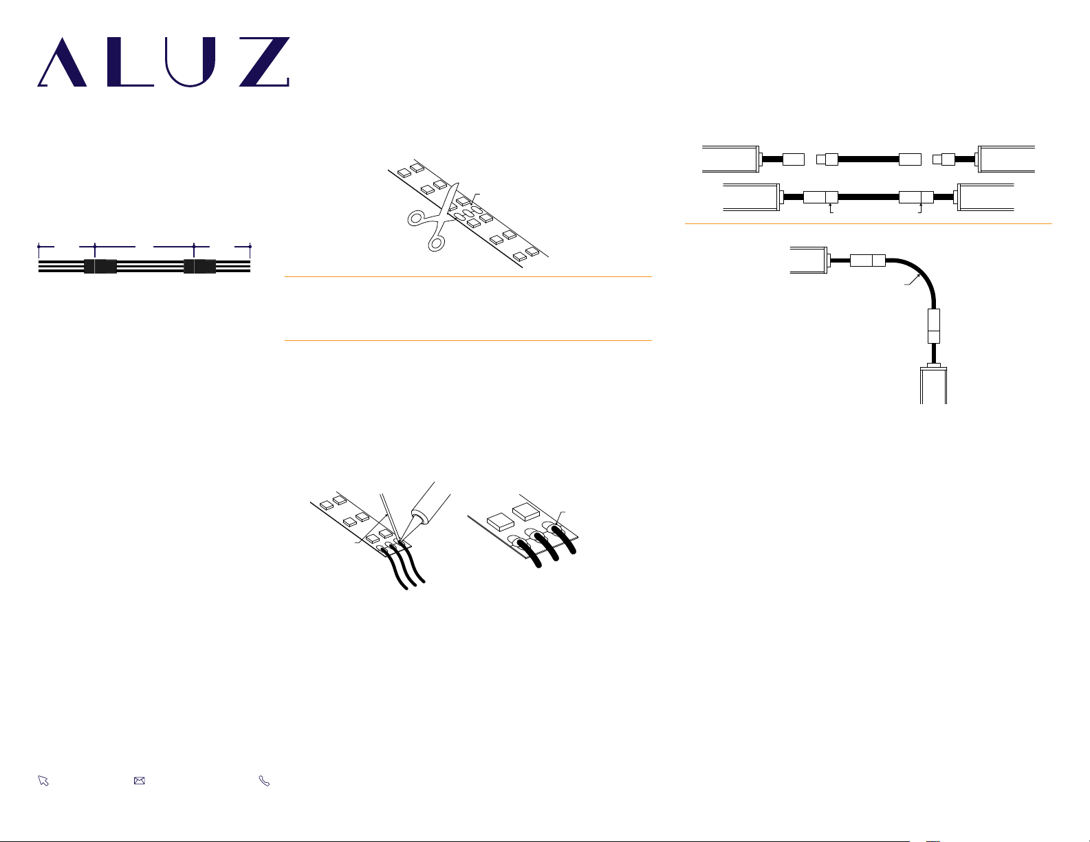
POSITION WIRES
1
After soldering is completed, make connections between connectors
by plugging the male and female disconnects together.
2Position connectors as needed.
Note: Appearance of lightstrip may differ from example shown.
Refer to wiring diagrams before soldering any wires.
ZOMU SOLDERING GUIDE
CUT TO SIZE
WELLER 0.50”
WIRE AND PADS
Cut lightstrip to desired length. Include both sets of solder pads by
cutting to the left or right of designated markings, allowing more
space for soldering.
Prepare wires by stripping 1/8” from the end of each wire, then tin
the tips of the wire with solder. Apply heat to stripped portion of
wire, then add a small amount of solder until stripped portion of
wire is fully covered in solder.
Solder lead wires to solder pads on the end of lightstrip.
• Solder the Brown wire to the pad marked “+”.
• Solder the White wire to the pad marked “W”.
• Solder the Yellow wire to the pad marked “WW”.
Note: Solder iron not to exceed 720°F. Heat joint with tip of iron.
Heat both the solder pad and the wire. Add a small drop of solder
on the tip of solder iron to transfer the heat to joint quickly; it
should melt and flow smoothly, covering the wire and pad.
Remove iron once enough solder has been added to the
components. Allow 5 seconds for the joint to cool.


