ALVEO3D PrinterCase User manual

ALVEO3D
INSTRUCTION
MANUAL
v1.0 EN
PrinterCase - 526563
3D printer enclosure with air filtering - HEPA13 & active carbon
Find assembly video on
www.alveo3d.com/en/assembly-printercase/
and download contents
www.alveo3d.com/en/download-printercase/

PROVIDED ELEMENTS p. 3-4
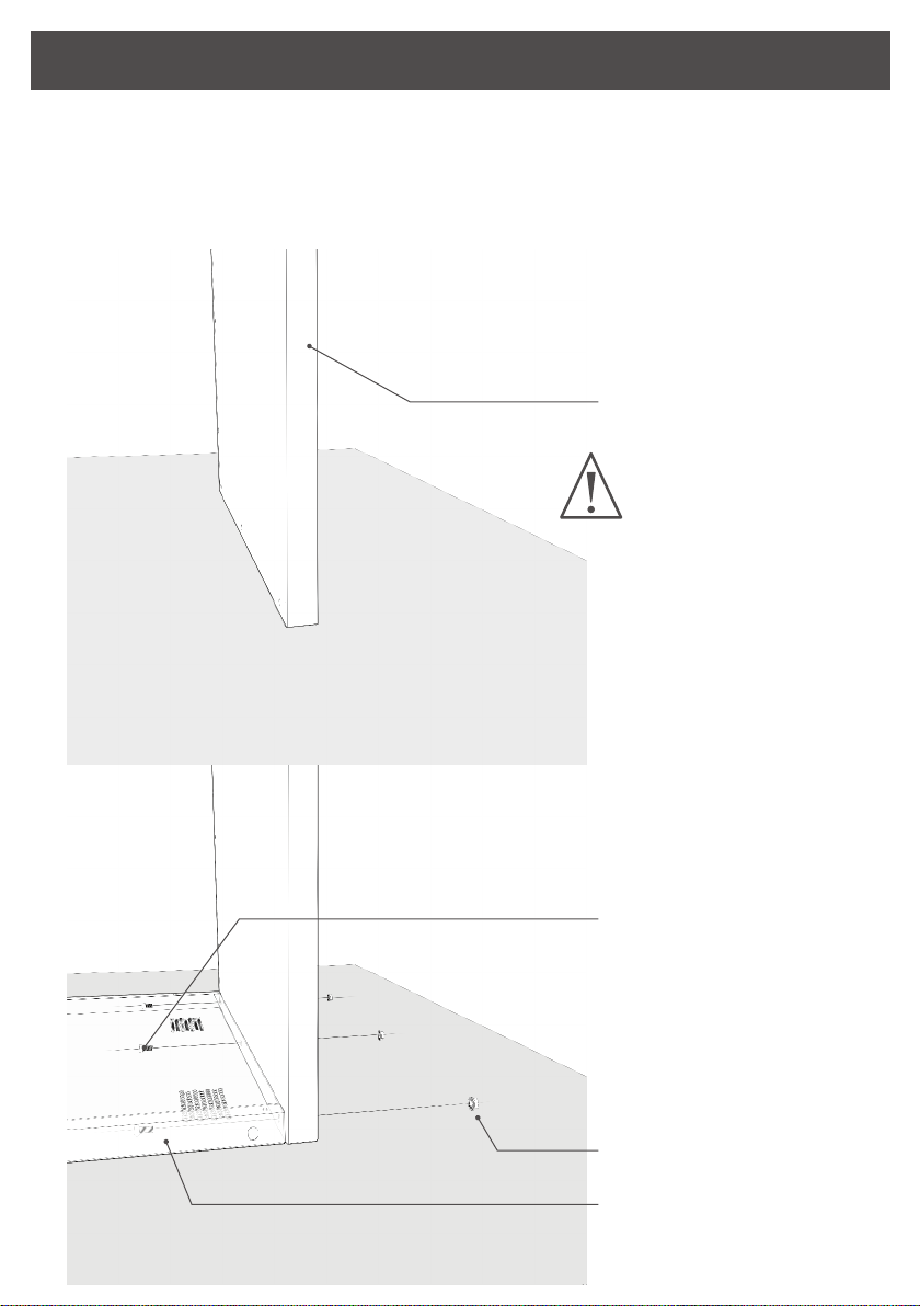
STEP 6 - FEET INSTALLATION p. 11
STEP 7 - FILTERING SYSTEM p. 12
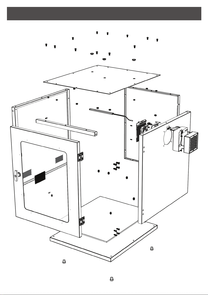
PRINTERCASE - 526563 p. 5
STEP 7.1 - ALVEOZERO BOARD DETAIL p. 13
STEP 2 - BOTTOM AND LEFT PANELS p. 7
STEP 7.2 - FILTERING SYSTEM PREPARATION p. 14
STEP 3 - BACK PANEL p. 8
STEP 7.3 - MOUNTING FILTERING SYSTEM p. 15
STEP 4 - PASSAGEWAY CABLE p. 9
STEP 8 - AIR INTAKE GRIDS p. 17
STEP 5 - RIGHT PANEL p. 10
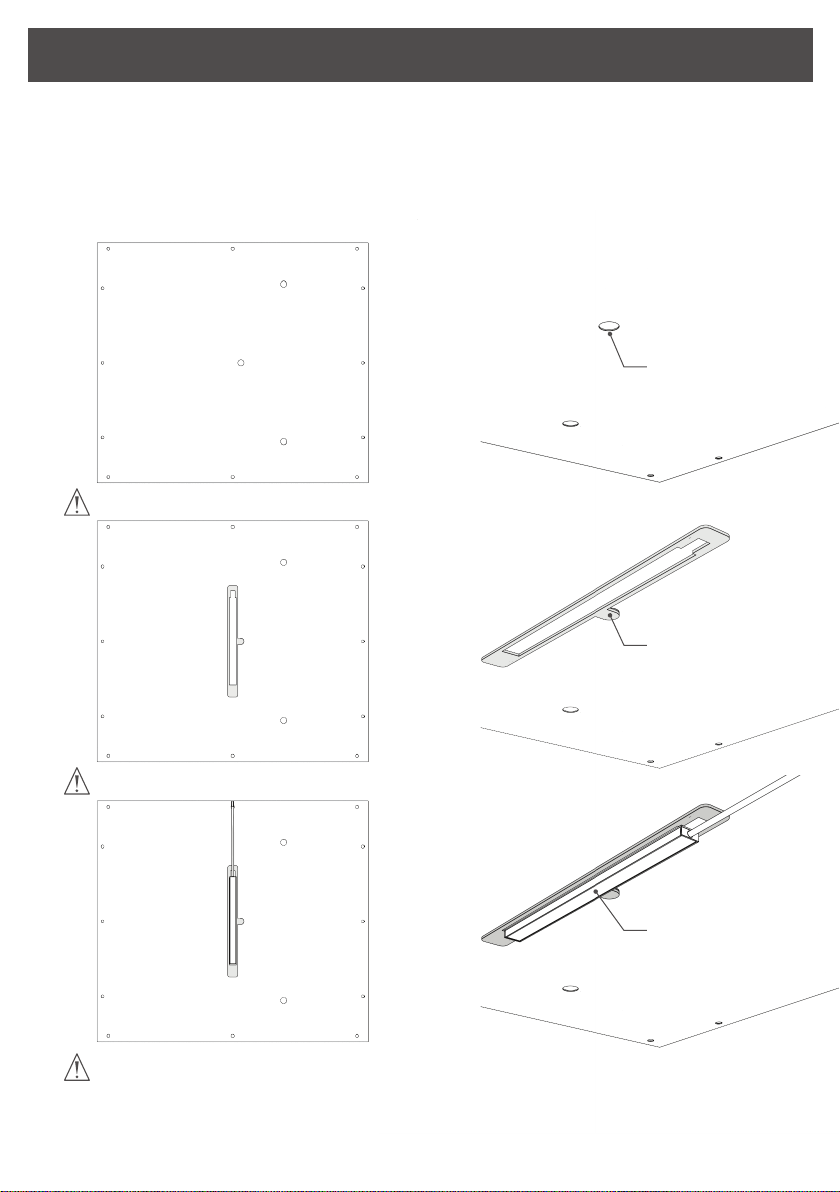
STEP 1 - LED LIGHT POSITIONING p. 6
STEP 10 - TOP PANEL STRENGTH SUPPORT p. 19
TABLE OF CONTENTS p. 1
SAFETY INSTRUCTIONS p. 2
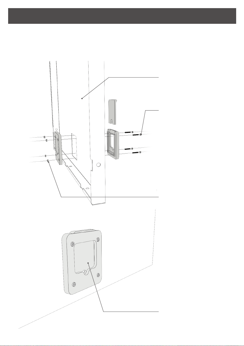
STEP 13 - LOCK SUPPORT p. 22
STEP 15 - LOCK p. 24
STEP 17 - SETTING LOCK SUPPORT p. 26
STEP 7.4 - ASSEMBLY CHECKPOINT p. 16
STEP 9 - INSULATING FOAM p. 18
STEP 11 - LED LIGHT CONNECTING p. 20
STEP 12 - ASSEMBLY TOP PANEL p. 21
STEP 14 - DOOR p. 23
STEP 16 - DOOR SEAL p. 25
STEP 18 - FILTER INSTALLATION p. 27
STEP 20 - DOOR ALIGNMENT p. 29
STEP 21 - CAPS AND FILAMENT GUIDE p. 30
STEP 19 - POWER SUPPLY p. 28
STEP 22 - OPTION CONTROLLER BOARD V2 p. 31
TABLE OF CONTENTS
01

SAFETY INSTRUCTIONS
Read safety instructions before use
3D printer enclosures contain harmful emissions from 3D
printing. It is advised to always turn the filtering system on
during the printing process.
The filtering system is powered by a high-pressure fan. Do not
turn on the fan before full assembly done with the protective
grid and the P3D filter. Failure to comply with this instruction
can cause injuries.
Please use recommanded electrical voltages to power electronic
board, as indicated in the assembly instructions to prevent
damage.
Do not touch the electronic board in operation.
Make sure the Printercase does not interfere with the full
motion of your 3D printer axis, after it is placed in the enclosure.
Filter operational range 0-60°C max
Clean antidust grids with a moist cloth.
For cleaning inside the Printercase, wear single-use gloves.
02

PROVIDED ELEMENTS
Provided elements in the kit Printercase - 526563
Lock
2x Door centering pins
4x Adjustable feet
15x Screw M6 12 mm round head
8x Screw M6 16 mm countersunk head
15x HEX Flange nut M6
4x Screw M5 10 mm flat head
Insulating foam 615mm x 525mm x 9mm
Lock support
Top Panel
Left Panel
Right Panel
Back Panel
Door
Top panel support
Bottom Panel
03

PROVIDED ELEMENTS
Provided elements in the accessories box
4x HEX Nuts M3
2x Magnetic grids
LED light
Light positioning template
Passageway cable - 3 printed elements
Electronic board Alveozero
Fan - ALHPH2425 - H6
Filter P3D HEPA & active carbon
Power supply 24v
Sealing cord 120mm
4x Anti-slippery pads
Filtering system case - 3 printed elements
2x Caps and 1 filament guide
4x Screw M3 12 mm cylindrical head
Wrench socket 10 mm
Open-end wrench 10 mm
Allen keys 2,5 mm and 4 mm
12x Screw M6 12 mm domed head
8x Fan screw M5 12 mm countersunk head
Door seal strips 2x 650 mm and 2x 580 mm
Screwdriver PH2
04

05
PRINTERCASE - 526563

06
Use the light positioning template to centering the LED light. Put he light
positioning template in the middle hole as the drawing below.
Stick the self-adhesive tape at the back of the light to the top panel.
The LED light must be fixed on the side which you want to be inside the
enclosure.
STEP 1 . LED LIGHT POSITIONING
Middle hole
Light template
positioning
Put the light
Top panel can be used on both side
Follow the drawing below to place the light positioning template
Be careful to place the light wire in the right direction
to avoid issue for the next assembling step.

07
Begin with the bottom panel. Find the front and place it at
90° on the work plan. Bring the left panel.
STEP 2 . BOTTOM AND LEFT PANELS
Bottom panel
On the bottom panel,
the front side does
not have holes.
3x Nuts HEXA M6
3x Screws round head
M6 12mm
Left panel
Left
Bottom
Front
Come with the inner left
panel. Align both panels
and screw them.

08
Put the back panel on the side (The passageway cable cut towards the bottom
panel). Place all 6 screws between the left panel and the back panel then with
the bottom panel.
Tighten strongly back/bottom panels in the step 5, not now.
STEP 3 . BACK PANEL
Back panel
3x Screw round head
M6 12mm
3x Screws round head
M6 12mm
Tighten the round head
cruciform type M6 screw
with the hexagonal flange
nut.

09
Mount the passageway cable on the back panel. 3 elements printed in green.
STEP 4 . PASSAGEWAY CABLE
Back panel
4x Screws M3
cylindrical head 12 mm
4x Hexagonal nuts M3
Put the sliding door in the
passageway cable.
It must move freely.
Insert nuts in their spots
and tighten green
elements on both sides of
the panel.

10
Place the right panel with the filtering system cutting towards the top.
STEP 5 . RIGHT PANEL
Bottom panel
Right panel
6x Screws round head M6 12mm
Tighten the right panel
with the back panel then
with the bottom panel.
Tighten strongly all
screws, begin with back
and bottom then left and
right. Use the flat wrench
to hold the nuts.

11
Screw all feet as far as it will go.
If needed, you can stick the anti-slippery pads under the feet.
STEP 6 . FEET INSTALLATION
Feet

12
STEP 7 . FILTERING SYTEM
Electronic board
Alveozero
Fan box
Fan
Sealing cord 120 mm
Protective grid
Filter box
8x Fan screws M5
12 mm countersunk head
Fan screws do not need
nuts, they are self-drilling

13
Power switch turns on the filtering system. Lighting switch turns on the light.
The board has 3 connectors : Fan, Light and board V2 (which requires the fan
ALHP2425-H8 to control the system).
STEP 7.1 . ALVEOZERO BOARD DETAIL
POWER ON/OFF Lighting ON/OFF
Connector
V2
Connector
Light
Connector
Fan

14
Take the filter box, electronic board, sealing cord 12 cm, the fan box and the
fan.
STEP 7.2 . FILTERING SYSTEM PREPARATION
Put the electronic board
Alveozero. You must see
the symbol at the
bottom of the board.
Pass the fan cable through
the duct.
Install the sealing cord.
Cut it if needed.
Place the fan, do not pinch
the fan wire while assembling.
Fan box
Filter box
Put the fan label towards
the filter side.

15
Follow the next steps to install the filtering system. Handle the electronic board
with care during assembling.
In picture 2 : Put the electronic board in the hole from the bottom to the top.
STEP 7.3 . MOUNTING FILTERING SYSTEM
Right panel
Screw the filter box to the fan
through the right panel
Put the filter box
on the right panel
Take the fan box
Plug the fan to the 4 pins «FAN»
Fix the grid
1.
2.
3.
4.
5.
6.

16
4 panels assembly : bottom, left, back, and right : 15 screws and nuts
Accessories : passageway cable, filtering system and feet
STEP 7.4 . ASSEMBLY CHECKPOINT
Filtering system
Passageway cable
Feet

17
Put the air intake magnetic grids on the left panel.
STEP 8 . AIR INTAKE GRIDS
Left panel
Magnetic grid

18
Place the insulating foam on the bottom panel. Remove the self-adhesive
protective film and stick it from the bottom to the front.
STEP 9 . INSULATING FOAM
Bottom panel
Insulating foam 9 mm
Center the foam on the
bottom panel from each
panel's edges.

19
Find the fixed nuts on the frame of each panels then place the strength
support.
STEP 10 . TOP PANEL STRENGTH SUPPORT
Fixed nut
2x Screw flat head
M5 10mm
Strength support
Screw the strength support
and tingthen the screws.
This manual suits for next models
1
Table of contents
Other ALVEO3D 3D Printer manuals