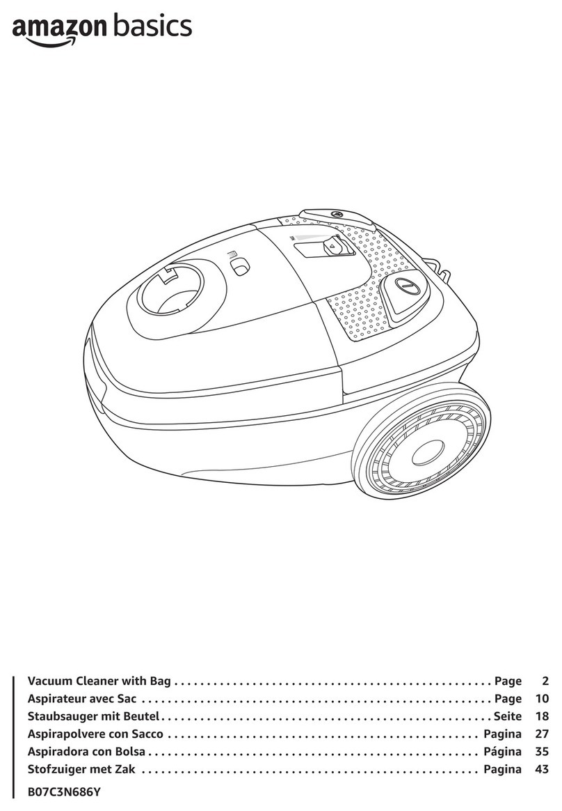
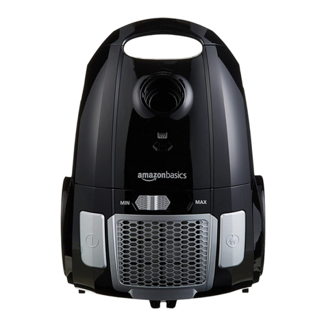
AmazonBasics B07C3N686Y Installation and operating manual

EN . . . . . . . . . . . . . . . . . . . . Page 2
FR . . . . . . . . . . . . . . . . . . . . Page 44
Vacuum Cleaner with Bag
Aspirateur Avec Sac
B07C3N686Y
Professional Service and Repair Manual
Manuel de maintenance et de réparation professionnelles
DANGER
This service and repair manual is intended for professional repairer only. It is
not intended for non-skilled persons. This service and repair manual does not
contain any legal warnings or safety precautions to advise non-skilled persons
of potential dangers which may arise during repair or service.
Any attempt to service or repair the appliance for which this manual is intended by non-skilled
persons may result in serious injury or death.
Do not attempt to service or repair this appliance before reading this manual.
Professional repairer is a person that have the necessary technical competence, and who
complies with all regulations for electrical equipment repairers in their respective country.
DANGER
Ce manuel de maintenance et de réparation est destiné aux réparateurs
professionnels uniquement. Il n’est pas destiné à des personnes non qualiées.
Ce manuel de maintenance et de réparation ne contient pas d’avertissements
légaux ou de précautions de sécurité visant à informer les personnes non
qualiées des dangers potentiels qui peuvent survenir lors de la réparation ou
de la maintenance.
Toute tentative de maintenance ou de réparation de l'appareil, pour lequel ce manuel est prévu,
par des personnes non qualiées peut occasionner des blessures graves, voire mortelles.
Ne tentez pas d'entretenir ou de réparer cet appareil avant d'avoir lu ce manuel.
Un réparateur professionnel est une personne qui possède les compétences techniques
nécessaires et qui respecte toutes les réglementations relatives aux réparateurs d'équipements
électriques en vigueur dans son pays.
DISCLAIMER
Amazon EU S.à r.l. and Amazon EU SARL, UK Branch are not liable
for any damage to the appliance, damages to property, any injury,
or any other appliance safety issue caused by a repair which does
not follow this service and repair manual. Any damages to the
appliance caused by a repair by anyone other than a professional
repairer will also not be covered by the warranty.
AVIS DE NON-
RESPONSABILITÉ
Amazon EU S.à r.l. et Amazon EU SARL, liale Royaume-Uni, ne
sont pas responsables des dommages causés à l’appareil, des
dommages matériels, des blessures ou de tout autre problème
de sécurité de l’appareil occasionnés par toute réparation non
conforme à ce manuel de maintenance et de réparation. Tout
dommage occasionné à l’appareil par une réparation eectuée par
une personne autre qu’un réparateur professionnel ne sera pas non
plus couvert par la garantie.

ENEN
Table of Contents
1. Important Safety Instructions ...................................................................................................................................................................................................... 3
1.1 Explanation of signal words ..................................................................................................................................................................................................... 3
1.2 General safety instructions ...................................................................................................................................................................................................... 3
2. Specifications .................................................................................................................................................................................................................................... 3
3. Spare Parts ........................................................................................................................................................................................................................................ 4
3.1 Repair parts ................................................................................................................................................................................................................................. 4
3.2 Sale parts ..................................................................................................................................................................................................................................... 4
4. Tools Required .................................................................................................................................................................................................................................. 5
5. Electrical Diagram ........................................................................................................................................................................................................................... 5
6. Exploded View - Parts List ............................................................................................................................................................................................................. 6
7. Exploded View .................................................................................................................................................................................................................................. 8
8. Troubleshooting ............................................................................................................................................................................................................................... 9
8.1 The appliance does not switch on. ......................................................................................................................................................................................... 9
8.2 The suction power has reduced. ............................................................................................................................................................................................. 9
8.3 The appliance emits excessive noise. ................................................................................................................................................................................... 10
8.4 There is a burning smell from the appliance. ..................................................................................................................................................................... 10
8.5 The cord winder does not rewind the supply cord into the storage compartment while pressing the cable winder button. .......................... 10
9. Repair/Replacement Instructions ............................................................................................................................................................................................. 11
9.1 Opening the housing .............................................................................................................................................................................................................. 11
9.2 On/o switch replacement .................................................................................................................................................................................................... 16
9.3 Motor replacement .................................................................................................................................................................................................................. 20
9.4 Cord winder assembly replacement ..................................................................................................................................................................................... 25
9.5 PCB assembly replacement .................................................................................................................................................................................................... 32
9.6 Closing the housing ................................................................................................................................................................................................................. 35
10. Functional Test ............................................................................................................................................................................................................................. 39
10.1 Power consumption test ...................................................................................................................................................................................................... 39
10.2 Suction power test ................................................................................................................................................................................................................ 40
10.3 Cord winder assembly mechanical test .......................................................................................................................................................................... 41
11. Disposal of Spare Parts .............................................................................................................................................................................................................. 41
12. Annex I - Motor Test Report from Manufacturer ................................................................................................................................................................ 42
2
EN
3
1. Important Safety Instructions
1.1 Explanation of signal words
DANGER Indicates a hazardous situation which, if not avoided,
will result in death or serious injury.
WARNING Indicates a hazardous situation which, if not
avoided, could result in death or serious injury.
CAUTION Indicates a hazardous situation which, if not avoided,
could result in minor or moderate injury.
CAUTION Indicates a hazardous situation which, if not avoided,
could result in possible risk of property damage.
1.2 General safety instructions
DANGER
This service and repair manual is intended for
professional repairer only. It is not intended for non-
skilled persons. This service and repair manual does
not contain any legal warnings or safety precautions
to advise non-skilled persons of potential dangers
which may arise during repair or service.
Any attempt to service or repair the appliance for which this
manual is intended by non-skilled persons may result in serious
injury or death.
Do not attempt to service or repair this appliance before reading
this manual.
Professional repairer is a person that have the necessary
technical competence, and who complies with all regulations for
electrical equipment repairers in their respective country.
WARNING Do not attempt to perform services or repairs to the
appliance which are not mentioned in this manual.
WARNING Do not modify the appliance or any parts of the
appliance. Modifying the appliance can cause unpredictable
operation resulting in injury.
CAUTION Electrical components, logic boards and circuits can
be damaged by electrostatic discharges. Do not touch any
components or logic boards without ESD protection.
CAUTION Before attempting to service or adjust any part of the
appliance, switch the appliance o and disconnect it from the
socket outlet.
2. Specifications
Model number VCB35B15C
Rated voltage 220-240 V~, 50/60 Hz
Power input 630 to 770 W
Protection class Class II
Noise level ≤79 dB(A)
Suction power ≥12.5 kPa (≥140 W)
Bag capacity 1.5 L
Supply cord type H05VVH-F 2x 0.75 mm2
Cord length 5 m
Net weight approx. 3.7 kg
Dimensions (W x H x D) approx. 355 x 209 x 259 mm
(without accessories)

EN
4
3. Spare Parts
WARNING Only use spare parts as indicated in the table below. The use of unauthorized spare parts could cause risk of electric shock, re or
damage to the appliance and will void the warranty.
3.1 Repair parts
Part name Part code Part no. in exploded view Availability Quantity
On/o switch 17475000001065 19 10 years 1
PCB assembly 17475000008441+17175000001896 20 10 years 1
Motor assembly 17475000000824 25 10 years 1
Cord winder assembly 12175000083528 32 10 years 1
3.2 Sale parts
Part name Part code Part no. in exploded view Availability Quantity
Motor lter 12475000000024 2 10 years 1
Paper dust bag 12475000000382 5 10 years 2
HEPA lter 12175000065393 29 10 years 1
Flexible hose 12175000013863 -- 10 years 1
Parquet brush 12175000014064 -- 10 years 1
Extension tube 12975000004773 -- 10 years 1
Upholstery nozzle 12175000003755 -- 10 years 1
Dusting brush 12175000008965 -- 10 years 1
Multi-surface brush 12175000A12359 -- 10 years 1
Crevice tool 12175000001261 -- 10 years 1
Accessory holder 12175000003812 -- 10 years 1
NOTICE For parts not shown in the exploded view, refer to the Appliance Description chapter in the digital user manual for identication.

EN
5
4. Tools Required
5. Electrical Diagram
F2 TCO 105 °C
J2
AC
motor
C1
(0.22 uF
275 V)
230 V~
L
N
S
J1
CON2
2
1
C2
(0.1 uF
400 V)
Q
BTA12 600 V
DB1
J3
R3
2K
470K
470K
R*
L
N

EN
6
6. Exploded View - Parts List
Part
no. Part name Model number Quantity Remarks
1 Dust cavity seal VCB35B15C03-07 1
2 Inlet air sponge VCB35B15C03 1
3 Dust bag holder spring 1
4 Dust bag holder 1
5 Paper bag VCB37A14C-01 1
6 Front clamp block vcb35b15c01-02-front-clamp-bl 1
7 Front clamp spring VCB43B1-01-04 1
8 Front cover VCB35B15C01A 1
9 Suction base seal 09h_suck_base_rubber_xcq 1
10 Suction base VCB35B15C01A 1
11 Dust full indicator assembly 1
12 Back cover VCB35B15C02-01 1
13 Reel winding button vcb35b15c02-03-reel-winding-bu 1
14 Lift loop vcb35b15c03-08-handle-body 1
15 Speed slide cover 1
16 Button spring reel 2
17 Switch button vcb35b15c02-02-switch-button 1
18 Motor outside cover VCB35B15C05-01 1
19 On/o switch SW PS2-01-Y 1
20 PCB assembly Electricwire assembly-15C-01-1200W 1
21 Fixed rubber block 1
22 Motor seal ring VCB43B12M-04-06-SEAL-RING-FOR-M 1
23 Motor outside cover seal VTD15A14T-E-41-05-02 1
24 Motor press plate CB46B1-05-06 1

EN
7
Part
no. Part name Model number Quantity Remarks
25 Motor 70P22D02-AL 1
26 Motor inside cover mic08-motor-inside-cover 1
27 Motor inner cover sealing ring MSR-08 1
28 Air outlet plate VCB35B15C02-10 1
29 HEPA assembly HP01A 1
30 Big wheel assembly 1
31 Safety valve assembly SV03 1
32 Cord winder assembly VDE-R5-075-2C-02 1
33 Tool holder 09M_GUAJIA 1
34 Small wheel XIAOGUNLUN1_2_XCQ 1
35 Small axle VCB35B15C03 1
36 Base body VCB35B15C03-01 1
37 Big wheel assembly 1

EN
8
7. Exploded View
1
2
3
4
5
6
7
8
9
10
11
12
15 16 17 18 19 20 21
22
23
24
25
26
27
28
29
30
313233
34353637
13
14

EN
9
8. Troubleshooting
8.1 The appliance does not switch on.
Possible cause Solution
On/o switch is damaged. Refer to chapter 9.2 to check and replace the on/o switch.
Motor is damaged. Refer to chapter 9.3 to check and replace the motor.
Carbon brush is damaged. Refer to chapter 9.3 to check and replace the motor.
8.2 The suction power has reduced.
Possible cause Solution
Dust bag is full/ lters are dirty. Refer to the User Manual to empty the dust bag, and clean or replace the lters.
The air channel is obstructed. Check if the exible hose, extension tube, or any of the accessories are obstructed and remove
the obstruction
The suction power control switch is defective. Refer to chapter 9.5 to check and replace the potentiometer of the PCB assembly.
One of the components on the PCB assembly
is defective. Refer to chapter 9.5 to check and replace the PCB assembly.
Motor terminals have come loose. Reconnect the loosened terminals at all connections.
Motor may have degraded. Visually inspect the motor for signs of burnt winding. If the motor does not show defects in
appearance, quick check of measuring degradation of the resistance at the motor terminals
using ohmmeter.
Refer to chapter 9.3 to check and replace the motor.
Carbon brush is worn out. Refer to chapter 9.3 to check and replace the motor.

EN
10
8.3 The appliance emits excessive noise.
Possible cause Solution
Dust bag is full/ lters are dirty. Refer to the User Manual to empty the dust bag, and clean or replace the lters.
Motor may have degraded. Visually inspect the motor for signs of burnt winding. If the motor does not show defects in
appearance, quick check of measuring degradation of the resistance at the motor terminals using
ohmmeter.
Refer to chapter 9.3 to check and replace the motor.
Carbon brush is worn out. Refer to chapter 9.3 to check and replace the motor.
8.4 There is a burning smell from the appliance.
Possible cause Solution
Carbon brush is worn out. Refer to chapter 9.3 to check and replace the motor.
Windings exceed allowed operation
temperature. Refer to chapter 9.3 to check and replace the motor.
8.5 The cord winder does not rewind the supply cord into the storage compartment while pressing the cable winder button.
Possible cause Solution
Cord winder assembly is defective. Refer to chapter 9.4 to check and install the existing supply cord into a new cord winder assembly.

EN
11
9. Repair/Replacement Instructions
WARNING
»Only use parts as indicated in chapter “Spare Parts”.
»Do not attempt to repair or replace parts other then those described in this manual.
9.1 Opening the housing
1 of 5 Loosen the 2 screws on the bottom of the housing.

EN
12
9.1 Opening the housing
2 of 5 Loosen the screw at the rear of the housing.

EN
13
9.1 Opening the housing
3 of 5 Open the top front cover and loosen the 2 screws.

EN
14
9.1 Opening the housing
4 of 5 Take the dust bag out.

EN
15
9.1 Opening the housing
5 of 5 1. Take the rubber seal out. Remove the top cover of the housing.
2. Remove the air outer grille and HEPA filter from the rear of the housing.
NOTICE Keep the removed parts including the 5 screws aside for the reassembly steps after the
repair.

EN
16
9.2 On/off switch replacement
1 of 4 Pry the on/off switch with poles connected out from the housing.

EN
17
9.2 On/off switch replacement
2 of 4 1. Pull the insulation tubing down from the poles.
2. Loosen the clasps of the wire crimps on the poles with a precision flat screwdriver.
3. Disconnect the poles from the wire connection on the switch.
4. Check the switch at ON and Off conditions. If the ohmmeter does not give the corresponding open/
short connection readings, replace the switch.

EN
18
9.2 On/off switch replacement
3 of 4 1. Replace with a new switch (model: KAN-J4/ part code: 17475000001065). Insert the crimp connectors
to the switch terminals.
2. Check the continuity at short circuit from the terminals of the new switch to the PCB assembly track
of the red connector J1, and to the live pin on the plug with an ohmmeter.
3. Tighten the wire crimps. Push the insulation tubing upwards to the tips of the wires.

EN
19
9.2 On/off switch replacement
4 of 4 1. Push the switch firmly back to the slot on the housing. Make sure the switch is securely fitted.
2. Tuck the wires neatly into the designated paths on top of the motor assembly.

EN
20
9.3 Motor replacement
1 of 5 Pry the on/off switch with poles connected out from the housing.
Other manuals for B07C3N686Y
1
This manual suits for next models
1
Table of contents
Languages:
Other AmazonBasics Vacuum Cleaner manuals

AmazonBasics
AmazonBasics B071VNCNLF User manual

AmazonBasics
AmazonBasics B071VNC8M4 User manual

AmazonBasics
AmazonBasics B07D43B982 User manual

AmazonBasics
AmazonBasics B07GSTX6VM User manual

AmazonBasics
AmazonBasics B07C3N6BKX User manual

AmazonBasics
AmazonBasics B071VNCNLF Operating and safety instructions

AmazonBasics
AmazonBasics B07C3N686Y User manual

AmazonBasics
AmazonBasics B07D44DMN7 User manual

AmazonBasics
AmazonBasics B07SG47LWK User manual

AmazonBasics
AmazonBasics B0716T5FW2 User manual