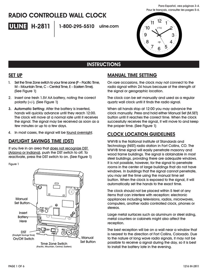
American Time Global Series Instruction Manual
Other American Time Clock manuals
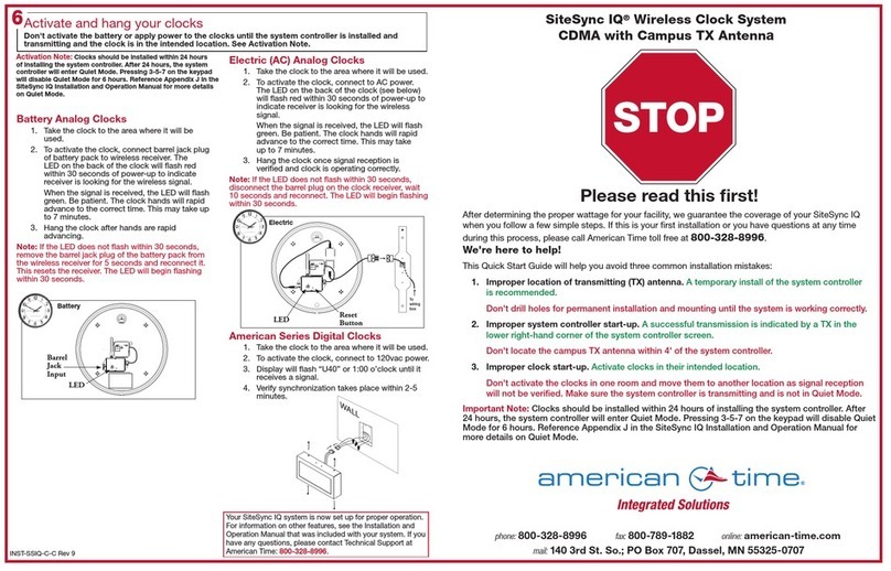
American Time
American Time SiteSync IQ Operating instructions

American Time
American Time H004595 Setup guide

American Time
American Time ALLSYNC IQ MASTER Instruction Manual
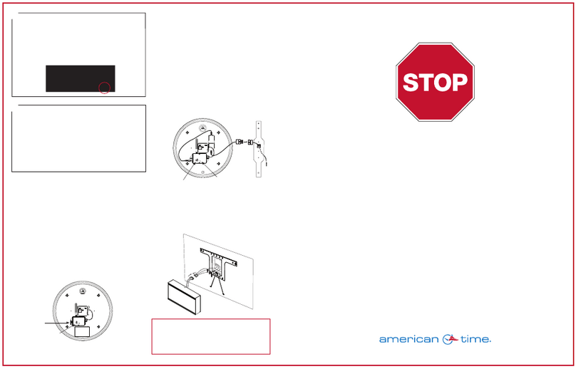
American Time
American Time SiteSync IQ User manual
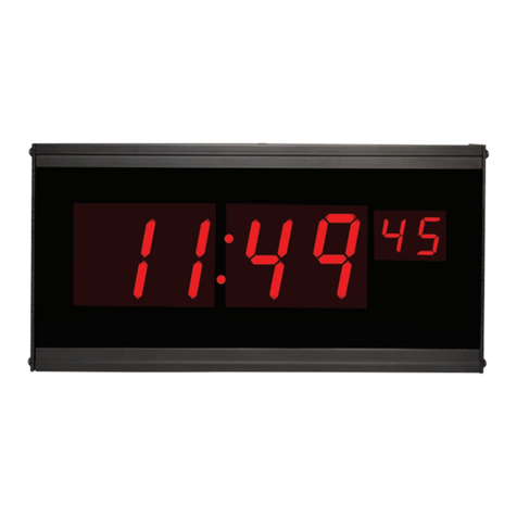
American Time
American Time DSY261RSxE User manual
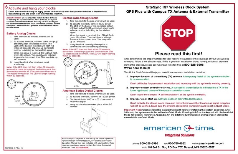
American Time
American Time SiteSync IQ Instruction Manual
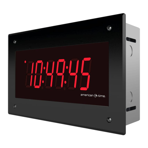
American Time
American Time SSIQ Instruction Manual
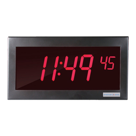
American Time
American Time DSY261RSAE User manual

American Time
American Time SiteSync IQ Instruction Manual
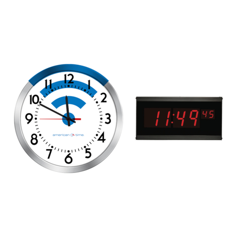
American Time
American Time H004817 User manual
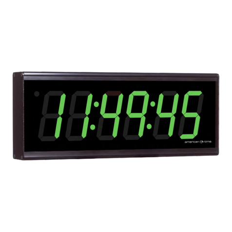
American Time
American Time SiteSynq IQ User manual
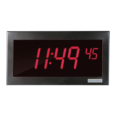
American Time
American Time SQA261RSAEA User manual
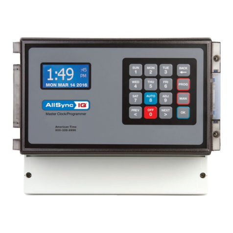
American Time
American Time AllSync IQ ASQMSTR-00X8E User manual

American Time
American Time ALLSYNC IQ Instruction Manual

American Time
American Time Wi-Fi Battery Analog Clock Instruction Manual

American Time
American Time WN261RSxE User manual
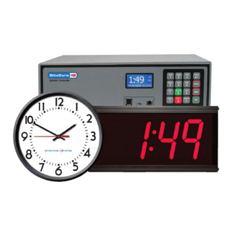
American Time
American Time SiteSync IQ Instruction Manual

American Time
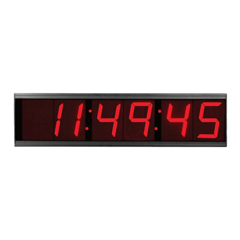
American Time AllSync Plus User manual
American Time
American Time SQA461RSxE User manual

American Time
American Time SiteSync IQ Instruction Manual
Popular Clock manuals by other brands
Sapling
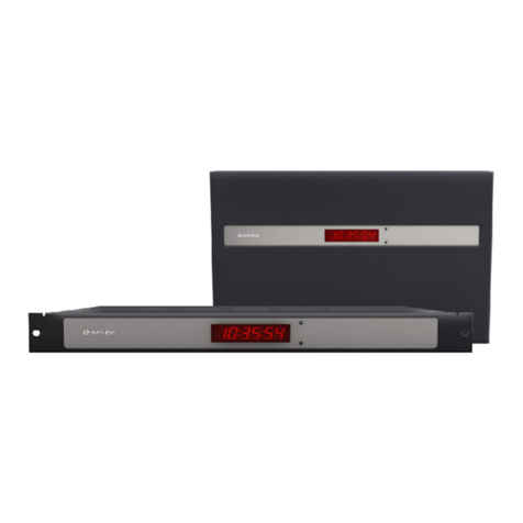
Sapling NTP 7000 Series installation manual
Amano
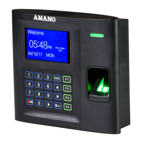
Amano MTX-30F Installation & operation guide

La Crosse Technology
La Crosse Technology BBB86118v3 Setup guide

BEARWARE
BEARWARE 304474 manual
LS & S
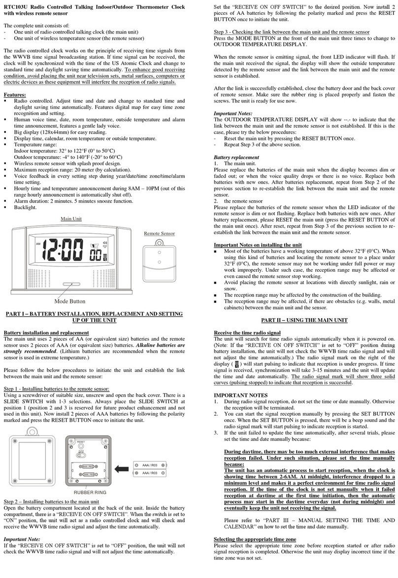
LS & S RTC103U instruction manual
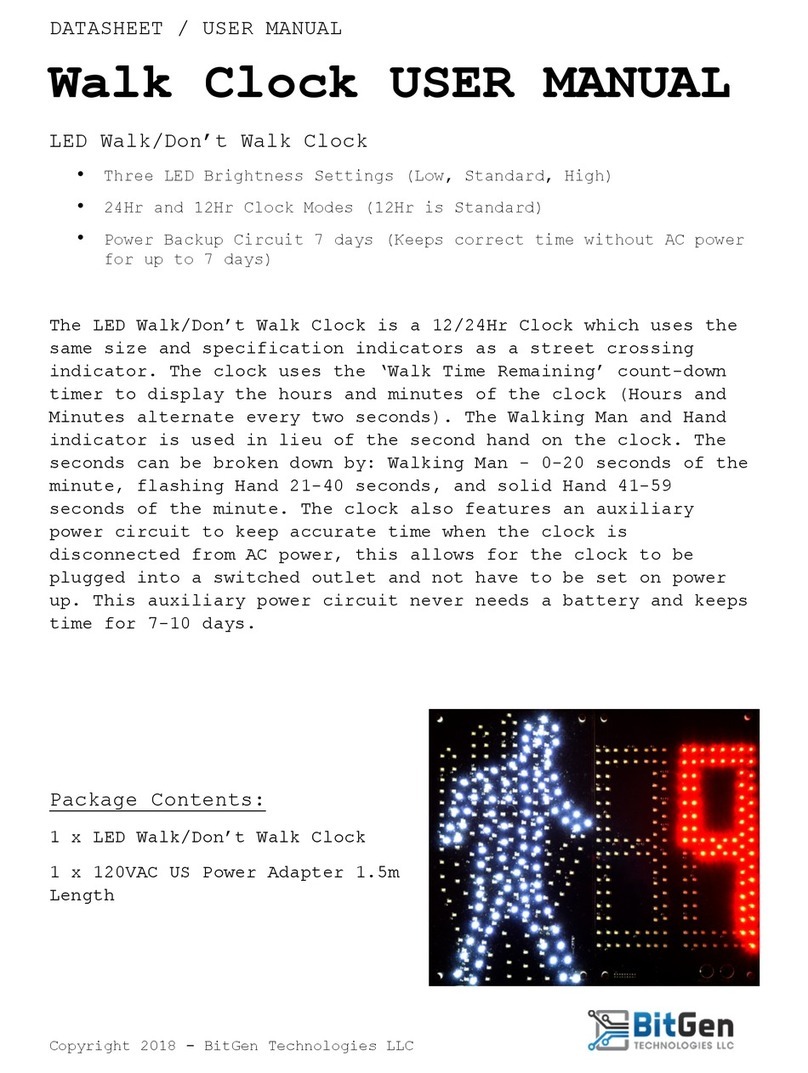
BitGen Technologies
BitGen Technologies LED Walk/Don't Walk Clock user manual

Heathkit
Heathkit GC-1005 Assembly manual

Oregon Scientific
Oregon Scientific PRYSMA RMR221P manual

Andrew O'Malley
Andrew O'Malley DOTKLOK Assembly instructions

Nixie Clock
Nixie Clock Divergence Meter user manual

La Crosse Technology
La Crosse Technology WS-8256-AL user manual

Mini Gadgets
Mini Gadgets MCPro user manual


