Ametek Land ADT User manual

Aluminium Die Thermometer
Copyright © 2003 - 2015 Land Instruments International
User Guide
Issue 4
21 April 2015
Publication No198.65
Language: English

Health and Safety Information
Read all of the instructions in this booklet - including all the WARNINGS and CAUTIONS
- before using this product. If there is any instruction which you do not understand.
DO NOT USE THE PRODUCT.
Safety Signs
WARNING
Indicates a potentially hazardous situation which, if not avoided, could result in death or
personal injury.
CAUTION
Indicates a potentially hazardous situation which, if not avoided, could result in minor or
moderate injury to the user or users, or result in damage to the product or to property.
NOTE
Indicates a potentially hazardous situation which, if not avoided, could result in damage or the loss of
data.
Signs and Symbols used on equipment and Documentation
Caution, risk of electric shock.
Caution, attention to possibility of risk of damage to the product, process or surroundings.
Refer to instruction manual.
Caution, hot surface.
Protective Conductor Terminal.
Observe precautions for handling electrostatic discharge sensitive devices.
Equipment Operation
Use of this instrument in a manner not specied by Land Instruments International may be hazardous.
Read and understand the user documentation supplied before installing and operating the equipment.
The safety of any system incorporating this equipment is the responsibility of the assembler.
Protective Clothing, Face and Eye Protection
It is possible that this equipment is to be installed on, or near to, machinery or equipment operating at
high temperatures and high pressures. Suitable protective clothing, along with face and eye protection
must be worn. Refer to the health and safety guidelines for the machinery/equipment before installing
this product. If in doubt, contact Land Instruments International.
Electrical Power Supply
Before working on the electrical connections, all of the electrical power lines to the equipment must
be isolated. All the electrical cables and signal cables must be connected exactly as indicated in these
operating instructions. If in doubt, contact Land Instruments International.
Storage
The instrument should be stored in its packaging, in a dry sheltered area.
Unpacking
Check all packages for external signs of damage. Check the contents against the packing note.
Lifting Instructions
Where items are too heavy to be lifted manually, use suitably rated lifting equipment. Refer to the
Technical Specication for weights. All lifting should be done as stated in local regulations.
IMPORTANT INFORMATION - PLEASE READ
Contact Us
UK - Droneld
Land Instruments International
Tel: +44 (0) 1246 417691
Email: [email protected]
Web: www.landinst.com
USA - Pittsburgh
AMETEK Land, Inc.
Tel: +1 412 826 4444
Web: www.ametek-land.com
For further details on all LAND/Ametek ofces, distributors and representatives, please visit
our websites.
Return of Damaged Goods
IMPORTANT If any item has been damaged in transit, this should be reported to the carrier and to the
supplier immediately. Damage caused in transit is the responsibility of the carrier not the supplier.
DO NOT RETURN a damaged instrument to the sender as the carrier will not then consider a claim. Save
the packing with the damaged article for inspection by the carrier.
Return of Goods for Repair
If you need to return goods for repair please contact our Customer Service Department. They will be
able to advise you on the correct returns procedure.
Any item returned to Land Instruments International should be adequately packaged to prevent damage
during transit.
You must include a written report of the problem together with your own name and contact information,
address, telephone number, email address etc.
Design and Manufacturing Standards
The Quality Management System of Land Instruments International is approved to BS EN ISO 9001 for
the design, manufacture and on-site servicing of combustion, environmental monitoring and non-contact
temperature measuring instrumentation.
Approvals apply in the USA
This instrument complies with current European directives relating to Electromagnetic
Compatibility 89/336/EEC, Low Voltage Directive 73/23/EEC, and ATEX Directive 94/9/EC.
The Quality Management System of Ametek Motors (Shanghai) Co. Limited is approved to
ISO9001:2008 for the Design and Manufacturing of Motors and the Manufacturing of Gas
Analysers.
Operation of radio transmitters, telephones or other electrical/electronic devices in close
proximity to the equipment while the enclosure doors of the instrument or its peripherals
are open, may cause interference and possible failure where the radiated emissions exceed
the EMC directive.
The protection provided by this product may be invalidated if alterations or additions are made to the
structural, electrical, mechanical or pneumatic parts of this system. Such changes may also invalidate the
standard terms of warranty.
Copyright
This manual is provided as an aid to owners of Land Instruments International’s products and contains
information proprietary to Land Instruments International. This manual may not, in whole or part, be
copied, or reproduced without the expressed written consent of Land Instruments International Ltd.
Copyright © 2014 Land Instruments International.
MARCOM0311

Thermometer User Guide

User Guide Thermometer
Contents
1 Introduction 1
1.1 ADT Thermometer Introduction 1
1.2 About this Guide 1
1.3 About the ADT Thermometer 1
1.4 Unpacking the Thermometer 2
1.5 Nomenclature 3
2 Specications 4
3 Installation 5
3.1 Positioning the Optic Head 6
3.2 Installing the Optic Head 7
3.3 Installing the Lightguide 8
3.4 Positioning the Thermometer 8
3.5 Electrical Connections 9
3.6 Electrical Connections to Landmark Processors 11
4 Optics 12
4.1 Focal Distance 12
4.2 Optic Head A50 - Field of View 75:1 (No Spacer) 12
5Emissivity 13
5.1 Die Emissivity 13
6Maintenance 14
6.1 Optic Head 14
6.2 Air Supply 14

Thermometer User Guide

Page 1
User Guide Thermometer
ADT
1 Introduction
1.1 ADT Thermometer Introduction
The Land ADT (Aluminium Die Thermometer) is used for measuring the
temperature of pre-heated aluminium extrusion dies as they are moved from
the die oven to be installed into the aluminium extrusion press.
1.2 About this Guide
This guide gives the necessary information required to operate Land ADT
thermometer. Basic information regarding installation and mountings and
accessories can be found in the ADT Installation Guide. Where reference is
made to a system processor, further information can be found in the LMG AE
Processor User Guide.
The equipment detailed in this User Guide and any associated Guides should
be used, maintained and serviced by suitably trained personnel, capable of
safely following the procedures and guidelines given in these instructions.
1.3 About the ADT Thermometer
The ADT Thermometer is a highly accurate, non contact thermometer
designed to be used in conjunction with the LMG AE Processor from which it
derives the nominal ±20V d.c. power supply required by its integral
electronic circuits.
The thermometer features include:
• A 3.5m/11.4ft Fibroptic lightguide, enabling the thermometer’s
electronics to be located away from the often hostile measurement
location.
• A 500mm/19.6in optic head focus distance.
• Electrical connections for a 4 to 20mA output, linear over the
temperature span of the thermometer, and an emissivity input for high
accuracy temperature measurement.
• A full range of mountings and accessories for use where the
thermometer is to be installed into hostile environments.

Page 2
Thermometer User Guide
ADT
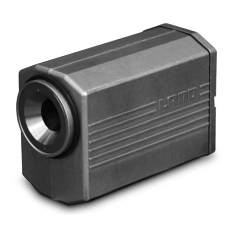
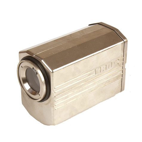
Fig. 1 ADT Aluminium Die Thermometer 265001
1.4 Unpacking the Thermometer
It is important to fully check all equipment with which you have
been supplied.
The packaging should contain the following items:
• ADT Thermometer Installation Guide
• ADT Thermometer User Guide
• A binder for all user documentation
• ADTThermometerttedwithFibropticlightguideandopticheadwith
protective lens cap.
It is recommended that the protective lens cap is kept attached until
thermometer installation is fully complete.

Page 3
User Guide Thermometer
ADT
1.5 Nomenclature
The thermometer detail label is situated on the rear face of the thermometer,
above the lightguide connector. Make a note of the Instrument type and
thermometer serial number from this detail label as this information will be
requiredwhenconguringthethermometertotheLMGAEprocessor.Enter
the information in the spaces below:
Instrument Type:
Serial Number:

Page 4
Thermometer User Guide
ADT
Specification temperature span: 300 to 1100°C/600 to 2000°F
Wavelength: 1.6μm
Response time: 5ms (0 to 95%)
Field of view (nominal): 22:1
Fibroptic lightguide length: 3.5m/11.4ft
Target diameter: A50 head-23mm/0.90in at 500mm/19.6in
Accuracy: Repeatability <1K
Absolute <0.25%K + 1K
Stability: Temperature 0.2°/°ambient
Time 2°C/4°F per year
Vibration: 3G any axis, 10 to 300Hz
Humidity: 0 to 99% non condensing
Sealing: IP65
Ambient temperature:
Optic head
Lightguide
Detector
200°C/392°F
200°C/392°F
Specified 0 to 50°C/32 to 122°F
Operating-10 to 60°C/14 to 140°F
CE: EN 50-082-2 (immunity)
EN 50-081-1 (emissions)
IEC 1010 (electrical safety)
Processor type: LMG AE (LMB is compatible)
I/O card type: System 4 I/O card
2 Specifications

Page 5
User Guide Thermometer
ADT
This section contains similar information to the ADT Installation Guide.
If the thermometer is to be used in conjunction with a protection jacket and
air purge system (recommended for hostile environments), cross-refer to the
Installation Guides provided with those accessories.
3 Installation
Mounting pad - 2 holes 1/4in BSW
7/0.3 deep on 25/1.0 centres
Recommended orientation of
thermometer to prevent the
ingress of water and a build
up of dirt etc. on electrical and
lightguide connectors
All dimensions in mm/in
Approx. 160/6.30 required
for optic head removal
Minimum bend radius
50/1.97
Lightguide length
L35/Q35 = 3500/137.80
114/1.49
80.5/3.17158/6.22
25/0.9825/1.0 54.5/
2.15
M22 x 1.5
thread
18/0.71
Fig. 2 - ADT Thermometer Installation Dimensions 265002

Page 6
Thermometer User Guide
ADT
3.1 Positioning the Optic Head
In many cases, there are few options on location of the optic head, as this is
generally dictated by the particular measurement application. Observe the
following precautions;
1) The thermometer must be positioned such that, at the chosen target
distance,thetargetislargeenoughtocompletelylltheoptichead's
eldofview.Refertothetargetsizetables,Section4.2.The
thermometer'sviewofthetargetareamustnotbeobstructed.
2) Ensurethattheanglebetweentheoptichead'slineofsightandthe
target area is as near to 90° as possible. However, if this is not possible,
a viewing angle of up to 45° is acceptable.
3) If the optic head is located in an atmosphere containing a high
proportion of dust/smoke etc, an air purge must be used in conjunction
with the optic head. This prevents the lens from becoming dirty. Refer to
the Installation Guide supplied with the mounting/purge assembly.
4) The optic head/lightguide temperature must not exceed the maximum
specied.

Page 7
User Guide Thermometer
ADT
3.2 Installing the Optic Head
The optic head can be mounted directly into a threaded hole in a
user-supplied mounting plate, or connected to one of the range of Land
Fibroptic thermometer mountings by means of the Quick Release Fitting, Land
Part Nº 029.591. To mount the optic head into a plate, refer to Fig. 3(a):
1) Unscrew the clamp nut nearest the lens on the optic head.
2) Pass the optic head through a Ø 22.5mm hole in the plate.
3) Re-ttheclampnutontotheoptichead.Tightenthenutsothe
mounting plate is held securely between the two clamp nuts on the
optic head.
M22 x 1.5P thread Clamp nuts each
side of plate
Fig. 3(a) - Mounting the Optic Head into a Plate 265003a
To mount the optic head into Fibroptic thermometer mountings, refer
to Fig. 3(b):
1) Screw the two clamp nuts up as far as they will go on the thread on the
optichead.For'D'typeopticheads,unscrewandremovethetwoclampnuts.
2) Screw the optic head into the Quick Release Fitting.
3) Attachthetting,plustheoptichead,totheLandFibropticthermometer
mounting by means of the twist lock on the Quick Release Fitting.
Fig. 3(b) - Mounting the Optic Head into Fibroptic Thermometer Mountings 265003b
M22 x 1.5P
thread
L
L=80mm for type ‘D’
L=90mm for type’A’
Clampnutsnotttedon
‘D’ type optic heads
ToLandbroptic
thermometer
mountings
Quick-releasetting
M22 x 1.5P thread

Page 8
Thermometer User Guide
ADT
3.3 Installing the Lightguide
Wheninstallingthebreopticslightguide,observethefollowingprecautions;
1) Ensure that the lightguide is not subjected to any tension or undue force.
It is not necessary to attach the lightguide to surrounding structures,
unless, by leaving it hanging, it might vibrate violently or become a
nuisance or hazard.
2) Install the lightguide as if it were a lightweight electrical cable and
protect it if necessary. The minimum bend radius is 50mm.
3.4 Positioning the Thermometer
When choosing a location for the thermometer, observe the following
precautions;
1) If the thermometer is to be installed in a location where the ambient
temperatureisoutsidetherangespeciedforthethermometer,it
must be mounted in a special cooling/heating jacket available from
Land Instruments.
2) If the thermometer is to be used in conjunction with a protection jacket,
refer to the installation guide provided with the jacket.
3) If the thermometer is to be installed in a location where the ambient
temperatureiswithintherangespeciedforthethermometer,itcanbe
mounted using the two tapped holes on the mounting pad. Either hole
can be used for direct tripod mounting.
4) Choose a location for the thermometer which is free from excessive
vibration, contamination and moisture.
5) It is important that, in order to prevent any possibility of water ingress
into the electronics/detector module, the thermometer is mounted in the
orientation shown in Fig. 2.
6) It is recommended that, in order to minimise the build-up of dirt etc. on
the electrical and lightguide connectors, the thermometer is mounted
such that these connectors are on the underside as shown in Fig. 2.

Page 9
User Guide Thermometer
ADT
3.5 Electrical Connections
The electrical connections for the thermometer power supply, emissivity input
and temperature output are made via the 6-way socket on the rear of the
thermometer. See Fig. 4.
Electrical connections to the thermometer must be made through the pre-wired
plug supplied with the thermometer or through the plug housed in the
protective jacket back cap.
To connect either plug type to the thermometer socket, see Fig. 5:
• Align the red marker near the lugs of the plug with the red marker
located above the keyway in the thermometer socket.
• Push the plug into the socket, ensuring that the locking sleeve slides
forwards, locking the plug to the socket.
To disconnect either plug type from the thermometer socket, see Fig. 5:
• Grip the locking sleeve portion of the plug.
• Slide the locking sleeve rearwards to release the locking mechanism and
disconnect the plug from the thermometer socket.
Fig. 4 - Location of 6-way Electrical Connection Socket 265004
Thermometer Rear View
Thermometer ID Label
6-way Electrical
Connection Socket

Page 10
Thermometer User Guide
ADT
Fig. 5 - Connection of a 6-way Plug to the Thermometer Socket 265005
Keyway
Locking Sleeve
Lugs
Red Markers

Page 11
User Guide Thermometer
ADT
3.6 Electrical Connections to Landmark Processors
If the Fibroptic thermometer is to be used in conjunction with a System 4
Landmark Processor, the thermometer derives its power supply, emissivity
input and temperature output from the processor via the 6-way cable. The
cable connection schedule is given in Fig. 6.
Cable Colour Label Function
Yellow
Blue
White
Screen
Red
Black
Green
T
T-
E+
Screen
V
V-
E-
4 to 20mA linear temperature signal drive
4 to 20mA linear temperature signal return
4 to 20mA emissivity signal drive
Screen
24 to 30V d.c. power (positive)
24 to 30V d.c. power (negative)
4 to 20mA emissivity signal return
Note:-
Two different variants of plug may be encountered - Type A or Type B
Type A Black
Green
White
Red
Yellow
Blue
Black
Green
White
Blue
Yellow
Red
1
2
3
4
5
6
White line
Screen is connected to shell of connector at
thermometer end of cable and pin 4 of
processor connector.
View from solder bucket
side of 6-way connectors
Type B
Fig. 6 Cable Connection Schedule 265006

Page 12
Thermometer User Guide
ADT
4 Optics
4.1 Focal Distance
ADTthermometersutilisean‘A’typeoptichead(nospacertted).
The focal distance of this type of optic head is 00mm / 19.6in.
4.2 Optic Head A50 - Field of View 22:1 (No Spacer)
10.3mm
0.41in
Target Diameter
Target Distance
0mm
0in
12.8mm
0.50in
100mm
3.94in
15.4mm
0.61in
200mm
7.87in
17.9mm
0.70in
300mm
11.81in
20.5mm
0.81in
400mm
15.75in
23.0mm
0.91in
500mm
19.69in
26.1mm
1.03in
600mm
23.62in
265006

Page 13
User Guide Thermometer
ADT
5 Emissivity
In order to obtain accurate temperature measurements, the emissivity value
of the target surface must be known.
If you have a query regarding the emissivity of the target in your
measurement application, contact Land Instruments International for advice.
5.1 Die Emissivity
The ADT Thermometer is a designated instrument, used primarily on
aluminium extrusion die applications. The emissivity of the target area can be
pre-determined and is given as below:
Iron & Steel Dies (unoxidised) 0.30
Iron & Steel Dies (oxidised) 0.85

Page 14
Thermometer User Guide
ADT
6 Maintenance
6.1 Optic Head
After initial installation, make regular inspections of the lens in order to
establish a cleaning cycle.
If the lens requires cleaning, it is preferable to do so without disconnecting
the lightguide from the optic head.
Cleanthelenswithasoftclothandaproprietarycleaninguid.Takecarenot
to scratch or mark the lens.
6.2 Air Supply
If an air purge system is utilised to keep the Fibroptic Thermometer lens free
fromcontamination,theairlterofthisairpurgesystemmustbechecked
atregularintervals.Thecontaminationrateoftheairlterdependson
the quality of the air supplied to the system. Therefore it is essential that
this purge air supply is kept as clean as possible, free from oil or any other
contamination.
Table of contents
Other Ametek Land Thermometer manuals

Ametek Land
Ametek Land LANCOM 4 User manual

Ametek Land
Ametek Land UNO Series User manual

Ametek Land
Ametek Land IQ Series User manual

Ametek Land
Ametek Land CDA User manual

Ametek Land
Ametek Land RT8B User manual

Ametek Land
Ametek Land UNO U1 600/1600C-L User manual

Ametek Land
Ametek Land FLT5A User manual
Popular Thermometer manuals by other brands

Safety 1st
Safety 1st Accu-Touch 49529 user guide

Omron
Omron GentleTemp 510 Gebrauchsanweisung

Citizen
Citizen CT561C operation instruction

Healthwear Technologies
Healthwear Technologies TS101 user manual

Radiant Innovation
Radiant Innovation TH809 operating instructions

Microlife
Microlife MT 60 quick start guide