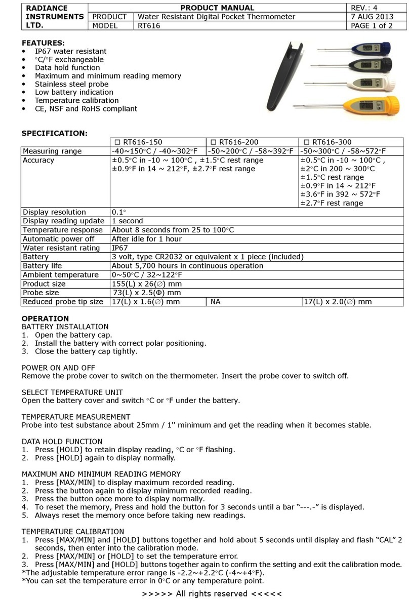
Ametek Land CDA User manual

Incinerator Thermometer
User Guide
Issue 5
04 January 2017
Publication Nº 800682
Language: English
CDA
Copyright © 2002 - 2017 Land Instruments International

Health and Safety Information
Read all of the instructions in this booklet - including all the WARNINGS and CAUTIONS
- before using this product. If there is any instruction which you do not understand, DO
NOT USE THE PRODUCT.
Safety Signs
WARNING
Indicates a potentially hazardous situation which, if not avoided, could result in death or
personal injury.
CAUTION
Indicates a potentially hazardous situation which, if not avoided, could result in minor or
moderate injury to the user or users, or result in damage to the product or to property.
NOTE
Indicates a potentially hazardous situation which, if not avoided, could result in damage or the loss of
data.
Signs and Symbols used on equipment and Documentation
Caution, risk of electric shock.
Caution, attention to possibility of risk of damage to the product, process or surroundings. Refer
to instruction manual.
Caution, hot surface.
Protective Conductor Terminal.
Observe precautions for handling electrostatic discharge sensitive devices.
Equipment Operation
Use of this instrument in a manner not specied by Land Instruments International may be hazardous.
Read and understand the user documentation supplied before installing and operating the equipment.
The safety of any system incorporating this equipment is the responsibility of the assembler.
Protective Clothing, Face and Eye Protection
It is possible that this equipment is to be installed on, or near to, machinery or equipment operating at
high temperatures and high pressures. Suitable protective clothing, along with face and eye protection
must be worn. Refer to the health and safety guidelines for the machinery/equipment before installing
this product. If in doubt, contact Land Instruments International.
Electrical Power Supply
Before working on the electrical connections, all of the electrical power lines to the equipment must
be isolated. All the electrical cables and signal cables must be connected exactly as indicated in these
operating instructions. If in doubt, contact Land Instruments International.
Storage
The instrument should be stored in its packaging, in a dry sheltered area.
Unpacking
Check all packages for external signs of damage. Check the contents against the packing note.
Lifting Instructions
Where items are too heavy to be lifted manually, use suitably rated lifting equipment. Refer to the
Technical Specication for weights. All lifting should be done as stated in local regulations.
IMPORTANT INFORMATION - PLEASE READ
Contact Us
UK - Droneld
Land Instruments International
Tel: +44 (0) 1246 417691
Email: [email protected]
Web: www.landinst.com
USA - Pittsburgh
AMETEK Land, Inc.
Tel: +1 412 826 4444
Web: www.ametek-land.com
China
AMETEK Land China Service
Tel: +86 21 5868 5111 ext 122
Email: [email protected]
Web: www.landinst.com
India
AMETEK Land India Service
Tel: +91 - 80 67823240
Email: [email protected]
Web: www.landinst.com
For further details on all AMETEK Land oces, distributors and representatives, please visit
our websites.
Return of Damaged Goods
IMPORTANT If any item has been damaged in transit, this should be reported to the carrier and to the
supplier immediately. Damage caused in transit is the responsibility of the carrier not the supplier.
DO NOT RETURN a damaged instrument to the sender as the carrier will not then consider a claim. Save
the packing with the damaged article for inspection by the carrier.
Return of Goods for Repair
If you need to return goods for repair please contact our Customer Service Department. They will be able
to advise you on the correct returns procedure.
Any item returned to Land Instruments International should be adequately packaged to prevent damage
during transit.
You must include a written report of the problem together with your own name and contact information,
address, telephone number, email address etc.
Design and Manufacturing Standards
The Quality Management System of Land Instruments International is approved to BS EN ISO 9001 for
the design, manufacture and on-site servicing of combustion, environmental monitoring and non-contact
temperature measuring instrumentation.
Approvals apply in the USA
Operation of radio transmitters, telephones or other electrical/electronic devices in close proximity
to the equipment while the enclosure doors of the instrument or its peripherals are open, may cause
interference and possible failure where the radiated emissions exceed the EMC directive.
The protection provided by this product may be invalidated if alterations or additions are made to the
structural, electrical, mechanical or pneumatic parts of this system. Such changes may also invalidate the
standard terms of warranty.
Copyright
This manual is provided as an aid to owners of Land Instruments International’s products and contains
information proprietary to Land Instruments International. This manual may not, in whole or part, be
copied, or reproduced without the expressed written consent of Land Instruments International Ltd.
Copyright © 2016 Land Instruments International.
MARCOM0311, Issue 7, 01 November 2016
Approvals apply in India
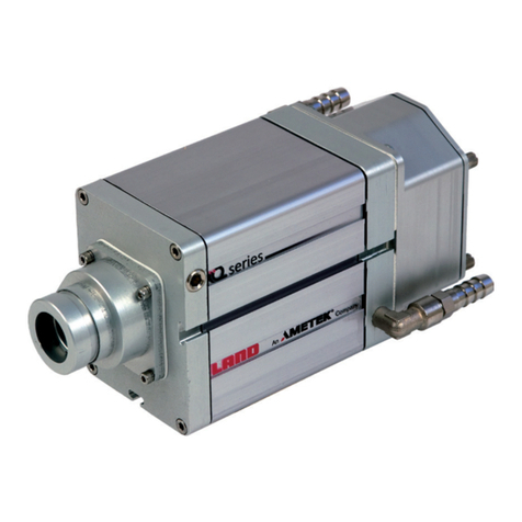
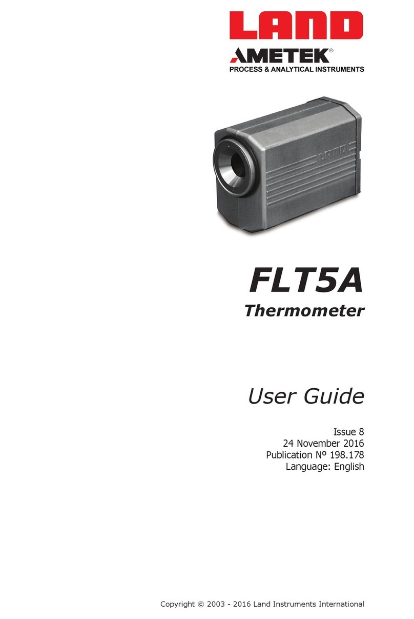
Thermometer User Guide
CDA

User Guide Thermometer
CDA
Contents
1 Introduction 1
1.1 General Introduction 1
1.2 About the CDA
Incinerator Thermometer 1
1.3 Application 2
2 Specications 4
3 Installing the Thermometer 5
3.1 Introduction 5
3.2 Aiming Consideration 5
4 Using the Thermometer 8
4.1 Location of Controls 8
4.2 Adjusting the ‘Emissivity’ Value 9
4.3 Adjusting the Averager ‘Response Time’ 10
4.4 Noting ‘Emissivity’ and ‘Response Time’ Settings 11
5 Electrical Connections 12
5.1 Thermometer Operation 12
5.2 Electrical connections 13
5.3 Loop Resistance 14
6 Mounting and Accessories 15
6.1 Recommendations 15
6.2 Sighting Tubes 15
7 Maintenance 16

Thermometer User Guide
CDA

Page 1
User Guide Thermometer
CDA
1 Introduction
1.1 General Introduction
This publication provides the information required to safely and correctly
operate the LAND CDA Incinerator Thermometer.
The equipment must only be used, maintained and serviced by suitably
trained personnel, capable of carefully following the procedures and guidelines
given in this User Guide and associated publications. Detailed information
regarding installation is contained within the LAND CDA Incinerator
Thermometer Installation Guide.
All User Guides, Installation Guides and Instruction Leaets supplied, should
be read thoroughly before proceeding with any operations detailed
within them.
1.2 About the CDA
Incinerator Thermometer
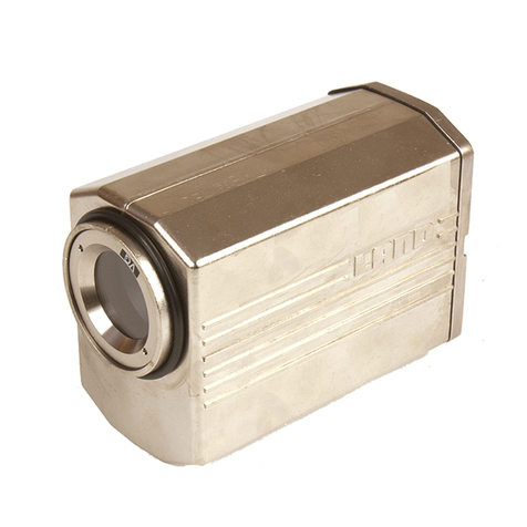
The LAND CDA Incinerator Thermometer is a highly accurate, non contact
thermometer designed for independent or “STAND ALONE” use.
Thermometer features include:
• Stand Alone operation
• Adjustable response speed
• 4 to 20mA loop powered output, linear over the temperature span of
the thermometer
• Built in Emissivity controls
Fig. 1 - Land CDA Incinerator Thermometer 294001

Page 2
Thermometer User Guide
CDA
1.3 Application
The LAND CDA Incinerator Thermometer is designed for taking
measurements of the atmospheric temperature within waste incinerators.
It can be used for gas or ame temperature measurement in a variety of
plant applications, provided that there is sufcient CO2 concentration at
a high temperature and an effective measurement sight path depth. The
measurement is unaffected by a cold CO2 atmosphere, therefore it “sees
through” cold combustion atmospheres, measuring any hot atmosphere
beyond.
In a typical incinerator application, the CDA is mounted externally onto the
incinerator wall, positioned approximately 2 metres above the bed. It is xed
to a protective anged sight tube which penetrates through the incinerator
wall. The thermometer sight path acts as an “invisible thermocouple”,
extending into the incinerator atmosphere (penetration depth depends upon
atmosphere conditions), where atmospheric temperature measurements
are taken.
The CDA thermometer is fully protected from the harsh environments
encountered in incinerator applications by utilising the Land protective jacket
assembly which is air or water-cooled and an air-purged sighting tube.
Fig. 2 - CDA Thermometer in Protective Jacket Assembly 294002
Position of CDA
Thermometer Within
Jacket Assembly
Sighting Tube
Mounting Flange Air Purge Protective Jacket
Assembly
Air/Water Cooling
Back Cap
Electrical
Connections

Page 3
User Guide Thermometer
CDA
Fig. 3 - Thermometer Sighting diagram 294003
Fig. 4 - Thermometer Protective Jacket Assembly dimensions 294004
600mm/23.6in
Parallel FOV
20mm/0.79in
Lens
Diverging FOV
Thermometer removal clearance
Approx. 200/8.0
Side View
150/5.9 170/6.7 110/4.4
117/4.6
Top View
120/4.7
430/17.0
All dimensions in mm/in Not to scale
3x equi-spaced mounting
holes 6.5 to 7.0/0.26 to 0.28
clearance for M6 bolts

Page 4
Thermometer User Guide
CDA
Temperature Range 400 to 1800°C/752 to 3272°F
Output: 4 to 20mA linear (2-wire loop connection)
Must not be isolated to >50V from earth
Field of View: 20mm/0.79in parallel
to 600mm/23.6in (nominal)
Alignment: Permissible misalignment between thermometer
optical and mechanical axes = 1°
Emissivity: 0.10 to 1.00 in 0.01 increments
Response Time (3t): 1 to 10s (adjustable)
Resolution: <0.5°C/1°F
Accuracy:
(absolute)
<0.5% Kelvin over 600 to 1600°C/1112 to 2912°F
<1% Kelvin over 400 to 600°C/752 to 1112°F
<1% Kelvin 1600 to 1800°C/2912 to 3292°F
Drift with ambient temperature: <2° per 10° ambient
Drift with Time: <1°C/2°F per year
Environmental Specication
Ambient Temperature Limits:
Humidity:
Sealing:
CE:
Vibration:
Power Supply:
5 to 50°C/41 to 122°F
0 to 99% non-condensing
To IP65/NEMA4X requirements
EN 50-082-2 (immunity)
EN 50-081-1 (emission)
IEC 1010 (safety)
3g - 10 to 300Hz
11 to 45V d.c.
2 Specifications

Page 5
User Guide Thermometer
CDA
3.1 Introduction
The information detailed within this section of the CDA User Guide, should be
cross-referred with information found in the CDA Installation Guide.
If the thermometer is to be used in conjunction with a protection jacket and
air purge (recommended), refer to the Installation Guides supplied with the
relevant accessory.
3.2 Aiming Consideration
The thermometer senses radiation (only) from within a well dened
eld-of-view. Fig. 3 shows this. The thermometer will normally be sighted
down a tube which penetrates the incinerator wall. This tube must not “clip”
the eld of view and thus needs to be of sufcient diameter. Fig. 6 shows
recommended minimum internal diameter versus tube length - reasonable
allowance is included here for misalignments.
The instrument responds to hot CO2 in the atmosphere. To obtain an accurate
reading there must be a sufcient “column depth” of CO2 - i.e. enough path
length at a high enough concentration. The column depth actually required
depends on the temperature. As a “rule of thumb” good measurements are
possible for temperatures above 600°C where the concentration exceeds 4%
in a path length of several metres. A more precise indication is given in Figs.
7 and 8. These errors assume a cold back wall and will be reduced if the back
wall temperature is close to the gas temperature. They add to the “black
body” errors in the instrument specication above.
3 Installing the Thermometer
Sighting Tube Furnace Bed
Fig. 5 - Thermometer aimed above furnace bed 294005

Page 6
Thermometer User Guide
CDA
Fig. 7 - Thermometer error at 1500K gas temperature 294007
Fig. 6 - Minimum recommended Sight Tube diameters 294006
70
60
50
40
30
20
10
0
0 100 200 300 400 500 600 700 800
Sight tube length (mm)
Minimum internal diameter (mm)
Path length (metres)
Error (°C)
0
-50
-100
-150
-200
8 7 6 5 4 3 2
8% CO2
6% CO2
4% CO2
2% CO2
Thermometer error versus path length for several CO2
concentrations. Gas temperature 1500K

Page 7
User Guide Thermometer
CDA
Fig. 8 - Thermometer error at 1200K gas temperature 294008
Path length (metres)
Error (°C)
0
-50
-100
-150
-200
8 7 6 5 4 3 2
8% CO2
6% CO2
4% CO2
2% CO2
Thermometer error versus path length for several CO2
concentrations. Gas temperature 1200K

Page 8
Thermometer User Guide
CDA
4 Using the Thermometer
It is recommended that the ‘Emissivity’ and ‘Response Time’ controls are set
to match the requirements of the particular measurement location before
installation. This is particularly relevant if the thermometer is to be used in a
location which is difcult to access and/or used in conjunction with a jacket
and back cap.
4.1 Location of Controls
The ‘Emissivity’ and ‘Response Time’ control switches are located on the rear
face of the thermometer. The controls are protected by a screw-on cap
(See Fig. 9).
NOTE
To keep the thermometer electronics sealed against ingress of dust and
moisture, always replace the screw-on cap after adjusting the settings.
Fig. 9 - Location of the screw-on cap 294009
Screw-on cap

Page 9
User Guide Thermometer
CDA
4.2 Adjusting the Emissivity value
For accurate temperature measurement, the Emissivity setting must be set
to correspond with the target being measured.
The emissivity can be set in the range 0.10 to 1.00 in steps of 0.01.
The CDA is supplied with the emissivity factory-set to 1.00.
The Emissivity value is set using switches SW1 and SW2. See Fig. 10.
When switch SW1 is set from 1 to 9, this denotes the rst gure after the
decimal point of the emissivity value.
e.g. for an emissivity value of ‘0.85’, set SW1 to ‘8’ and SW2 to ‘5’.
When switch SW1 is set to 0, this denotes a ‘1’ before and a ‘0’ after, the
decimal point of the emissivity value.
e.g. for an emissivity value of ‘1.00’, set SW1 to ‘0’ and SW2 to ‘0’.
NOTE
For an opaque gas measurement, an emissivity value of 1.00 should be
used.
Fig. 10 - ‘Emissivity’ and ‘Response Time’ controls 294010
Emissivity
Example = 0.85
Response time (3t)
Fully anti-clockwise = 1 sec
Fully clockwise = 10 sec
SW2
SW1
P1
Example settings
Emissivity SW1 SW2
0.10 1 0
0.80 8 0
0.85 8 5
0.92 9 2
1.00 0 0
e
=0.85

Page 10
Thermometer User Guide
CDA
4.3 Adjusting the Averager Response Time
The response time control allows the time constant of the thermometer to be
adjusted to suit the application.
NOTE
For longer time constants (e.g. to mimic thermocouples), an averaging
meter is advised. Suitable units provide 0 to 999 seconds of response, 4
to 20 mA retransmission output and also power to the CDA.
For further information, contact Land Instruments International.
To adjust the Averager Response Time function, use the potentiometer P1
(see Fig. 10). The Response Time value can be set to between 1 and 10
seconds (for 0 to 95% of the nal reading).
For a faster Response Time:
Turn the potentiometer P1 anticlockwise. If P1 is turned fully
anticlockwise, the ‘Response Time’ is at the fastest setting (approx. 1
second).
For a slower Response Time:
Turn the potentiometer P1 clockwise. If P1 is turned fully clockwise, the
‘Response Time’ is at the slowest setting (approx. 10 seconds).

Page 11
User Guide Thermometer
CDA
4.4 Noting ‘Emissivity’ and ‘Response Time’ Settings
It is advisable to make a note of the settings for ‘Emissivity’ and ‘Response
Time’, once these settings have been determined and veried. Each time a
re-adjustment is made to the settings, make a note in the table below, using
the spaces provided. This table can then be used as a quick reference guide.
CDA
Serial Number Date Emissivity Response Time

Page 12
Thermometer User Guide
CDA
5 Electrical Connections
5.1 Thermometer Operation
The LAND Incinerator Thermometer is a rugged, stand alone, non contact
thermometer, designed for measuring relatively low temperatures in hostile
environments. It has a temperature measurement range of 400 to
1800°C/752 to 3272°F.
The thermometer operates on a simple 4 to 20mA current loop. A block
diagram of the key features of the thermometer is shown in Fig. 11.
The thermometer is contains an integral lens, which focuses infrared radiation
from a predened target area onto an infrared detector. This detector
converts the incoming infrared radiation into a low level electrical voltage
which is proportional to the temperature of the target. This electrical voltage
is then amplied, corrected for emissivity and linearized to produce an analog
4 to 20mA current output.
Fig. 11 - Thermometer block diagram 294011
Incoming
infrared
radiation
from
target spot
Lens Infrared
detector
Amplier
Lineariser
Emissivity
Speed of
Response
4 to 20mA
Driver
Current
loop
In normal operation the 4-20mA output is designed to stay within the
‘saturation’ range as dened by NAMUR NE43.
Fail High - >= 21.0mA
Saturation High - 20.5mA
Signal Range - 4-20mA
Saturation Low - 3.8mA
Fail Low - <= 3.6mA

Page 13
User Guide Thermometer
CDA
5.2 Electrical connections
The electrical connections for the thermometer power supply and temperature
outputs are made via the 6-way socket on the rear of the thermometer.
The 6-way cable connections are as follows:
Thermometer Pin Function Cable Colour End Cap Pin No.
1
2
3 V+, 4 to 20mA Red 5
4
5
6 V-, 4 to 20mA Black 6
Electrical connections to the CDA thermometer must be made through the
prewired plug supplied with the thermometer or through the plug housed in
the protective jacket back cap.
To connect either plug type to the thermometer socket:
• Align the red marker near the lugs of the plug with the red marker
located above the keyway in the thermometer socket.
• Push the plug into the socket, ensuring that the locking sleeve slides
forwards, locking the plug to the socket.
To disconnect either plug type from the thermometer socket:
• Grip the locking sleeve portion of the plug.
• Slide the locking sleeve rearwards to release the locking mechanism and
disconnect the plug from the thermometer socket.
Fig. 12 - Connection of a 6-way plug to the thermometer socket 294012
Locking Sleeve
Keyway
Red Markers
Lugs

Page 14
Thermometer User Guide
CDA
5.3 Loop Resistance
The maximum allowable resistance in the thermometer current loop for a
givenpower supply voltage is illustrated in Fig. 13. Information on how to
adjust thepower supply voltage for a LAND power supply is given in the Power
Supply Unit User Guide.
Fig. 13 - Graph showing load resistance versus power supply voltage 294013
NOTE
The system load resistance includes the cable resistance and the indicator
resistance.
Power Supply Voltage (V)
Maximum Loop Resistance (ohms)
1000
900
800
700
600
500
400
300
200
100
0
0 5 10 15 20 25 30 35
Table of contents
Other Ametek Land Thermometer manuals

Ametek Land
Ametek Land LANCOM 4 User manual

Ametek Land
Ametek Land UNO Series User manual

Ametek Land
Ametek Land FLT5A User manual

Ametek Land
Ametek Land UNO U1 600/1600C-L User manual

Ametek Land
Ametek Land ADT User manual

Ametek Land
Ametek Land IQ Series User manual

Ametek Land
Ametek Land RT8B User manual