AMI 111B User manual

AMI
Oxygen Analyzer Manual
Model 111B
AMI, Costa Mesa, CA

AMI Analyzer Manual Contents i
Contents
Preface 1
The AMI story 1
Caution 1
Address 1
Model 111B Oxygen Analyzer 2
Introduction 2
Features: 2
Data logging: 2
Pump: 3
Safety: 3
Sensor Warranty: 3
Instrument Warranty: 3
Installation and Operation 4
Receiving the analyzer 4
Charge the batteries: 4
Location: 4
Sample gas and electrical connections : 5
Interconnections: 6
Digital communications: 6
Sample connection: 6
Operation 7
General Description: 7
Front Panel Controls: 7
Flow Rate Adjustment: 7
Front panel LED: 7
Calibration 8
Logging: 9
Retrieving Logged Data: 9

AMI Analyzer Manual Contents ii
Maintenance and troubleshooting 10
Maintenance: 10
Sensor Replacement: 10
Battery Replacement: 10
Troubleshooting 11
All oxygen applications 11
Specifications and Disclaimer 13
Specifications: 13
Disclaimer 14
Index 15

AMI Analyzer Manual Preface 1
Preface
The AMI story
The AMI series of analyzers provide the latest in high-definition oxygen analysis. The series includes trace oxygen,
percent oxygen and portable trace and percent oxygen models. All of them share the same basic design approach, using
time proven oxygen sensors and advanced high definition electronics for noise and interference free performance.
AMI was formed by a group of analyzer professionals with over forty years of experience between them. The company is
dedicated to providing the very best and most cost effective solutions to the oxygen analysis problem with a range of
analyzers.
Every effort is made to ensure that AMI products provide reliable, effective performance. However there are many
pitfalls in achieving correct oxygen analysis, particularly at low ppm levels, and AMI stands ready to provide a complete
solution to the analysis problem, from sample system design to on-site troubleshooting and problem analysis. Please feel
free to call AMI for help should your results not meet your expectations.
Caution
Read and understand this manual fully before attempting to use the instrument. In particular understand the hazards
associated with using flammable or poisonous gases.
Address
Advanced Micro Instruments.
225 Paularino Ave
Costa Mesa, CA 92626
(714) 848-5533
www.amio2.com
Last Revised: 08/31/2018

AMI Analyzer Manual Model 111B Oxygen Analyzer 2
Model 111B Oxygen Analyzer
Introduction
The Advanced Micro Instrument Model 111B provides the latest in high precision oxygen measurement. The Model
111B incorporates a state of the art Zirconium Oxide sensor that provides unprecedented accuracy and stability, while
retaining the traditional AMI features and ease of use.
Features:
Compact size
Portable
Battery powered
Auto-ranging display
Data logging function
Air calibration, no zero gas required
Extreme stability
High accuracy and fast response
Large liquid crystal display
12VDC 110/240V charger supplied.
Built-in pump
Built-in flame arrestors
Backed by a two year warranty
Data logging:
The unit contains a real-time clock and 32K of non-volatile ferro-electric memory that provide a data logging function. It
will automatically log readings and the time and date at intervals for subsequent downloading into a computer.
It records the average reading over a user-selectable period (in minutes), and occasionally it records the time and date so
that the user may reconstruct the data accurately. If logging is turned off, and then restarted, it will continue logging
where it left off (starting with a new time and date stamp) –it won’t overwrite the earlier data until it reaches the end of
its memory.
Using the computer program supplied if desired by AMI, the data may be downloaded into a “CSV” file for manipulation
in Excel™ or similar spreadsheet programs, and the logging can be restarted at the beginning again. The internal time
and clock may also be set, as well as a label to distinguish data from this analyzer from others.

AMI Analyzer Manual Model 111B Oxygen Analyzer 3
If the time interval is set for 1 minute, the unit will average the readings for one minute and then store the average. Every
32 minutes it will also store the current date and time. It will continue doing this for about 20,000 data points, i.e. about
two weeks, assuming it is left plugged in to its charger! After that time it will start writing over its earliest data.
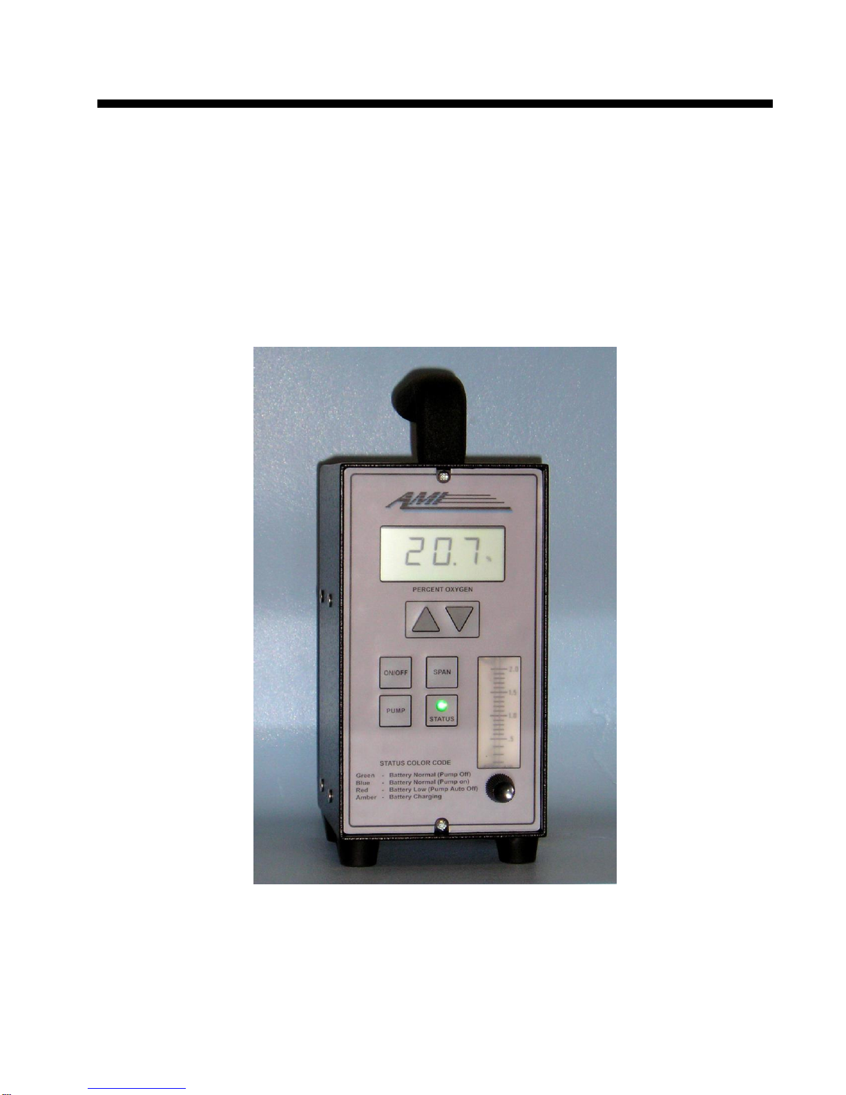
Pump:
The model 111B is equipped with a long-life pump, capable of drawing a sample through the sensor from an ambient
pressure source. It draws a lot of current, and so it is only suitable for spot checking. The unit will switch off the pump
after a few minutes of operation. The LED on the front panel will change from green to blue when the pump is in use.
Note that the pump will not run while the batteries are being charged. If the batteries are low, the pump will only run for
five seconds. Sometimes when the batteries are getting low, the increased current draw of the pump will reduce the
battery voltage and thus turn the pump off –in this case both the red and blue LED’s will come on while the pump is
running.
Safety:
The unit is equipped with two flame arrestors, on the inlet and outlet of the sample passage to the sensor. Under no
circumstances remove these! They will prevent the sensor from igniting any flammable sample or atmosphere. The unit
is designed to meet the requirements for a division II area classification: this means that you should NOT use it if you
KNOW that you are in an explosive atmosphere, but you can use it if there is a possibility that the atmosphere might
become so. In other words, if you are standing in a puddle of jet fuel don’t use it! It won’t cause an explosion even if
you do as long as nothing goes catastrophically wrong with the unit while you are standing there, but please don’t take the
risk. You can use it if you are in an area where someone might spill jet fuel but hasn’t actually done so yet.
You should not use it with samples that actually contain a flammable gas, even though the flame arrestors will stop a
flame from propagating out of the analyzer.
Oxygen sensor:
The Model 111B’s Zirconium oxide sensor produces an output current in proportion to the amount of oxygen present,
and has virtually zero output in the absence of oxygen, thus avoiding any requirement to zero the analyzer. The span
calibration may be performed using a standard span gases or compressed ambient air. The sensor is so stable that span
calibrations are only necessary once or twice a year.
WARNING
All zirconium oxide sensors operate at high temperature, and are unsuitable for measuring
flammable gases. Any hydrocarbon gas will oxidize on the sensor, reducing the oxygen reading by
the amount of oxygen required to burn the hydrocarbons. DO NOT USE THIS ANALYZER
WITH FLAMMABLE OR EXPLOSIVE SAMPLES!
Sensor Warranty:
The sensor is warranted to operate for at least two years, with an expected life between five and ten years.
Instrument Warranty:
Any failure of material or workmanship will be repaired free of charge for a period of two years from the original
purchase (shipping date) of the instrument. AMI will also pay for one way shipment (back to the user).
Any indication of abuse or tampering will void the warranty.

AMI Analyzer Manual Installation and Operation 4
Installation and Operation
Receiving the analyzer
When you receive the instrument, check the package for evidence of damage and if any is found, please contact the
shipper.
Charge the batteries:
Plug the wall adapter supplied into a suitable wall socket. The charger is a universal charger, and can be plugged into
any voltage between 100 and 240 VAC. Plug the power jack into the back of the analyzer, and allow it to sit overnight
for at least 14 hours. The internal charging circuit will not allow the batteries to be overcharged. The batteries will last
for about 8 hours of continuous operation if you don’t use the pump; the pump will drain them in about an hour if you use
it continuously. The circuitry won’t allow the pump to run while the unit is recharging (otherwise the batteries would
never get charged!)
Location:
The unit is designed to be used in a general-purpose or class 1 division 2 group CD area. It is not suitable for use in a
class 1 division 1 area. It may be operated either off its internal batteries or else off the charger, in which case it will
simultaneously operate (except for the pump) and recharge itself.
Although the unit is RFI protected, do not to mount it close to sources of electrical interference such as large
transformers, motor start contactors, relays etc. Also avoid subjecting it to significant vibration.

AMI Analyzer Manual Installation and Operation 5
Figure 1. Outline Drawing
Sample gas and electrical connections :
The sensor is built into the analyzer, and does not need any separate installation. It is equipped with a standard
Swagelokfitting that is suitable for use with a hose designed to mate with the fitting on an aircraft. This hose must be
separately procured and musat be selected according to the aircraft fitting used.
The exhaust should be left open. UNDER NO CIRCUMSTANCES REMOVE THE EXHAUST FITTING! It is a
flame arrestor, and removing it will turn the analyzer into a guaranteed ignition source.

AMI Analyzer Manual Installation and Operation 6
The only electrical connection, other than the charger input, is a USB connector suitable for use with an AMI supplied
cable.
The unit is powered by its internal batteries but may also be powered as well as recharged by plugging in the power
adapter supplied to the socket on the rear of the unit (except that the pump will not operate).
Interconnections:
Digital communications:
The Model 111B is equipped with a special USB connector on the back of its case. This may be used to access data that
has been logged by the built-in data logger.
Use a cable and software supplied by AMI to configure and download data.
Sample connection:
This unit is designed to be used with a hose provided by the user. It is important that the hose used has appropriate
fittings on each end –the end attached to the analyzer may be a simple ¼” tube, or an O-ring type fitting designed to mate
with the Swagelokfittings supplied. If the aircraft supply is under positive pressure, adjust the flow with the flowmeter
valve to 1 SCFH: if the aircraft is not at positive pressure, turn on the pump with the “Pump” button, and again adjust the
flow to 1 SCFH. Allow the reading to stabilize, and take the reading. As soon as you are satisfied, turn the pump back
off (or let it turn itself off after five minutes) so as to minimize battery consumption.
IT IS IMPORTANT THAT THE READING IS ALWAYS TAKEN AT 1SCFH FLOW RATE –THE SAME 1
SCFH FLOW RATE THE UNIT IS CALIBRATED TO. The flame arrestors by their nature provide some flow
restriction, so that the pressure seen by the measurement cell will increase as the flow rate increases, increasing the
measured oxygen in proportion.

AMI Analyzer Manual Installation and Operation 7
Operation
General Description:
This analyzer is designed to be as simple to operate as possible. The analyzer displays the oxygen level in appropriate
units on the LCD, automatically adjusting its sensitivity as required. Please note that the sensor takes about two
minutes to warm up when the analyzer is turned on. During this time, the analyzer will at first display 0% oxygen,
and then the reading will climb up and overshoot before settling back down. Don’t span it for at least ten minutes after it
has warmed up as its reading may change by 0.1% oxygen over that time. You can adjust the sample flow rate with the
needle valve on the front of the analyzer and see what it is on the built-in flowmeter.
Front Panel Controls:
The basic operation of the analyzer is controlled from its front panel. It has a series of tactile switches marked On/Off,
Span and Pump, and two up and down arrow switches.
Pressing the ON/Off switch will turn the unit on (if it is off) and off if it is on. Press and hold it for a moment. Note that
the sensor will take the same two minutes to warm up no matter how quickly you turn it on again after it has been turned
off!
The Span button allows you to calibrate the unit. See the Calibration section below. It is possible to disable this using
the AMI communication program.
The pump button turns on (or off) the pump. Since the pump uses a lot of current, the unit will automatically turn it back
off after five minutes.
Flow Rate Adjustment:
Use the valve on the bottom of the flow meter to control the flow rate. This MUST be kept at a constant value for best
accuracy. It doesn’t matter whether the flow is driven by the pump or is driven by a source pressure, as long as the flow
is kept constant. It does no harm to the unit for the flow to vary over the full range of zero to 5 SCFH, but the reading
shown will increase as the flow rate increases due to the pressure drop across the exhaust flame arrestor. Simply
standardize on a particular flow rate (typically 1 SCFH) and take all measurements at that value of flow.
Front panel LED:
There is a multi-color LED visible behind the little box with “Status” written on it. This LED changes color depending
on the operational state.
In normal operation, it will glow green.
When the pump is running, it will glow blue.
When the batteries are low, it will glow red, and the pump will not work for more than one second.
When the unit is being recharged, and is turned on, both the red and green LED elements will glow, producing a
yellowish effect.

AMI Analyzer Manual Installation and Operation 8
Calibration
The analyzer must be calibrated every 180 days.
The calibration of the analyzer shall be accomplished using three different primary standards of oxygen in
nitrogen within the ranges specified below to establish the analyzer accuracy and linearity:
1. 3% +/- 1% oxygen in nitrogen.
2. 10% +/- 4% oxygen in nitrogen.
3. 20.9% +/- 1% oxygen in nitrogen.
The above three primary standard gas mixtures shall be traceable to NIST and have uncertainty of +/-1% of component
or +/-0.02% of absolute, whichever is lower.
During calibration, any tubing used should be of high quality plastic such as Teflon or Tygon or other hard plastic, not
soft silicone tubing as this latter is highly permeable to oxygen.
To calibrate:
1. Flow the high level (20.9%) span gas through the analyzer at 1SCFH, adjusting as necessary with the
valve.
2. Let the reading stabilize for approximately 2 minutes.
3. If the value shown by the analyzer is incorrect, press the SPAN button.
4. Within 3 seconds, press the Up or Down arrow button and watch the reading change.
5. When it has reached the desired level, release the button.
6. Flow the mid level (10%) gas through the analyzer at the same 1SCFH rate, adjusting as necessary with
the valve.
7. Let the reading stabilize for approximately 2 minutes.
8. Verify that the analyzer reads the correct value as shown on the span tank bottle, +/- 0.14% O2.
9. Flow the low level (3%) gas through the analyzer at the same 1SCFH rate, adjusting as necessary with
the valve.
10. Let the reading stabilize for approximately 2 minutes.
11. Verify that the analyzer reads the correct value as shown on the span tank bottle, +/- 0.14% O2.
12. If either of the two lower gases read outside the limits, adjust the span so that all three gas values are
within +/- 0.14% O2. For example, if the unit reads exactly correctly at 20.9%, but reads 3.15% with 3%
gas, turn the span down a little so that it reads 19.9% with the high level gas, and 3.14% with the low
level gas. You may have to go back and forth a few times to get this right.
Once you let go of the SPAN button, after a few seconds the “SPAN” flag on the display will go out and the unit will
store the new span coefficient in its non-volatile memory
Note: It is possible to disable the calibration function with the USB interface. If it is not apparently possible to change
the calibration, you must reset the security condition to “All front panel adjustments allowed” using the AMI user
interface. Perform the calibration as above, and then change it back to “No front panel adjustments allowed” when you
are done.

AMI Analyzer Manual Installation and Operation 9
Logging:
The unit will automatically log data at a rate that can be set by the AMI communication program. By default it will log
data at 1 minute intervals.
Retrieving Logged Data:
AMI can provide a program that runs in a PC to interface with the analyzer. A special cable must be used to connect
from the PC’s serial port to the analyzer’s data port. This cable is also supplied by AMI. Note that many modern laptop
computers no longer provide serial ports –if you have one of these, you will have to investigate using a USB to Serial
adapter. If so, make sure you get one that allows you to set the comm. port to Comm. port 1.
Install the AMI user interface program from the CD or email provided.
Connect the analyzer to the computer using the cable provided, and run the program in the usual Windows way. It will
come up with a box showing many of the analyzer parameters, and a provide buttons that allow you to download data,
examine it in a tabular or graphical format, and export it to a “SCV” file that you can open in Excel.
There are many fields in the PC display that are not relevant to the operation of the 111B, and these will be grayed out.
You can set the analyzer time and date either by typing into the boxes on the display, or by selecting “Computer time”,
and pressing the button marked “Send time to analyzer”. The latter choice will synchronize the data logger time with that
of the PC you are using.
You can reset the data logging from the beginning by pressing the button marked “Clear data log”, and you can download
all the data by pressing the “Download Data” button. You can save the resultant file by pressing the button marked
“Export Downloaded Data”, and it will ask you for a suitable file name.
You can manipulate the data displayed when you press the “Graph Downloaded Data” button to some degree – you can
expand and contract the time scale by clicking on it. If you need to do more you should export the data into Excel and
use its powerful features to your heart’s content.
Open the CSV file in Excel or a similar spreadsheet program in order to manipulate the data. The file will contain
several columns, one of which is the date and time. This value is interpolated from the date and time stamp that the
analyzer records every 32 data points. If there is no valid time stamp, the file will show today’s date, thus allowing you
to distinguish valid data.
Data is stored as a percentage of the range, with 2 ½ digits of accuracy –i.e. it shows 25 or 98, meaning 25% of the
output range and 98% of the output range respectively. The output range is 25% by default, though this may be changed
by the data log program.
A low error is stored as “-1”, and an over-range (above 105% of the range ) is stored as 106. The final data point stored
will be followed by a “-1”. If logging was stopped in the middle of a 32 byte chunk, the remaining bytes that make up the
32 will be filled with “-1”s. The checksum in this case will be incorrect.
The date and time is stored prior to the reading, and the next date and time stamp will store the checksum of the set of 32
data bytes right before it, i.e. the set after the first date and time stamp mentioned.
For further information about data communications, contact the factory.

AMI Analyzer Manual Maintenance and troubleshooting 10
Maintenance and troubleshooting
Maintenance:
The AMI oxygen analyzer is virtually maintenance free other than for periodic calibration.
Sensor Replacement:
The sensor should last for many years. If the sensor expires you will have to return the analyzer back to the factory.
Battery Replacement:
1. Please Contact AMI for Battery Replacement Technical Support

AMI Analyzer Manual Maintenance and troubleshooting 11
Troubleshooting
All oxygen applications
Analyzer does not power up.
1. Plug the charger into it and charge the batteries over night.
2. If it still won’t power up, remove the front cover.
3. Check that the cables are plugged into the PC boards.
4. If nothing seems to be wrong, return the unit to AMI for repair.
Analyzer reads too low
1. Sensor is not calibrated. Flow span gas through the cellblock and span the analyzer until the analyzer reads
appropriately. Use compressed air or certified calibration gas.
2. Flow rate is inadequate. Increase the flow using the valve on the flowmeter, or else turn on the pump and adjust the
flow.
Analyzer reads too high
1. Verify that the gas flow rate is 1 SCFH.
2. Check for leaks in the sample system using SNOOP or similar.
3. Oxygen diffusion can be a serious problem. Verify that no silicone tubing is used in the sample system. Use
Copper, Stainless Steel, Teflon, Tygonor similar high quality tubing.
4. Verify the analyzer calibration using air as the span gas.
NOTE: Be careful not to get soap solution on the PC boards!
Analyzer reads zero
1. The analyzer takes about two minutes to warm up. Give it some time!
2. See if it will respond to air. If it does, you have zero oxygen in your sample.
3. If the analyzer resolutely reads zero all the time, open the front and verify that the wires are connected inside.
4. If problem persists call AMI for a return authorization number.
Can’t span the unit
1. (The unit won’t respond to the up and down buttons during span)
2. Use the AMI communication program to set the security to either “Span only” or “No security”.
3. Once you have spanned it, set the security back again so people do not adjust it in error.
No output to recording device
1. This unit has no analog output! You will have to use the digital connection, or download the stored data into a PC.
Incorrect readings
1. Verify that there are no leaks in the sample system.
2. Verify that the span gas bottle is correctly marked by comparing its reading when the analyzer has been spanned on
air to what it actually says.

AMI Analyzer Manual Maintenance and troubleshooting 12
3. If spanning on air, verify that the air source is free of water vapor (humid air will contain about .3% less oxygen than
expected, depending on temperature), and that bottle air does actually contain 20.9% oxygen. Manufactured air
often does not!
4. The flow rate is off. Adjust it to be the same as when the unit was spanned.
Still no correct operation
1. Call AMI at 714 848 5533, and ask for Service.
2. Or contact us by email at [email protected].

AMI Analyzer Manual Specifications and Disclaimer 13
Specifications and Disclaimer
Specifications:
Standard range: 0 –25%
Sensitivity: 0.5% of full scale, or 0.1% oxygen above 10.0%; 0.01% oxygen below 10.0%.
Repeatability: +/- 0.5% of full scale at constant temperature.
Accuracy*: +/- 0.5% of full scale at constant temperature. This corresponds to +/- 0.125% oxygen.
Linearity: Better than 1% of full scale.
Operating temperature: -10 to 55C
Humidity: < 98%, non-condensing.
Operational conditions: Pollution degree 2, Installation category I I.
Drift: Better than +/- 1% of full scale in 12 weeks at constant temperature.
Expected cell life: 5-10 years.
Response times: 90% of full scale < 15 seconds.
Outputs: 0 - 1 VDC.
Power requirements: 12VDC ~20W (typically 1.5A current draw)
Box dimensions: 10.6”h. x 4.5”w. x 4.5”d.
Weight: 5 lbs.
* Note that accuracy is determined by the accuracy of the gas calibration standard used for calibration. Any uncertainty
in the oxygen content of the standard used will add to the analyzer specification.

AMI Analyzer Manual Specifications and Disclaimer 14
Disclaimer
Although every effort has been made to assure that the AMI analyzers meet all their performance specifications, AMI
takes no responsibility for any losses incurred by reason of the failure of its analyzers or associated components. AMI’s
obligation is expressly limited to the analyzer itself.
In particular, the AMI analyzer is designed for operation with non-flammable samples in a general purpose or Class 1
Division 2 Group C, D area. Any damage resulting from its use in a more hazardous area is expressly the responsibility
of the user.
The AMI analyzer is not designed as a primary safety device, that is to say it is not to be used as the primary means of
assuring personnel safety. In particular it is not designed to act as a medical instrument, monitoring breathing air for
correct oxygen concentration, and should not be used as such when it is the only safety device on the gas system.

AMI Analyzer Manual Index 15
Index
Address of AMI, 1
Analyzer does not power up, 11
Analyzer reads too high, 11
Analyzer reads too low, 11
Analyzer reads zero, 11
Battery Replacement, 10
Calibration, 8
Can’t span the unit, 11
Caution, 1
Charge the batteries, 4
Data logging, 2
Digital Communications, 6
Disclaimer, 14
Features, 2
Flow Rate Adjustment, 7
Front Panel Controls, 7
Front panel LED, 7
General Description (Operation), 7
Incorrect readings, 11
Instrument Warranty, 3
Interconnections, 6
Introduction, 2
Location, 4
Logging Data, 9
Maintenance, 10
No voltage or current output to recording device, 11
Oxygen sensor, 3
Pump, 3
Receiving the analyzer, 4
Recommended Sample System, 6
Retrieving Logged Data, 9
Safety, 3
Sample gas and electrical connections, 5
Sensor Replacement, 10
Sensor Warranty, 3
Service phone number, 12
Specifications, 13
The AMI story, 1
Troubleshooting, 11
Table of contents
Other AMI Analytical Instrument manuals