AND HV-15KC User manual

Digital Platform Scale
HV-15KC HV-15KCP
HV-60KC HV-60KCP
HV-200KC HV-200KCP
HW-10KC HW-10KCP
HW-60KC HW-60KCP
HW-100KC HW-100KCP
HW-200KC HW-200KCP
1WMPD4003471

© 2017 A&D Company Ltd. All rights reserved.
No part of this publication may be reproduced, transmitted, transcribed, or translated into any language in
any form by any means without the written permission of A&D Company Ltd.
The contents of this manual and the specifications of the instrument covered by this manual are subject
to change for improvement without notice.
Windows, Word and Excel are registered trademarks of the Microsoft Corporation.

HV/HW-C/CP Series Page 1
Contents
1. COMPLIANCE ...............................................................................................................3
1.1. Compliance with FCC rules ........................................................................................3
2. OUTLINE AND FEATURES...........................................................................................4
3. PRECAUTIONS.............................................................................................................5
3.1. Installing the Scale......................................................................................................5
3.2. Operating the Scale ....................................................................................................5
3.3. Storing the Scale.........................................................................................................5
4. INSTALLING THE SCALE .............................................................................................6
4.1. Setting up the Scale....................................................................................................6
4.1.1. Procedure .............................................................................................................6
5. UNPACKING .................................................................................................................7
5.1. Accessories and Options List......................................................................................8
5.2. Installing the Batteries for Type C.............................................................................10
5.3. Removing the Pole....................................................................................................11
5.3.1. Procedure ...........................................................................................................11
5.4. Grounding the scale..................................................................................................12
6. DESCRIPTION OF EACH PART.................................................................................13
6.1. Display and Symbols ................................................................................................14
6.2. Keys..........................................................................................................................16
7. BASIC OPERATION....................................................................................................18
7.1. Turning the Scale on/off and Weighing.....................................................................18
7.1.1. When Using the AC Adapter...............................................................................18
7.1.2. Type C with Batteries..........................................................................................19
7.2. Tare (And Net Display) .............................................................................................20
7.2.1. Tare Input by Weighing.......................................................................................20
7.2.2. Digital Input (Preset Tare)...................................................................................20
7.3. Switchimg the mode..................................................................................................21
8. COUNTING MODE......................................................................................................22
8.1. Storing a Unit Mass...................................................................................................22
8.2. Counting the Number of Articles ...............................................................................23
9. ACCUMULATION FUNCTION.....................................................................................24
10. COMPARATOR ........................................................................................................26
10.1. The formula to compare......................................................................................27

Page 2 HV/HW-C/CP Series
10.2. Entering the comparator values .............................................................................27
11. AUTO-TARE .............................................................................................................29
11.1. Built-in Printer for HV/HW-CP Series ..................................................................30
12. ID NUMBER AND GLP .............................................................................................32
12.1. Setting the ID number ......................................................................................32
12.2. Setting the clock.....................................................................................................33
12.3. GMP report ............................................................................................................34
13. CALIBRATION (ADJUSTING THE SCALE) .............................................................38
13.1. Gravity Acceleration Table..................................................................................39
13.2. Complete Calibration Procedure.........................................................................40
13.2.1. Gravity Acceleration Correction .......................................................................40
13.2.2. Preparation ......................................................................................................40
13.2.3. Calibration of the Zero Point ...........................................................................41
13.2.4. Span Calibration ..............................................................................................41
14. FUNCTION TABLE...................................................................................................42
14.1. Parameter Setting Procedure.............................................................................42
14.2. Parameter List.....................................................................................................43
15. OPTIONS.................................................................................................................48
15.1. Installing an option..............................................................................................48
15.2. HVW-02CB USB Interface................................................................................48
15.3. HVW-03C RS-232C Interface..............................................................................49
15.4. HVW-04C Comparator Relay Output / Buzzer / Contact Input ............................50
15.5. Communication format...........................................................................................51
15.5.1. Command mode ..............................................................................................52
15.6. Using UFC (Universal Flex Coms) Function .......................................................58
16. SPECIFICATIONS....................................................................................................61
17. MAINTENANCE........................................................................................................65
17.1. Check Points Before Calling Maintenance Service .............................................65
17.1.1. Repair ..............................................................................................................65

HV/HW-C/CP Series Page 3
1. Compliance
1.1. Compliance with FCC rules
Please note that this equipment generates, uses and can radiate radio frequency
energy. This equipment has been tested and has been found to comply with the limits
of a Class A computing device pursuant to Subpart J of Part 15 of FCC rules. These
rules are designed to provide reasonable protection against interference when this
equipment is operated in a commercial environment. If this unit is operated in a
residential area it might cause some interference and under these circumstances the
user would be required to take, at his own expense, whatever measures are
necessary to eliminate the interference.
(FCC = Federal Communications Commission in the U.S.A.)

Page 4 HV/HW-C/CP Series
2. Outline and Features
The HV-C/HW-C series are platform scales with 1/3000 resolution, and have the triple
weighing range function to select the weighing range. The scale automatically
switches to small scale interval when a light sample is weighed or large scale interval
when a heavy sample is weighed, depending on the sample weight (multi-interval).
The HV-C/HW-C series come with two types of resolution;
1/10000:Standard models
Type CP scales are equipped with a built-in printer.
Type C scales use batteries or an AC adapter as a power source.
The scales use a back lit liquid crystal display to enable viewing in dim light.
Using the optional RS-232C serial interface or USB interface, data can be output to
a printer. Also, the weighing value can be output, the scale can be controlled or the
setting value can be set by a command from a personal computer.
The counting mode converts the total mass value (total weight) of articles to be
counted, to a count, when each article has the same mass value.
The comparator function compares the displayed weight value with the upper limit
value (HI) and the lower limit value (LO) and displays the result. The result can be
output by a buzzer if option HVW-04CJA is installed.
The scale has an accumulation function with a maximum of 6 digits, which has a
maximum accumulations of 999 times. (The number of times weighed and the total
mass of that can be stored in the scale.),
The optional RS-232C serial interface, USB interface or comparator relay output can
be installed to the scale with up to three units.
The following parameters are stored in the scale even if the power is removed.
Display mode (unit)
Unit mass of counting mode
Total count and total mass of accumulation function
Upper limit value and lower limit value of upper / lower comparator function,
Calibration data
Parameters of the function table
Multi-interval: This is what the minimum display is automatically switched to
depending on the sample weight
Example) With the HV-60KC, weighing capacity is 60kg and minimum display is
0.005kg, 0.01kg or 0.02kg.
Multi-interval: When exceeding the range for small, medium or large, the minimum
display is automatically switched
Point: When a light sample is
weighed, the minimum
display is small.
When a heavy sample is
weighed, the minimum
display is large.
60kg
0.005kg
15kg
30kg
0.02kg0.01kg
Small
range
Large
range
Medium
range
Weighing capacity
Minimum
display

HV/HW-C/CP Series Page 5
3. Precautions
3.1. Installing the Scale
Consider the following conditions to get the most from your scale.
Install the scale where the temperature and relative humidity is stable, there is no draft
and a stable power source is available.
Install the scale on a solid and level surface.
Do not install the scale in direct sunlight.
Do not install the scale near heaters or air conditioners.
Do not install the scale where there is flammable or corrosive gas present.
Do not install the scale near equipment which produces magnetic fields.
Do not install the scale where there is apt to be static electricity, in a place where the
relative humidity is lower than 45% RH. Plastic and isolators are apt to be charged with
static electricity.
The display unit is not water resistant. Use the display unit cover to avoid damage.
Do not use an unstable power source.
Remove the protective film from the weighing pan before use.
3.2. Operating the Scale
Periodically ensure that the weight value is correct.
Calibrate the scale before using and after moving it to another location.
Do not place anything on the pan which exceeds the weighing capacity.
Do not drop anything upon the pan.
Do not use a sharp instrument such as a pencil to press the keys. Press the keys
gently using your finger.
Pressing the ZERO key before each weighing is recommended to prevent possible
error.
Replace the used batteries with four new ones when the “lb”mark is displayed.
Battery is of type D, Mono, R20P, R20PU or LR20.
3.3. Storing the Scale
Do not disassemble the scale.
Do not use solvents to clean the scale. Wipe it with a dry lint free cloth or a lint free
cloth which is moistened with warm water and a mild detergent.
The base unit can be cleaned with gentle running tap water. Do not scratch the base
unit with a brash. Allow the unit to dry before using.
Protect the display unit from dust and water.
Remove the batteries from the display unit when the scale is not to be used for a long
time. If you leave the batteries installed, they may leak and damage the scale.

Page 6 HV/HW-C/CP Series
4. Installing the Scale
4.1. Setting up the Scale
4.1.1. Procedure
This procedure includes all of the steps for installing
the scale. Therefore, there may be some
unnecessary steps for some models.
Step 1 Take the base unit and pole out, taking care
not to pull on the load cell cable.
Step 2 Place the pan on the base unit. Remove the
protective film from the pan before use.
Step 3 Attach the pole to the bracket of the base
unit, while using care not to damage the load
cell cable.
Insert the remainder of the load cell cable
into the pole.
Affix the pole to the bracket using two Allen
screws.
* With the HW-10KC, HW-10KCP, HV-15KC
and HV-15KCP, this procedure is not
required because the pole and bracket is a
combined unit.
Step 4 Select a place for installing the scale. Refer
to "3.1. Installing the Scale” .
Step 5 Adjust the level of the base unit using the
bubble spirit level and the leveling feet.
Step 6 Press the caps at the pole top from both
sides and adjust the angle of the display unit.
Step 7 Check the weighing accuracy. If the scale
needs calibration, refer to "14. Calibration".
- The display unit can be adjusted in four steps in the up-and-down direction.
Setting the display sideways is also possible. (Make sure that the pole is secured
at the lower part of the pole using the allen screws. Do not turn the display unit at a
joint for the pole.)
Bubble spirit level
Leveling feet
OK NG
Step 5
Step 6
Allen screws
Step 3
3 mm Allen wrench
Pole
Bracket
Base unit
Pole
Load cell cable
Pan
Step 2
Step 1

HV/HW-C/CP Series Page 7
5. Unpacking
Display Unit
Base Unit
Models
Display Unit
Base Unit
Models
Caution
Do not pull the load cell cable.
Allen wrench
Accessories
Refer to "Accessries List" on page 8.
Accessories supplied depend on the scale
model.
AC adapter
Please confirm that the
AC adapter type is
correct for your local
voltage and receptacle
type.
Display unit cover
14:3003217
Caution
Do not pull the load cell cable.
Pan
Display Unit
Base Unit
Models
HV-15KC
HV-15KCP
HW-10KC
HW-10KCP
HV-200KC HV-200KCP
HW-100KC HW-100KCP
HW-200KC HW-200KCP
HV-60KC HV-60KCP
HW-60KC HW-60KCP
Pan
Pan

Page 8 HV/HW-C/CP Series
5.1. Accessories and Options List
Accessories List
Type Models Accessories (Quantity)
HV-15KC
HW-10KC
- Display unit cover (1)
- AC Adapter (1)
- Instruction manual (1)
C
HV-60KC
HV-200KC
HW-60KC
HW-100KC
HW-200KC
- Display unit cover (1)
- Allen wrench (1)
- AC Adapter (1)
- Instruction manual (1)
HV-15KCP
HW-10KCP
- Display unit cover (1)
- AC Adapter (1)
- Instruction manual (1)
- Special roll paper (1)
CP
HV-60KCP
HV-200KCP
HW-60KCP
HW-100KCP
HW-200KCP
- Display unit cover (1)
- Allen wrench (1)
- AC Adapter (1)
- Instruction manual (1)
- Special roll paper (1)
Type C/CP Type C
AC adapter
LCD
Batteries
(Not included)
Please confirm that the main power type or AC adapter type is
correct for your local voltage and receptacle type.

HV/HW-C/CP Series Page 9
Options List
Order code Option name
HVW
-02CB
USB interface
HVW
-03C RS-232C interface
HVW
-04C Comparator relay output / Buzzer / Contact input
HVW
-08C
Extension load cell cable (For weighing capacity of 10 kg to 200 kg)
* When the scale is installed using this cable, the scale requires
recalibration.
HVW
-11C Wall mounting kit
HVW
-13 Roller conveyor for HV-200KC, HW-100KC and HW-200KC
HVW
-14 Roller conveyor for HV-60KC and HW-60KC
AX-KO2466-200 RS-232C cable, D-sub 25 pin, 2 m
RS-232C cables are also available in lengths of 5 and 10 m.
Note OP-16 is factory-installed.
For handling HVW-11C, 13 and 14, refer to the relevant option manual.
Consumables
AX-PP147-S Special roll paper for the built-in printer (set of 5 rolls) A

Page 10 HV/HW-C/CP Series
5.2. Installing the Batteries for Type C
Step 1 Turn off the display.
Remove the AC adapter.
Step 2 Press and slide the ext. cover to open it.
Press the hook of the int. cover to the left
side and lift it.
Step 3 Insert four new batteries with proper polarity
(+,-). Battery is of type D, Mono, R20P ,
R20PU or LR20.
Step 4 Close the covers in reverse order of step 2.
Caution
Replace used batteries with four new ones, when “lb”is displayed.
Do not mix used and new batteries. It may cause damage to the batteries or
the scale, if used.
Check the battery direction. If the batteries are installed in the wrong
direction, it may cause battery leakage. If the direction of a single battery is
wrong, the scale may work only temporarily.
The battery life depends on the ambient temperature.
Remove the batteries from the display unit, when the scale is not to be used
for a long time. They may leak and cause damage.
Damage which is due to battery leakage is not covered under warranty.
AC adapter
Batteries
Step 1
Step 2
Ext. cover
Step 2
Step 3
Cover
Step 4
Remove
Battery case
Hook
Int. cover

HV/HW-C/CP Series Page 11
5.3. Removing the Pole
Caution
Remove the AC adapter and batteries before removing the pole.
When removing the load cell cable, do not pull on the load cell cable
connector forcibly and do not pull on the wires of the cable.
Do not bend the cable forcibly. Use care so that the load cell cable does not
touch the pan inside the base unit.
Avoid dust, static electricity and high humidity (or condensation) because the
inside of the display unit is sensitive.
5.3.1. Procedure
Step 1 Turn the scale off.
Remove the AC adapter and batteries.
Step 2 Open the rear cover of the display unit.
Disconnect the load cell cable connector gently
(perpendicularly and do not pull toward you).
Step 3 Remove the four 4 mm screws, which are used
to attach the display unit to the pole.
Step 4 Remove the ferrite core and the cable clamp
from the load cell cable.
Step 5 (HV-60KC, HV-60KCP, HW-60KC, HW-60KCP,
HV-200KC, HV-200KCP, HW-100KC, HW-100KCP,
HW-200KC and HW-200KCP only)
Remove the 3 mm screws from the bottom
cover of the bracket.
Step 6 Carefully remove the load cell cable from the
pole and the bracket. Particularly with
HW-10KC, HW-10KCP, HV-15KC and HV-15KCP,
take care not to pull on the connector forcibly.
Step 7 Arrange the cable so that it does not touch the
pan in the base unit. The untied cable is
approximately 2 m. The optional extension load
cell cable (HVW-08C) is 5 m long.
Step 8 Remove the bracket from the base unit. An
Allen wrench is required.
HV-15KC/HV-15KCP
HV-60KC/HV-60KCP
HW-10KC/HW-10KCP
HW-60KC/HW-60KC
HV-200KC/HV-200KCP
HW-100KC/HW-100KCP
HW-200KC/HW-200KCP
5 mm Allen wrench 6 mm Allen wrench
Step 9 Wind the cable through the ferrite core two
times. Affix the cable to the rear cover using the
cable clamp.
Step 10 Connect the cable to the connector. Close the
rear cover.
Step 11 Check the weighing accuracy.
Bracket
Allen screw
Allen wrench
Bracket (Middle and large sized models)
Pole
Bottom cover
3 mm screws
Load cell
cable
Rear cover
Cable clamp
Ferrite core
Wind up 2 times
4 mm screw
Connector
Page 12 HV/HW-C/CP Series
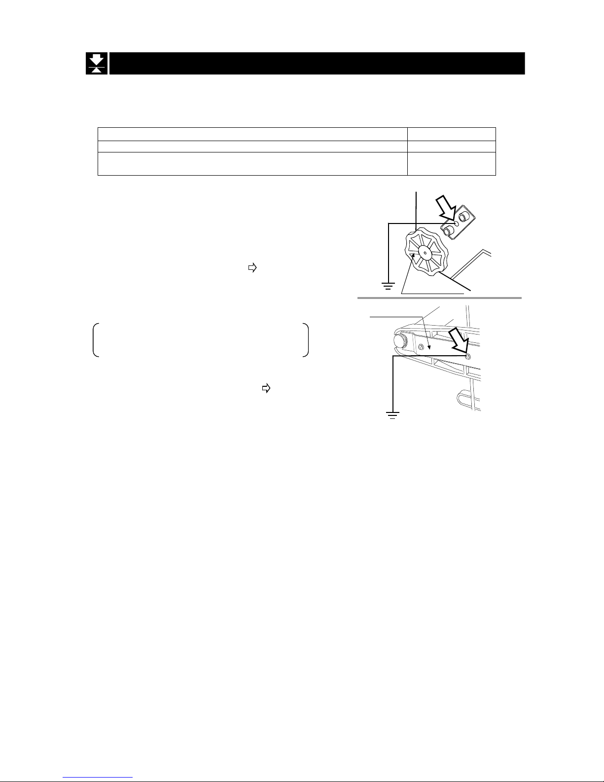
5.4. Grounding the scale
When using where there may be static electricity, ground the scale.
The grounding procedure depends on the scale model. Refer to the table below.
These procedures are only for grounding part of the scale.
Models Refer to
HV-15KC/HV-15KCP/ HW-10KC/HW-10KCP
Procedure A
HV-60KC/HV-60KCP/HV-200KC/HV-200KCP
HW-60KC/HW-60KCP/HW-100KC/HW-100KCP/HW-200KC/HW-200KCP
Procedure B
Procedure A
(
HV-15KC/HV-15KCP/HW-10KC/HW-10KCP
)
Secure the grounding cable using a M4 screw in the
screw hole between the two hexagon bolts on the
base unit bottom side. (Part of “ ”)
Procedure B
HV-60KC/HV-60KCP/HV-200KC/HV-200KCP
HW-60KC/HW-60KCP/HW-100KC/HW-100KCP
HW-200KC/HW-200KCP
Secure the grounding cable using the screw that
secures the under cover. (Part of “ ”)
Base unit
bottom side
Levering feet
Under cover Base unit
bottom side

HV/HW-C/CP Series Page 13
6. Description of Each Part
Models
Models
HV-15KC
HV-15KCP
HW-10KC
HW-10KCP HW-100KC HW-100KCP
HW-200KC HW-200KCP
HV-60KC HV-60KCP
HV-200KC HV-200KCP
HW-60KC HW-60KCP
Display Unit
Cap
Pole
Pan (Weighing Pan)
Leveling Foot
Base Unit
Display Unit
Cap
Pole
Type C
Battery Case
Type C
CAL switch
Calibrating the scale
to weigh correctly.
Bubble Spirit Level
Leveling Foot
Leveling Foot
Type CP
Caution
The certified mass is required.

Page 14 HV/HW-C/CP Series
6.1. Display and Symbols
Display and Symbols Description A
Stability mark
When the current weight value is stable, this mark is
displayed. It means a proper condition that this value is
readable.
A
A
A
A
Zero point mark
When the ZERO key is pressed with nothing on the pan,
this mark is displayed. The zero point is the fundamental
starting point to weigh anything.
A
A
A
A
Net mark
When the TARE key is pressed, this mark is displayed.
Used to indicate that the mass of the container placed
on the pan has been subtracted from the gross value.
A
A
A
Preset tare mark
While a tare with digital input is displayed, this mark
blinks.
A
Hold mark
While the display is held, this mark is displayed.
Accumulation mark
While the accumulation function is used, this mark is
displayed.
A
A
Low battery mark for type C
When the battery is depleted (becoming low voltage),
this mark is displayed. Replace with four new batteries.
A
A
A
Comparator indicator
When using the comparator function, the result is
indicated after the weight value is compared with the
upper and lower limits.
A
A
Zero point (Example)
When the ZERO key is pressed with nothing on the pan,
the zero point mark and the stability mark are displayed.
A
A
A
A
A
STABLE
ZERO
Weighed mass value unit
PT
HOLD
M+

HV/HW-C/CP Series Page 15
Example
PT
Display and Symbols Description A
Counting mode (Example)
This mode uses the stored unit mass and counts the
number of articles on the pan. The unit is .
A
A
A
A
Storing the unit mass for the counting mode (Example)
The unit mass is stored, using 20 pieces of samples.
The zero value means that no articles are on the pan.
A
A
A
A
Storing the unit mass for the counting mode (Example)
The unit mass is stored, using 10 pieces of samples.
Sign "-" means that something is placed on the pan.
A
A
A
A
Function settings (Example)
- Press the MODE key to select the item, and then press
the ENTER key to finalize the selection.
- Enter a parameter using the numerical keypad.
- Press the ENTER key to store the new parameters.
A
A
A
A
A
While preset tare setting (Example)
- Enter a setting value using the numerical keypad.
- Press the ENTER key to store the new tare.
A
A
A
A
Hold display (Example)
The hold display is set using Hold of the function table.
When the weight value is "nearly-zero" (within the zero
band) or changes more than 25% +30 digits, the hold is
canceled.
A
A
A
A
Weighing error
Check the base unit and the weighing pan.
A
A
A
A
Overload display
Remove anything that is on the pan.
A
A
A
A
Calibration error
The calibration mass is too light.
Check the base unit and the weighing pan.
A
A
A
A
The "digit" is a unit of display, and is equivalent to the minimum measurable mass.
The " nearly-zero " or zero band is within ±5 digits from zero point in the unit of kg.
Parameter
Item

Page 16 HV/HW-C/CP Series
and lighting up
Blinking
M+
Blinking
M+
Display and Symbols Description A
Calibration error
The calibration mass is too heavy.
Check the base unit and the weighing pan.
A
A
A
A
Does not display zero when the scale is turned on.
Remove anything that is on the weighing pan.
Perform zero point calibration.
Or
The weight value is unstable due to drift or vibration
when the scale is turned on.
A breeze or vibration may be affecting the
measurement.
Check around the weighing pan.
A
A
A
A
Accumulated data count A
A
Total mass value of the accumulated data A
A
e.g. CAP. MAX. 3/6/15kg d=1/2/5g
The weighing range and measurable minimum mass.
Example: Displays the weight value by 5 g up to 15 kg.
Displays the weight value by 2 g up to 6 kg.
Displays the weight value by 1 g up to 3 kg.
A
A
6.2. Keys
Display and Symbols Description A
ON/OFF key
The scale is in standby status when power is connected using
the AC adapter.
A
A
A
ZERO key
When the ZERO key is pressed with nothing on the pan, the
scale displays the mass value of zero and the zero point mark.
If the scale is in tare in this time, the tare value is cleared.
When accumulation is displayed, the accumulation is cleared.
A
A
A
A
TARE key
Canceling the mass of a container which is placed on the pan
and does not weigh its mass.
Note The tare reduces the weighing range.
A
A
A
Adds to the accumulated data.

HV/HW-C/CP Series Page 17
Display and Symbols Description
SET key
When setting the upper/lower limit, switch between + and -.
Enters preset tare setting mode
Performs paper feed at the built-in printer
Displays the accumulated results
Sets upper/lower limit values for comparator
Proceeds to unit mass storing when using counting mode
MODE key
- Switches the mode (unit) to be displayed
- The mode (unit) is maintained in non-volatile memory, so
the scale displays using the most recently used mode
(unit) when turning on the power next time
- Used as key to select the items at each setting.
HOLD key
Holds the display. Refer to function settings for details.
PRINT key
Prints out the value displayed or outputs it as data. However,
those operations differ depending on function settings.
Enters function settings
Display off
and
press
Press
and
hold
and
press
Press
and
hold
and
press
Press
and
hold
and
press
Press
and
hold
and
press
Press
and
hold
and
press
Press
and
hold

Page 18 HV/HW-C/CP Series
7. Basic Operation
7.1. Turning the Scale on/off and Weighing
7.1.1. When Using the AC Adapter
Step 1 Ground the scale.
Step 2 Confirm that nothing is placed on the pan.
Step 3 Confirm that local voltage and receptacle type are correct.
Step 4 The scale turns on/off using the ON/OFF key alternately.
Step 5 Check the accuracy of weighing. Allow 30-minute warm up before calibration.
Step 6 With nothing on the pan, press the ZERO key to display zero.
Step 7 Place an article to be weighed on the pan gently.
Step 8 Wait for the stability mark to be displayed. Read the weight value.
Step 9 Remove the article from the pan.
Step 10 Turn the scale off using the ON/OFF key.
Memo
With the AC adapter connected, the power is off at the scale, but not from the AC
adapter, after the scale is turned off using the ON/OFF key. To shut down the power
completely, disconnect the AC adapter.
AC adapter
This manual suits for next models
13
Table of contents
Other AND Scale manuals


AND
AND HV-CWP Series User manual

AND
AND PLUS CONNECT UC-350BLE User manual

AND
AND UC-352BLE User manual

AND
AND GX-L Series User manual

AND
AND HV-CWP Series User manual

AND
AND HR Series User manual

AND
AND UC-321 User manual

AND
AND UC-355PBT-Ci User manual

AND
AND FZ-i Series User manual

AND
AND BA-TE Series User manual


