AND UO-200 Parts list manual

UO-200
Setup / Operation Manual
Revision 1.0
Dec 8, 2005
2005 A&D Weighing
Contents subject to change without notice.
A&D Weighing
1555 McCandless Drive
Milpitas, CA 95131
Tel (800) 726-3364
Fax (408) 263-0119
E-mail: [email protected]
Web: www.andweighing.com
Visit www.balances.com Your Authorized A&D Dealer

NOTE
This equipment has been tested and found to comply with the limits for a Class A digital device,
pursuant to Part 15 of the FCC Rules. These limits are designed to provide reasonable protec-
tion against harmful interference when the equipment is operated in a commercial environment.
This equipment generates, uses and can radiate radio frequency energy and, if not installed and
used in accordance with the instructions manual, may cause harmful interference to radio com-
munications. Operation of this equipment in a residential area is likely to cause harmful interfer-
ence in which case the user will be required to correct the interference at his/her own expense.
Visit www.balances.com Your Authorized A&D Dealer

i
TABLE OF CONTENTS
Page
Chapter 1: Introduction to The UO-200........................................................................................... 1-1
Chapter 2: Installation ..................................................................................................................... 2-1
2.1 ABS Enclosure .............................................................................................................. 2-1
2.1.1 Connecting the weigh platform......................................................................... 2-1
2.1.2 Connecting the power supply........................................................................... 2-2
Chapter 3: Configuration ................................................................................................................. 3-1
3.1 Configuration Overview................................................................................................. 3-1
3.2 Setup (“F”) Menu ........................................................................................................... 3-1
3.2.1 Entering the Setup Menu ................................................................................. 3-1
3.2.2 Navigating in the Setup Menu .......................................................................... 3-1
3.2.3 Notes on the Setup Menu ................................................................................ 3-2
3.2.4 Exiting the Setup .............................................................................................. 3-2
3.3 User (“A”) Menu............................................................................................................. 3-3
3.3.1 Entering the User Menu ................................................................................... 3-3
3.3.2 Navigating in the User Menu............................................................................ 3-3
3.3.3 Notes on the User Menu .................................................................................. 3-4
3.3.4 Exiting the User Menu ...................................................................................... 3-4
Chapter 4: Setup Menu Descriptions and Procedures ................................................................... 4-1
4.1 Setup Menu Descriptions .............................................................................................. 4-1
4.2 Setup Menu Procedures ............................................................................................... 4-2
4.2.1 Graduation Entry (F1) ...................................................................................... 4-2
Chapter 5: User Menu Descriptions and Procedures ..................................................................... 5-1
5.1 User Menu Descriptions................................................................................................ 5-1
5.2 User Menu Procedures ................................................................................................. 5-1
5.2.1 Auto Power Off Entry (A10).............................................................................. 5-1
Visit www.balances.com Your Authorized A&D Dealer

ii
Chapter 6: Calibration ..................................................................................................................... 6-1
6.1 Calibration Overview ..................................................................................................... 6-1
6.2 Zero Calibration (F16) ................................................................................................... 6-1
6.3 Span Calibration (F17) .................................................................................................. 6-1
6.4 View Calibration Values (F18)....................................................................................... 6-2
6.5 Key-in Zero Calibration Value (F19) ............................................................................. 6-3
6.6 Key-in Span Calibration Value (F20) ............................................................................ 6-3
Chapter 7: Operation....................................................................................................................... 7-1
7.1 Display........................................................................................................................... 7-1
7.1.1 Liquid Crystal Display (LCD) ............................................................................ 7-1
7.2 Keyboard ....................................................................................................................... 7-2
7.2.1 Function Keys................................................................................................... 7-2
7.3 General Scale Operation............................................................................................... 7-2
7.3.1 Weighing an item.............................................................................................. 7-2
7.3.2 Taring an item .................................................................................................. 7-3
Appendix A: Specifications ................................................................................................................ A-1
Appendix B: Displayed Error Codes .................................................................................................. B-1
Visit www.balances.com Your Authorized A&D Dealer
Page 1-1
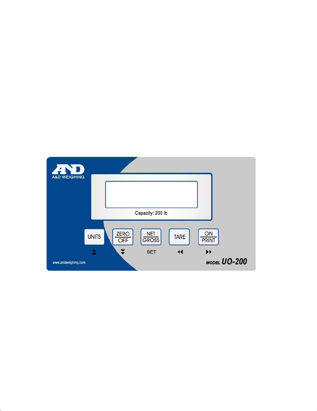
CHAPTER 1: INTRODUCTION TO THE UO-200 SCALE
The UO-200 Scale is a 200 lb x 0.5 lb capacity scale with built in motion compensation that al-
lows the user to obtain stable weight readings while the scale is moving.
All setup parameters may be entered via the front panel keys, including calibration.
The UO-200 is powered with six “C” cell alkaline batteries (not included). An AC adapter option is
also available.
Prior to using the UO-200, please read this manual carefully and completely. Store the manual in
a safe and convenient place so it will be available if you have questions concerning the operation
of the scale.
FIGURE 1-1: UO-200 Front Panel
Visit www.balances.com Your Authorized A&D Dealer

Page 2-1
CHAPTER 2: INSTALLATION
2.1 UO-200 INDICATOR HEAD
For indicators contained in the standard ABS enclosure, the rear panel of the UO-200 indicator
contains all connectors necessary to make the appropriate connections to the weigh platform and
power supply.
Figure 2-1: UO-200 ABS Enclosure Rear Panel
2.1.1 CONNECTING THE WEIGH PLATFORM
The UO-200 ships with a 7 ft shielded load cell cable for connected to the weigh platform’s
load cell.
1. Plug the cable’s 5-pin connector into the load cell port on the rear panel of the indicator.
2.1.2 CONNECTING THE POWER SUPPLY
1. Obtain six (6) alkaline “C” (UM-2) batteries and install them into the battery compartment
located at the rear of the unit. Thumbscrews are provided for quick access. Be sure to
observe the polarity indicated inside the battery holder.
2. If you do not wish to use batteries, you may use the optional AC adapter. Simply plug
the AC adapter into the indicator’s DC Power Jack first, and then plug into a standard
wall outlet. Make sure that the AC voltage appearing at the wall outlet matches the
input voltage marked on the AC adapter.
Visit www.balances.com Your Authorized A&D Dealer

Page 3-1
CHAPTER 3: CONFIGURATION
3.1 CONFIGURATION OVERVIEW
The UO-200 contains two main setup menus: The Setup (“F”) menu, which configures the UO-200
to your weigh platform and the User (“A”) menu, which enables some user options. The Setup and
User menus consist of several menu selections, each with its own sub-menu of choices.
To set up the UO-200, you must first enter the appropriate menu mode. Once there, four of the front panel keys
become directional navigators to move around in the menus, and one key is used to save or SET the
selections.
3.2 SETUP (“F”) MENU
3.2.1 ENTERING THE SETUP MENU
1. Power off the UO-200 by pressing and holding the ZERO/OFF key for about six
seconds.
2. On the rear panel move the Setup/Calibration Switch to the opposite position. See
Chapter 2 for location of the Setup/Calibration Switch.
3. Power on the UO-200. The indicator shows ” F 1” to indicate that you are in Setup
Menu mode.
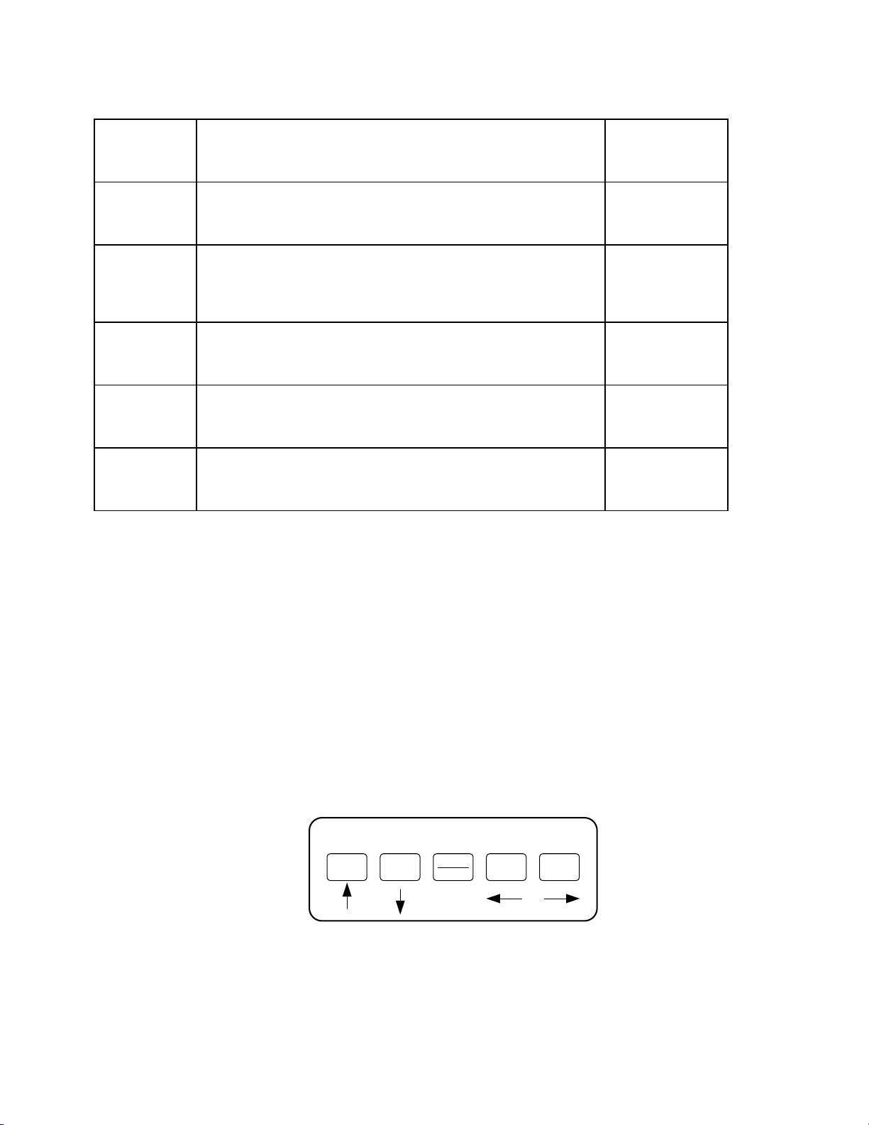
3.2.3 NAVIGATING IN THE SETUP MENU
Use the directional keys shown in Figure 3-1 to move around in the Setup Menu Chart
shown in Figure 3-2 on the following page.
1. To move to a new “F” heading, use the TARE (left) or ON/PRINT (right) key to move
right or left in the Setup Menu Chart.
2. To move to the selection level, press the ZERO/OFF (down) key once. The current
saved selection is shown.
3. To view the available selections for the current “F” heading, use the TARE (left) or
ON/PRINT (right) key to move through the selection field.
4. To save a new selection, press the NET/GROSS (Set) key .To exit without saving,
press the UNITS (up) key to return to the current “F” heading.
5. Repeat Steps 1 through 4 until the Setup Menu is programmed.
Visit www.balances.com Your Authorized A&D Dealer

Page 3-2
SET
Figure 3-1: Setup Menu Key Assignments
F1
Grads
F4
Zero Range
F5
Mot. Band
F6
Dig. Filter
F7
Ovld. Limit
1234
100% 1.9%
1d 3d …50d
F8
Calib. Unit
F9
Dsp. Div.
12
0.5d 1d 3d
0d 5d
F3
Zero Band
0d 2% 1d 9d
125
F10
Dec. Pt. F17
Span Calib.
F18
Cal. View
F19
Key-in Zero
F20
Key-in Span
00.0 0.00 0.000 0.0000 00
F16
Zero Calib.
Press ZERO
key to begin
056
Press ZERO
key to begin
Press ZERO
key to begin
Press ZERO
key to begin
Press ZERO
key to begin
78
Press ZERO
key to begin
Figure 3-2: Setup Menu Chart
3.2.4 NOTES ON THE SETUP MENU
1. There is also an F21 sub-menu present that is for FACTORY USE ONLY!
2. Detailed descriptions of the setup menu parameters can be found in Chapter 4 of this
manual.
3. The User (“A”) menu sub-menus appear when scrolling left or right from the “F” menu.
3.2.5 EXITING THE SETUP MENU
1. Power off the indicator.
2. On the rear panel, move the Setup/Calibration Switch back to its original position.
3. Power on the indicator. The display will go through a digit check, then settle into Normal
Operating mode. All front panel keys will now return to their normal mode of operation.
Visit www.balances.com Your Authorized A&D Dealer

Page 3-3
3.3 USER (“A”) MENU
3.3.1 ENTERING THE USER MENU
NOTE: The UO-200 only supports the A5 (Units Key) and A10 (Auto Power Off) functions. Please
disregard the other listed functions.
1. Enter the Setup (“F”) menu by following the directions in Section 3.2.1 or 3.2.2.
2. Use the right or left directional keys shown in Figure 3-3 to move right or left in the
Setup (“F”) menu until the indicator shows ” A 1”.
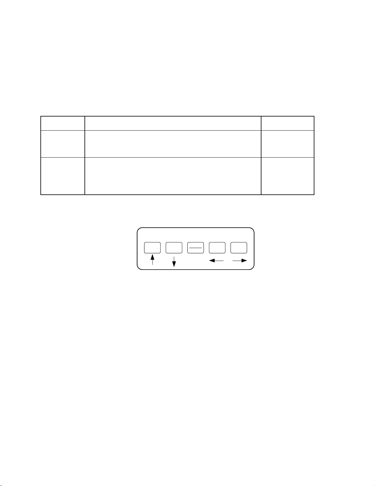
3.3.2 NAVIGATING IN THE USER MENU
Use the directional keys shown in Figure 3-3 to move around in the User Menu Chart shown
in Figure 3-4 on the following page.
1. To move to a new “A” heading, use the TARE (left) or ON/PRINT (right) key to move
right or left in the User Menu Chart.
2. To move to the selection level, press the ZERO/OFF (down) key once. The current
saved selection is shown.
3. To view the available selections for the current “A” heading, use the TARE (left) or
ON/PRINT (right) key to move through the selection field.
4. To save a new selection, press the NET/GROSS (Set) key .To exit without saving,
press the UNITS (up) key to return to the current “A” heading.
5. Repeat Steps 2 through 5 until the User Menu is programmed.
SET
Figure 3-3: User Menu Key Assignments
Continued =>
Visit www.balances.com Your Authorized A&D Dealer

Page 3-4
A1
Baud Rate
A2
Data Bits, Parity
A4
Display Check
A5
Units Key
C d
A6
Serial Port Mode
1200 2400 4800 9600
7O 7E 7n8n
A3
Serial Trans Mode
A8
ID No Entry
A10
A
uto Power Off
A7
ID No Enable
19200
Press ZERO
key to begin
01
A11
Hold Mode
0101Press ZERO
key to begin
A9
No of LF
Press ZERO
key to begin
Press ZERO
key to begin
0
A12
Backlight
01
A13
Handshaking
0 1
A14
Print Header
0 1
A15
Time Enable
0 1
A16
Time Format
01
A17
Time Entry
A18
Data Enable
0 1
A19
Date Format
0 1
A20
Date Entry
Press ZERO
key to begin
Press ZERO
key to begin
12
Figure 3-4: User Menu Chart
3.3.3 NOTES ON THE USER MENU
1. Detailed descriptions of the user menu parameters can be found in Chapter 5 of this manual.
3.3.4 EXITING THE USER MENU
1. Exit the User (“A”) menu by following the directions in Section 3.2.5 or 3.2.6. The display will go
through a digit check, then settle into Normal Operating mode. All front panel keys will now return to
their normal mode of operation.
Visit www.balances.com Your Authorized A&D Dealer

Page 4-1
CHAPTER 4: SETUP MENU DESCRIPTIONS AND PROCEDURES
4.1 SETUP MENU DESCRIPTIONS
This section provides more detailed descriptions of the selections found in the Setup Menu Chart.
Factory-set defaults are shown in bold with a checkmark (√).
NAME/CODE DESCRIPTION CODE/VALUE
F1
Graduations
Specifies number of full-scale graduations. Value should be consis-
tent with legal requirements and environmental limits on the useful
system resolution. Pressing the ZERO key to scroll down one level
begins the sequence.
100 - 50000
400√
F3
Zero Track
Band
Selects the range within which the scale will automatically zero. Note
that the scale must be in standstill to automatically zero. Selections
are in Display Divisions.
0d
0.5d
1d
3d√
5d
F4
Zero Range
Selects the range within which the scale may be zeroed. Note that the
indicator must be in standstill to zero the scale.
100%√
1.9%
F5
Motion Band
Sets the level at which motion is detected by comparing the present
display update with the previous one. If motion is not detected for two
seconds or more, scale is in standstill and can process a Print or Zero
command. Maximum value varies depending on local regulations.
1d
3d√
5d
10d
15 d 20d
30d 40d
50d
F6
Digital Filter
Averages weight readings to produce higher stability. The higher the
filter setting, the greater the stability.
0 1
2 3
4 5
6 7
8√
F7
Overload Limit
Selects the desired formula which determines the point at which the
indicator shows overload. All selections are based on the primary unit
selected in F8.
"FS" = Full scale in primary units.
FS
FS + 2%√
FS + 1d
FS + 9d
F8
Calib. Unit
Selects the primary base unit to be used in the calibration process.
Also the default unit for normal operation.
"1" = primary unit is lb. "2" = primary unit is in kg.
1√
2
F9
Display
Divisions
Determines the desired weight increments. Value should be consis-
tent with legal requirements.
1
2
5√
F10
Decimal Pt.
Determines location of the decimal point. 0 0.0√
0.00 0.000
0.0000 00
Visit www.balances.com Your Authorized A&D Dealer
Page 4-2
F16
Zero Calibra-
tion
Places indicator into the zero calibration routine. Scrolling down with
the ZERO key one level begins the procedure.
Press ZERO key
to begin sequence
F17
Span Calibra-
tion
Places indicator into the span calibration routine. Scrolling down with
the ZERO key one level begins the procedure.
Press ZERO key
to begin sequence
F18
View Calibra-
tion
Actuates the function that allows you to view both the zero and span
calibration value. The values displayed in this function are valid only
after Calibration (F16 & F17) has been successfully completed.
Scrolling down with the ZERO key one level begins the procedure.
Press ZERO key
to begin sequence
F19
Key-in Zero
Allows you to key-in known zero calibration value in case of memory
loss in the field. Scrolling down with the ZERO key one level begins
the procedure.
Press ZERO key
to begin sequence
F20
Key-in Span
Allows you to key-in a known span calibration value in case of mem-
ory loss in the field. Scrolling down with the ZERO key one level be-
gins the procedure.
Press ZERO key
to begin sequence
F21
Factory Reset
This sub-menu will reset all parameters in the “F” and “A” menu to the
default settings. USE WITH CAUTION!
Press the ZERO
key twice to exe-
cute.
4.2 SETUP MENU PROCEDURES
This section provides instructions for all of the Setup Menu procedures except for the calibration
related menus, which are documented in Chapter 6.
4.2.1 Graduation Entry (F1)
1. While in the Setup Menu mode, scroll to "F 1", then scroll down once using the
ZERO/OFF key to enter the Graduation menu.
2. The display will display a value with one flashing digit. This value will be the current
graduation value.
3. Use the four directional keys (shown in Figure 4-1 below) to adjust the displayed
value to the actual graduation value. Increase the flashing digit by pressing the
UNITS key. Decrease the flashing digit by pressing the ZERO/OFF key. Pressing
the ON/PRINT key or the TARE key will change the position of the flashing digit.
SETUP MODE KEY FUNCTIONS
ZERO GROSS
NET TARE PRINT
SET
UNITS
Figure 4-1: Setup Menu Key Assignments
4. After setting the exact value, press the NET/GROSS key to save the graduation
value. The display will show "SET" momentarily, then revert back up to F1.
NOTE: The indicator will accept values only in the range from 100 to 50000.
Visit www.balances.com Your Authorized A&D Dealer
Page 5-1
CHAPTER 5: USER MENU DESCRIPTIONS AND PROCEDURES
NOTE: The UO-200 only supports the A5 (Units Key) and A10 (Auto Power Off) functions. Please
disregard the other listed functions.
5.1 USER MENU DESCRIPTIONS
This section provides more detailed descriptions of the selections found in the User Menu Chart.
Factory-set defaults are shown in bold with a checkmark (√).
NAME/CODE DESCRIPTION CODE/VALUE
A5
Disable the
UNITS Key
Allows the UNITS key to be disabled so that an operator cannot
accidentally press the key and change the displayed units.
"0" = Disable the Units key "1" = Enable the Units key
0
1√
A10
Auto Power Off
Actuates the function that allows entry of the desired automatic turn
off time in minutes. Pressing the ZERO key to scroll down one level
begins the sequence.
“0” = Disabled (Always ON)
0 - 30
2√
5.2 USER MENU PROCEDURES
USER MODE KEY FUNCTIONS
ZERO GROSS
NET TARE PRINT
SET
UNITS
Figure 5-1: User Menu Key Assignments
5.2.1 Auto Power Off Entry (A10)
1. While in the User Menu mode, scroll to "A 10", then scroll down once using the
ZERO/OFF key to enter the Auto Power Off menu.
2. The display will momentarily show the current line feeds value.
3. Use the four directional keys (shown in Figure 5-1 above) to adjust the displayed
value to the actual auto power off value. Increase the flashing digit by pressing the
UNITS key. Decrease the flashing digit by pressing the ZERO/OFF key. Pressing
the ON/PRINT key or the TARE key will change the position of the flashing digit.
4. After setting the exact value, press the NET/GROSS key to save the auto power off
value. The display will show "SET" momentarily, then revert back up to A10.
Visit www.balances.com Your Authorized A&D Dealer

Page 6-1
CHAPTER 6: CALIBRATION
6.1 CALIBRATION OVERVIEW
The indicator is calibrated by following the procedures embedded in F16 (Zero) and F17 (Span) of
the Setup Menu. Each procedure enters a value into the indicator's non-volatile memory - F16 the
zero value (deadweight) and F17 the span value (test weight). The minimum test weight that can be
used is 1% of full-scale capacity. The indicator allows for multi-point calibration in F17. These three
calibration points are denoted C1-C3. You may use C1 only if you like. If you do use all three
calibration points, then they must be in ascending order, e.g. 2,000, 5,000 and 10,000 pounds.
After the two calibration procedures are executed successfully, you should record all calibration
values in Table 6-1 using the F18 View procedure.
In the unlikely event that either value is lost while in the field, the setup menu makes provisions for
re-entering these values via F19 and F20, thus eliminating the need for re-calibration with test
weights.
NOTE: This chapter assumes that the indicator is in Setup (“F”) Menu mode. If the indicator is not
in Setup Menu mode, refer to Chapter 3 for instructions.
6.2 ZERO CALIBRATION (F16)
1. While in the Setup mode, scroll to "F 16", then scroll down once using the ZERO key to enter
zero calibration menu. The display will momentarily show "C 0" followed by a value. This value
is the internal A/D count and can prove useful when trying to troubleshoot setup problems.
2. After making sure that there are no test weights on the platform, press the ZERO key again to
zero out the displayed value.
3. Press the NET/GROSS key to save the zero point value. The display will show "EndC0"
momentarily, then revert back up to F16. At this time, proceed to the F17 span calibration to
complete indicator calibration.
6.3 SPAN CALIBRATION (F17)
1. While in the Setup mode, scroll to "F 17", then scroll down once using the ZERO key to enter
span calibration menu. The display will momentarily show "C 1" for the first span calibration,
followed by a value with one flashing digit. This value will be zero with the Decimal Point
parameter selected in F10.
2. Place the test weight on the weighing mechanism.
3. Use the four directional keys (shown in Figure 6-1 below) to adjust the displayed value to the
actual test weight value. Increase the flashing digit by pressing the UNITS key. Decrease the
flashing digit by pressing the ZERO/OFF key. Pressing the ON/PRINT key or the TARE key will
change the position of the flashing digit.
SETUP MODE KEY FUNCTIONS
ZERO GROSS
NET TARE PRINT
SET
UNITS
Figure 6-1: Setup Menu Key Assignments
Visit www.balances.com Your Authorized A&D Dealer

Page 6-2
4. After setting the exact value, press the NET/GROSS key to save the value. If the calibration
was successful, the display will show "EndC1" momentarily, momentarily, followed by "C 2" for
the second calibration point.
5. Repeat steps 2-4 for C2 and C3. At the conclusion of C3, the indicator reverts back up to F17.
NOTE: If you wish to use only one calibration point (C1), simply press the NET/GROSS key
when prompted for C2 or C3.
6. At this time it is suggested that the calibration values be recorded for future use (see Section
6.4).
7. If the calibration was not successful, one of the error messages below will appear. Take the
indicated action to correct the problem, then perform a new calibration.
"Err0" - The calibration test weight or the adjusted keyed-in weight is larger than the full
capacity of the scale. Change the calibration test weight or check the input data.
"Err1" - The calibration test weight or the adjusted keyed-in weight is smaller than 1% of the full
capacity of the scale. Change the calibration test weight or check the input data.
"Err2" - The internal resolution of the scale is not high enough to accept the calibration value.
Check your load cell connections.
6.4 VIEW CALIBRATION VALUES (F18)
Note: The values displayed in this procedure are valid only after a successful calibration has been
performed using F16 and F17.
1. While in the Setup mode, scroll to "F 18", then scroll down once using the ZERO key to enter
View calibration menu.
2. The display will show the information listed in Table 6-1. The code will display briefly followed
by the value. It is recommended that you record each value in the table below. Press any key to
continue down the list. At the completion of the list, the indicator reverts back up to F18.
CODE NAME VALUE
C 0 Zero Calibration Value
T 1 First Test Weight Value
C 1 First Span Calibration Value
T 2 Second Test Weight Value
C 2 Second Span Calibration Value
T 3 Third Test Weight Value
C 3 Third Span Calibration Value
Table 6-1: Calibration Value Table
Visit www.balances.com Your Authorized A&D Dealer

Page 6-3
6.5 KEY-IN ZERO CALIBRATION VALUE (F19)
Note: This procedure is intended for emergency use only in the case of non-volatile memory loss.
A valid zero calibration value, obtained from a successful F16 calibration procedure, must
be used.
1. While in the Setup mode, scroll to "F 19", then scroll down once using the ZERO key.
2. The display will momentarily show "CAL 0", followed by a flashing zero. Use the four
directional keys (shown in Figure 6-1) to adjust the displayed value to the zero calibration
value.
3. After setting the exact value, press the NET/GROSS key to save the value.
4. The display will show "E CAL 0" momentarily, then revert back up to F19.
6.6 KEY-IN SPAN CALIBRATION VALUE (F20)
Note: This procedure is intended for emergency use only in the case of non-volatile memory loss.
A valid span calibration value, obtained from a successful F17 calibration procedure, must
be used.
1. While in the Setup mode, scroll to "F 20", then scroll down once using the ZERO/OFF key. The
indicator will prompt you to enter the information in Table 6-2.
2. If the value shown is correct, press the ZERO/OFF key to move to the next parameter.
Otherwise, Use the four directional keys (shown in Figure 6-1) to adjust the displayed value to
the span calibration value.
3. After setting the exact value, press the NET/GROSS key to save the value.
4. If the entered values are entered successfully, the display will show "E" momentarily before
continuing to the next parameter. At the completion of the sequence, the indicator will then
revert back up to F20.
CODE NAME
ET T 1 First Test Weight Value
ET C 1 First Span Calibration Value
ET T 2 Second Test Weight Value
ET C 2 Second Span Calibration Value
ET T 3 Third Test Weight Value
ET C 3 Third Span Calibration Value
Table 6-2: Calibration Value Entry Table
Visit www.balances.com Your Authorized A&D Dealer
Page 7-1
CHAPTER 7: OPERATION
7.1 DISPLAY
The UO-200 utilizes a 6 digit LCD (Liquid Crystal Display). Typically, LCD’s are used for outdoor ap-
plications while LED’s are used indoors where brightness is needed. Table 7-1 summarizes the dis-
play annunciators.
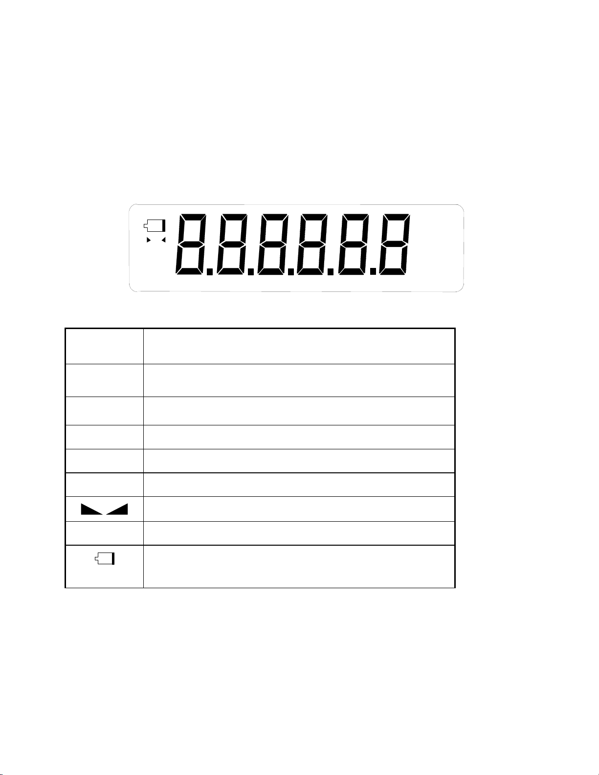
7.1.1 LIQUID CRYSTAL DISPLAY (LCD)
Figure 7-1 shows the display detail of the LCD indicators.
oz
lb
pcs
%
kg
GN
O
PT
FIGURE 7-1: UO-200 LCD Detail
LCD Annun-
ciator
MEANING
Î0ÍBetter known as the “Center of Zero” annunciator, this light is active when-
ever the displayed weight is within ± 0.25 divisions of true zero.
N Indicates that the indicator is displaying net weight.
G Indicates that the indicator is displaying gross weight.
T Indicates that a tare weight has been established in the system.
lb, kg Indicates the unit of the displayed weight. PCS stands for “pieces”.
This light is on whenever the scale is stable.
P Indicates that the indicator is displaying peak weight
Flashes when the battery voltage is too low for normal operation. For stan-
dard units, replace the batteries. For rechargeable units, re-charge the bat-
tery.
TABLE 7-1: UO-200 Annunciator Definitions
Visit www.balances.com Your Authorized A&D Dealer

Page 7-2
7.2 KEYBOARD
The keyboard is composed of five function keys. Refer to Figures 7-2 for the overall layout and key
locations.
FIGURE 7-2: Function Keys Layout
7.2.1 FUNCTION KEYS
Units – This key toggles the indicator between lb and kg if enabled in the User (“A”) menu.
See Chapter 5 for more information.
Zero/OFF - When held for six seconds shuts the indicator off. Otherwise, this key sets the in-
dicator to display zero provided the following conditions are met:
1. The indicator is displaying Gross weight.
2. The displayed weight is within the zero reset range that is programmed in F4 of the Setup
(“F”) Menu.
3. The scale is not in overload (see Appendix B for error codes).
Net/Gross - This key toggles the indicator between Gross weight and Net weight only if a
Tare has been established.
Tare - This key is used to establish a Tare provided the following conditions are met:
1. The indicator is not at or below Gross zero.
2. The scale is not in overload (see Appendix B for error codes).
ON/Print – When off, turns the indicator on. The Print function is not available on the UO-
200.
7.3 GENERAL SCALE OPERATION
7.3.1 WEIGHING AN ITEM
1. Select the desired weighing unit by pressing the UNITS key until that unit is indicated on
the display.
2. If necessary, press the ZERO/OFF key to obtain a weight reading of zero.
3. Place the object to be weighed on the scale’s platter and allow the weight indication to
stabilize. If the item weight exceeds the scale’s weight capacity, it displays “000000”.
4. Read the weight shown on the display.
UNITS ZERO
OFF
NET
GROSS TARE ON
PRINT
Visit www.balances.com Your Authorized A&D Dealer

Page 7-3
7.3.2 TARING AN ITEM
To weigh an item in a container, the weight of that container must first be subtracted from the
overall weight to obtain an accurate weight reading. This is known as taring.
1. Select the desired weighing unit by pressing the UNITS key until that unit is indicated on
the display.
2. If necessary, press the ZERO/OFF key to obtain a weight reading of zero.
3. Place the empty container on the scale’s platter and allow the weight indication to stabi-
lize.
4. Press the TARE key. The display shows zero weight and turns the NET annunciator on.
5. Place the material to be weighed in the container and allow the weight indication to stabi-
lize.
6. Read the weight shown on the display.
7. You may toggle between the gross weight and the net weight by pressing the
NET/GROSS key.
Visit www.balances.com Your Authorized A&D Dealer

Page A-1
APPENDIX A: SPECIFICATIONS
ANALOG SPECIFICATIONS
Full Scale Input Signal 10mV, including dead load
Minimum Sensitivity - Non H-44 0.4 µV / grad
Minimum Sensitivity - H-44 Not applicable
Input Impedance 30MΩ, typical
Internal Resolution Approximately 245,000 counts at 3 mV/V
Display Resolution 50,000 display division max
Measurement Rate 15 Meas/sec, nominal
System Linearity Within 0.02% of FS
Calibration Method Software Calibration, with long term storage in EEPROM
Excitation Voltage +3.3 VDC, 4 x 350Ωload cells
DIGITAL SPECIFICATIONS
Microcontroller TI MSP430F447
Program Memory 32K x 8, internal to µC
SRAM: 1Kx 8, internal to µC
EEPROM: 256 x 8, external to µC
Digital Filtering Software selectable
OPERATOR INTERFACE
Display 0.8" (20 mm) 7-segment, Liquid Crystal, 6 Digit
Additional Symbols Net, Gross, Stable, Tare, lb, kg, Zero
Keyboard 5-key flat membrane panel
POWER
Alkaline Batteries 6 x “C” Size (UM-2) Cells
AC Adapter 9 VDC, 500mA Female
DC Power Consumption 12mA + 10mA/350ΩLoad Cell
ENVIRONMENTAL
Operating Temperature –10° to +40°C
Storage Temperature -25° to +70°C
Visit www.balances.com Your Authorized A&D Dealer
This manual suits for next models
1
Table of contents
Other AND Scale manuals

AND
AND HV-CWP Series User manual

AND
AND HL-WP Series User manual

AND
AND BA-TE Series User manual

AND
AND LifeSource UC-350CNBLE User manual

AND
AND UC-321 User manual

AND
AND UC-355PBT-Ci User manual

AND
AND AD-4212F Series User manual

AND
AND HL-200 User manual

AND
AND EJ-120 User manual

AND
AND UC-324ANT User manual


