Anthos A6 PLUS Series User manual

97055066
Rev. 00
2019-03
OPERATOR'S MANUAL
A5 - A6 PLUS - L6
EN
.

A5 - A6 PLUS - L6
2
EN
INDEX
1. GENERAL WARNINGS................................................................................................................................................................................... 4
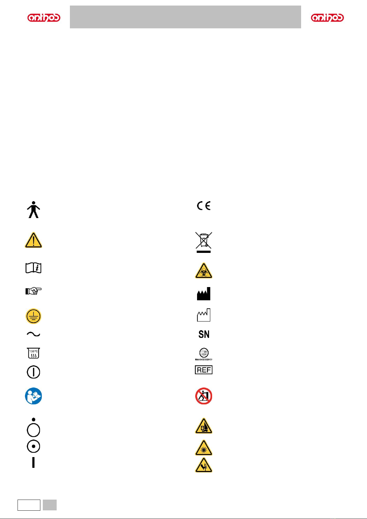
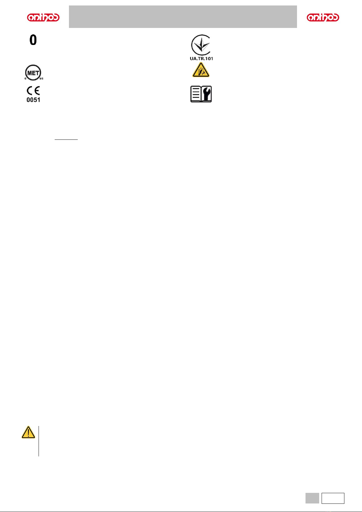
1.1. SYMBOLS...................................................................................................................................................................................................4
1.2. INTENDED USE .........................................................................................................................................................................................5
1.2.1. CLASSIFICATION AND REFERENCE STANDARDS ........................................................................................................................6
1.2.2. ENVIRONMENTAL CONDITIONS......................................................................................................................................................6
1.2.2.1. STORAGE CONDITIONS...................................................................................................................................................................6
1.2.3. WARRANTY.......................................................................................................................................................................................6
1.2.4. DISPOSING THE EQUIPMENT WHEN NO LONGER USED.............................................................................................................6
1.3. SAFETY WARNINGS..................................................................................................................................................................................7
1.4. ELECTROMAGNETIC SAFETY..................................................................................................................................................................8
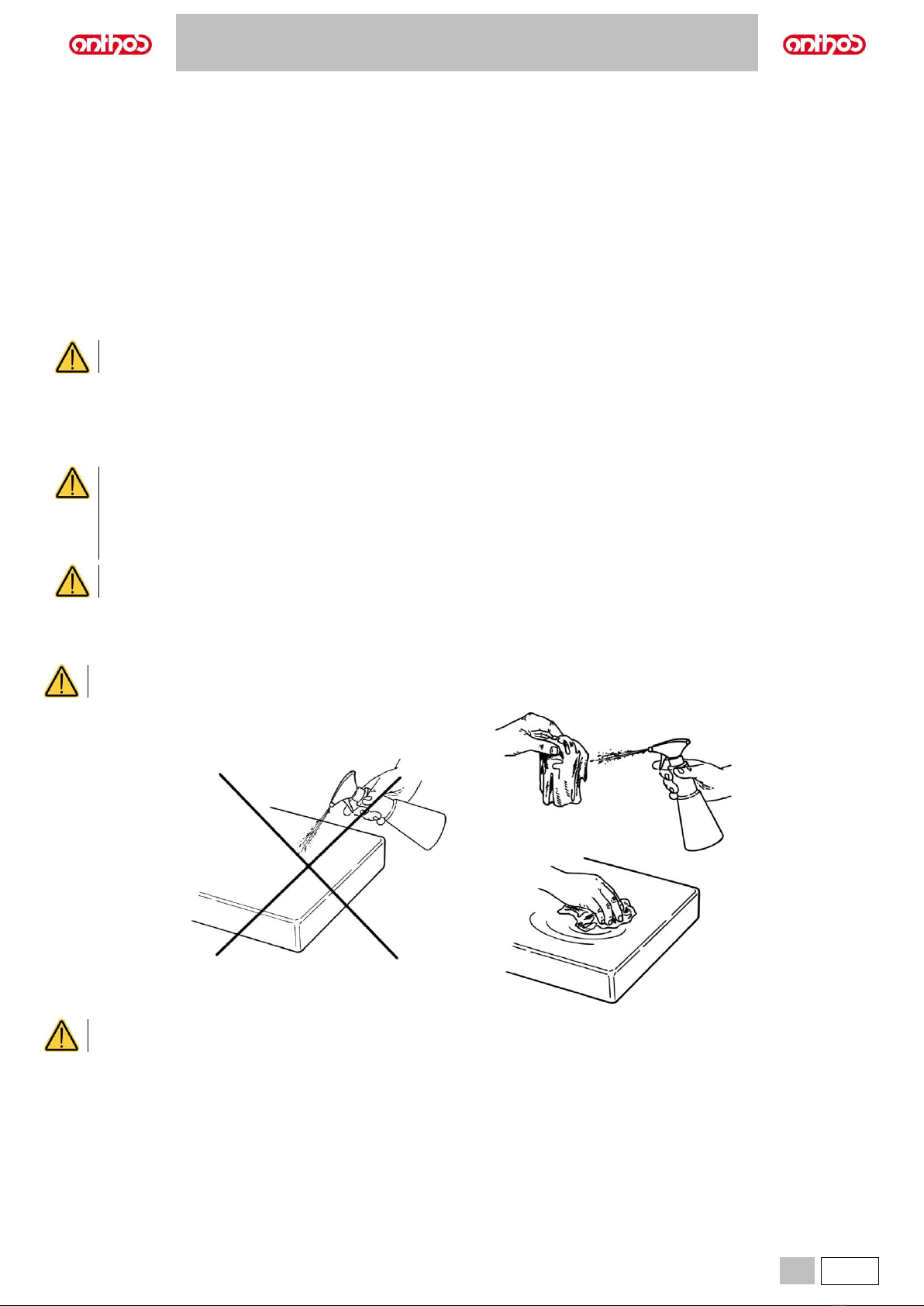
1.5. CLEANING AND DISINFECTION................................................................................................................................................................9
1.6. STERILISATION.......................................................................................................................................................................................10
2. DESCRIPTION OF THE EQUIPMENT........................................................................................................................................................... 10
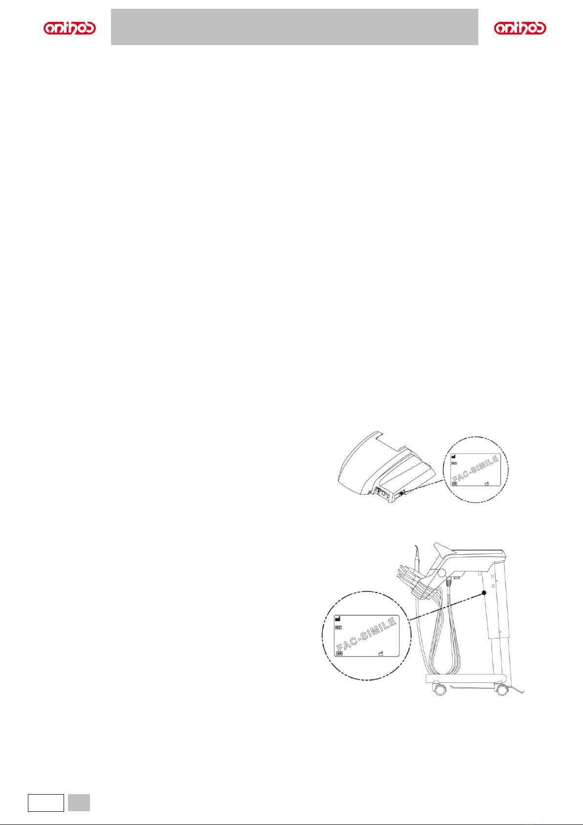
2.1. IDENTIFICATION PLATES.......................................................................................................................................................................10
2.2. DENTAL UNITS........................................................................................................................................................................................11
2.3. DENTAL CHAIR........................................................................................................................................................................................15
2.4. SPECIAL WARNINGS ..............................................................................................................................................................................16
3. STARTING..................................................................................................................................................................................................... 17
3.1. CONVERSION OF THE DENTAL UNIT CONFIGURATION FOR LEFT-HANDED OPERATORS (HYBRID version only).........................18
4. DENTAL CHAIR OPERATION ...................................................................................................................................................................... 19
4.1. SAFETY DEVICES....................................................................................................................................................................................19
4.2. MOVEMENT LOCK DEVICES ..................................................................................................................................................................20
4.3. ADJUSTABLE HEADREST.......................................................................................................................................................................21
4.4. MOVABLE ARMRESTS (OPTIONAL).......................................................................................................................................................21
5. DENTIST'S BOARD OPERATION................................................................................................................................................................. 22
5.1. DENTIST’S CONTROL CONSOLE ...........................................................................................................................................................25
5.1.1. MAIN SETTINGS .............................................................................................................................................................................27
5.1.1.1. HYGIENE CYCLE SETTING............................................................................................................................................................27
5.1.1.1.1. QUICK FLUSHING CYCLE SETTING...................................................................................................................................27
5.1.1.1.2. LONG FLUSHING CYCLE SETTING....................................................................................................................................27
5.1.1.1.3. BIOSTER DISINFECTION CYCLE SETTING .......................................................................................................................28
5.1.1.1.4. W.H.E. SYSTEM TANK EMPTYING.....................................................................................................................................28
5.1.1.2. STOPWATCH ..................................................................................................................................................................................28
5.1.2. OPERATOR SELECTION................................................................................................................................................................29
5.1.3. DENTAL CHAIR "RINSING POSITION" AND "RESET POSITION" PROGRAMMING......................................................................29
5.1.4. PROGRAMMING THE DENTAL CHAIR POSITIONS A, B, C and D................................................................................................29
5.1.5. EMERGENCY BUTTON...................................................................................................................................................................30
5.1.6. TURNING ON THE OPERATING LIGHT..........................................................................................................................................30
5.1.7. CONSOLE CONTROL PANEL LOCKING BUTTON.........................................................................................................................30
5.2. FOOT CONTROL......................................................................................................................................................................................31
5.2.1. "MULTIFUNCTION” FOOT CONTROL.............................................................................................................................................31
5.2.2. "PUSH-PEDAL” FOOT CONTROL...................................................................................................................................................33
5.2.3. "POWER PEDAL" FOOT CONTROL................................................................................................................................................35
5.2.4. WIRELESS FOOT CONTROL..........................................................................................................................................................37
5.3. SYRINGE..................................................................................................................................................................................................39
5.4. TURBINE..................................................................................................................................................................................................40
5.5. ELECTRIC MICROMOTOR ......................................................................................................................................................................41
5.5.1. RESTORATIVE OPERATING MODE...............................................................................................................................................43
5.5.2. ENDODONTIC OPERATING MODE................................................................................................................................................43
5.6. SCALER....................................................................................................................................................................................................45
5.7. T LED CURING LIGHT..............................................................................................................................................................................47
5.8. C-U2 DENTAL CAMERA...........................................................................................................................................................................51
5.9. ELECTRONIC APEX LOCATOR...............................................................................................................................................................55
5.10. ZEN-Xi INTEGRATED SENSOR...............................................................................................................................................................56
6. ASSISTANT’S BOARD OPERATION............................................................................................................................................................ 57
6.1. ASSISTANT’S BOARD CONSOLE ...........................................................................................................................................................59
6.2. INSTRUMENTS ON ASSISTANT’S BOARD.............................................................................................................................................59
6.3. SUCTION TUBES.....................................................................................................................................................................................60
6.4. TRAY HOLDER.........................................................................................................................................................................................61
6.5. HYDRAULIC SALIVA EJECTOR...............................................................................................................................................................61
7. WATER UNIT OPERATION........................................................................................................................................................................... 62
7.1. FILL CUP AND BOWL ..............................................................................................................................................................................62
7.2. S.H.S/S SYSTEM (SIMPLIFIED HYGIENIZATION SYSTEM)...................................................................................................................64
7.2.1. MANUAL S.H.S. SYSTEM (applied on A5 SINGLE CART model only) ............................................................................................65
7.3. W.H.E. SYSTEM (WATER HYGIENIZATION EQUIPMENT).....................................................................................................................66
7.4. BIOSTER S AUTOMATIC DISINFECTION SYSTEM (only dental units with LCD Touch DISPLAY)..........................................................68
7.5. AUTOMATIC INSTRUMENT FLUSHING CYCLE......................................................................................................................................70
7.6. A.C.V.S. SYSTEM (AUTOMATIC CLEANING VACUUM SYSTEM) ..........................................................................................................71
7.7. OPENING/CLOSING THE WATER UNIT SIDE COVER...........................................................................................................................72

A5 - A6 PLUS - L6
EN
3
8. ACCESSORIES............................................................................................................................................................................................. 72
8.1. OPERATING LAMP ..................................................................................................................................................................................72
8.2. MONITOR ON LAMP POLE......................................................................................................................................................................72
8.3. NEGATOSCOPE FOR PANORAMIC X-RAYS..........................................................................................................................................73
8.4. AIR/WATER/230V QUICK-COUPLINGS...................................................................................................................................................73
8.5. AUXILIARY TRAY HOLDER .....................................................................................................................................................................74
9. MAINTENANCE............................................................................................................................................................................................. 75
9.1. MAINTAINING THE INSTRUMENTS........................................................................................................................................................75
9.2. DRAINING CONDENSATE.......................................................................................................................................................................75
9.3. SUCTION FILTER CLEANING..................................................................................................................................................................76
9.4. SUCTION LINES.......................................................................................................................................................................................77
9.5. AIR-LIQUID SEPARATOR CANISTER BY CATTANI................................................................................................................................78
9.6. CLEANING THE TURBINE RETURN AIR FILTER....................................................................................................................................79
9.7. METASYS AMALGAM SEPARATOR........................................................................................................................................................80
9.8. DÜRR AMALGAM SEPARATOR ..............................................................................................................................................................80
9.9. DENTAL CHAIR........................................................................................................................................................................................80
9.10. CATTANI GRAVITY AMALAGAM SEPARATOR (dental units of A5 and A6 PLUS model only)................................................................80
10. WARNING/ERROR MESSAGES................................................................................................................................................................... 81
11. TECHNICAL DATA........................................................................................................................................................................................ 84
11.1. A5 CONTINENTAL DIMENSIONAL CHARACTERISTICS........................................................................................................................87
11.2. A5 INTERNATIONAL DIMENSIONAL CHARACTERISTICS.....................................................................................................................88
11.3. DIMENSIONAL CHARACTERISTICS OF A5 CART MODEL....................................................................................................................89
11.4. DIMENSIONAL CHARACTERISTICS OF A5 SINGLE CART MODEL ......................................................................................................90
11.5. DIMENSIONAL CHARACTERISTICS OF A5 SINGLE WATER UNIT MODEL..........................................................................................91
11.6. A6 PLUS CONTINENTAL MODEL DIMENSIONAL CHARACTERISTICS.................................................................................................92
11.7. A6 PLUS INTERNATIONAL MODEL DIMENSIONAL CHARACTERISTICS .............................................................................................93
11.8. DIMENSIONAL CHARACTERISTICS OF L6 CONTINENTAL MODEL .....................................................................................................94
11.9. DIMENSIONAL CHARACTERISTICS OF L6 CONTINENTAL MODEL in HYBRID version.......................................................................95
11.10. DIMENSIONAL CHARACTERISTICS OF L6 SIDE DELIVERY MODEL ..............................................................................................96
12. DENTAL UNIT MAINTENANCE SCHEDULE................................................................................................................................................ 97

A5 - A6 PLUS - L6
4
EN
1. GENERAL WARNINGS
•These instructions explain how to correctly use the following dental unit:
A5
A6 PLUS
L6
A5 CONTINENTAL
A6 PLUS CONTINENTAL
L6 CONTINENTAL
A5 INTERNATIONAL
A6 PLUS INTERNATIONAL
L6 SIDE DELIVERY
A5 CART
A5 SINGLE CART
A5 SINGLE WATER UNIT
Please carefully read this manual before using the device.
•The dental units described in this manual are manufactured by CEFLA s.c. - via Selice Provinciale 23/A - 40026 Imola (BO) Italia, a manufacturer
complying with the European Directive on medical devices.
•These instructions describe all the versions of the dental units with the maximum possible accessories, therefore not all the paragraphs are applicable
to the unit you have purchased.
•The information, technical specifications and illustrations contained in this publication are not binding.
CEFLA s.c. reserves the right to introduce modifications and technical improvements without having to modify these instructions.
•The manufacturer has a company policy of continual development. Although every effort is made to keep technical documentation up-to-date at all times
some of the instructions, specifications and figures given in this manual may slightly differ from the purchased product. The manufacturer reserves the
right to make changes without prior notice.
•The original text is in Italian; translation from the original in Italian.
•The manufacturer’s website contains a list of authorised agents of the various countries.
1.1. SYMBOLS
Note the meaning of the following symbols and expressions:
Type of protection against direct and indirect contact:
Class I.
Type of protection against direct and indirect contact:
Type B.
Accessory in compliance with essential requirements of
directive 93/42/EU and subsequent changes
(Class I Medical Device).
WARNING!
Failure to observe may result in equipment damage or
injury to the user and/or patient.
Disposal symbol in accordance with Directive
2012/19/EU.
"Consult the instruction manual"
It means that it is advisable to consult the instruction
manual before using that part of the device.
“Warning biological hazard”.
It provides information about possible risks of
contamination deriving from contact with fluids, storage of
infected biological waste.
NOTE:
Identifies information that is especially important for the
user and/or the assistant.
Manufacturer.
Protective ground contact.
Equipment date of manufacture.
Alternating current.
Device serial number.
Part that can be sterilized in a steam autoclave up to 135°
C.
DVGW compliance mark.
ON / OFF button.
Product/equipment identification code.
"Refer to the instruction manual"
Means that for reasons of safety you need to consult the
instruction manual before using the equipment.
Pushing prohibited.
Off (a part of the unit).
Foot crushing hazard.
On (a part of the unit).
Equipment equivalent to Class 2 light source.
Equipment On.
Hand crushing hazard.

A5 - A6 PLUS - L6
EN
5
Equipment OFF.
Ukrainian national symbol of conformity.
C(MET)us Quality Mark (USA and CANADA)
Tipping hazard.
Equipment in compliance with essential requirements of
directive 93/42/EU and subsequent changes
(Class IIa Medical Device).
Notified body: IMQ spa.
"Refer to the Technical Manual"
It means that for reasons of safety you need to consult
the Technical Manual before using the equipment.
1.2. INTENDED USE
The device is a dental unit consisting of components and/or devices that are functionally connected, such as the patient chair, dental unit, dental
handpieces, multifunction pedal and operating light.
The dental unit is intended for professional dental treatment, for example to treat oral and dental pathologies of varying degrees of clinical form, stage,
gravity; and to manage and provide support for dental and oral diagnosis, treatments, post-operative controls for oral health, prevention and prophylaxis.
The prevailing medical conditions to be treated with the dental unit belong to the following branches of dentistry and oral health:
•Oral Hygiene;
•Orthodontics;
•Conservative dentistry and Prosthesis;
•Periodontology;
•Endodontics;
•Implants;
•Oral Surgery.
In order to achieve its intended use, the dental unit may support and control the following parts or devices, if supplied:
•Air/water syringe;
•Turbine;
•Micromotor;
•Scaler;
•Ultrasonic surgical equipment;
•Curing Light;
•Intraoral camera;
•Intraoral X-ray sensor;
•Intraoral 3D Scanner;
•Operating Light;
•Suction system;
•Multimedia systems;
•Intraoral X-ray equipment (support only, excluding management)
The dental chair is designed to support and position the patient during dental treatment.
Contraindications
The device is not intended for the following uses and/or applications:
- Use on unintended anatomical areas;
- Use on patients weighing more than the maximum permitted load;
- Use on non-alert or uncooperative patients or patients unable to maintain their position for the duration of the operation;
- Use by an unauthorised dental practitioner;
- Use by an operator not trained on the device.
Characteristics of the dental unit
•The dental units described in this manual are Medical Devices intended for dental treatment.
•The dentist's board may hold up to 6 instruments.
•The assistant’s board can hold 2 suction tubes and 3 instruments.
•This equipment must be used only by adequately trained personnel (dentists and paramedics).
•The device is intended for non-continuous operation with intermittent loads (see the operating times of the individual parts in the dedicated sections).
•The device is classified as pollution degree 2 (under IEC 60601-1).
•Overvoltage category (under IEC 60664-1): II.
(for American and Canadian markets only):
Dental units and relevant accessories are intended for dental treatment and provide the dentist with a user interface allowing to control the
operation of dental chair and all connected instruments. The system supplies air, water, a suction system and electricity to allow the dentist to
intuitively control all the procedures for patient care normally performed in a dental surgery.
Federal law restricts the sale of this equipment to dentists only.

A5 - A6 PLUS - L6
6
EN
1.2.1. CLASSIFICATION AND REFERENCE STANDARDS
•Classification of MEDICAL DEVICES:
Classification of the dental unit in accordance with the indications given in annex IX of directive 93/42/EC as amended and supplemented: Class IIa.
•Classification of ELECTRICAL MEDICAL EQUIPMENT:
Classification of the dental unit in accordance with standard EN 60601-1 on safety of medical equipment: Class I - Type B.
•Reference standards:
the dental units described in this manual are designed in compliance with IEC 60601-1:2005 + CORR.1 (2006) + CORR.2 (2007) (Ed.3), IEC 60601-1-
6:2010 (Ed.3), IEC 62366:2007 (Ed.1), IEC 80601-2-60:2012 (Ed.1), IEC 60601-1-2:2014 (Ed.4), IEC 62304:2006 (Ed.1), ISO 6875:2011 (Ed.3), ISO
7494-1:2011 (Ed.2) and EN 1717:2000 (Ed.1) standards on devices for the safety of the water system (protection unit type AA and AB).
1.2.2. ENVIRONMENTAL CONDITIONS
The equipment is to be installed in rooms that satisfy the following requirements:
•temperature between 10 and 40 °C;
•relative humidity between 30 and 75%;
•atmospheric pressure ranging from 700 to 1060 hPa;
•altitude ≤ 3000 m;
•air pressure entering equipment ranging from 6 to 8 bar;
•water hardness at the equipment inlet must not be above 25 °f (French degrees) or 14 °d (German degrees) for untreated drinking water. For water with
a higher hardness degree, it is recommended to soften water until it reaches a hardness degree between 15 and 25 °f (French degrees) or between 8.4
and 14 °d (German degrees);
•water pressure entering equipment ranging from 3 to 5 bar;
•water temperature entering equipment not higher than 25 °C.
1.2.2.1. STORAGE CONDITIONS
•Temperature between -10 and 70°C;
•Relative humidity between 10 and 90%;
•Atmospheric pressure: from 500 to 1060hPa.
1.2.3. WARRANTY
CEFLA s.c. stands behind its products warranting safety, reliability and performance.
The warranty is valid only under the following terms:
•Conditions given on the warranty certificate are observed.
•Yearly scheduled maintenance is performed.
•The equipment is used only as instructed in this manual.
•The electric system in the room in which the equipment is installed must conform to IEC 60364-7-710 (standards for electric systems in medical and
dental offices).
•A 3x1.5 mm2line protected by a bi-polar cut-out that conforms to applicable standards (10 A, 250 V, distance between contacts at least 3 mm) must be
used to feed the equipment.
The colour of the three wires (POWER, NEUTRAL and EARTH) should satisfy the requirements of current standards.
•Installation, repairs, equipment enlargement, settings and, in general, any other operation requiring the casing to be opened are to be performed
exclusively by personnel authorised by CEFLA s.c..
1.2.4. DISPOSING THE EQUIPMENT WHEN NO LONGER USED
In compliance with Directives 2011/65/EU and 2012/19/EU regarding restriction of the use of certain hazardous substances in electrical and electronic
equipment along with waste electrical and electronic equipment, it is forbidden to dispose of this equipment in the municipal waste stream as unsorted
municipal waste.
When purchasing a new device of an equivalent type, one for one, the device that has come to the end of its lifetime should be returned to the dealer for
disposal. As regards reuse, recycling and other forms of recovery of waste electrical and electronic equipment, the Manufacturer carries out the functions
defined by current local laws. Appropriate differentiated waste collection for subsequent recycling treatment and environmentally friendly disposal
contributes to preventing possible negative effects on the environment and health and encourages recycling of the materials of which the device is made
up. The symbol indicating separate collection for electrical and electronic equipment consists of the crossed out bin marked on the equipment.
Under local legislation, fines can be imposed if the equipment is disposed in an illegal manner.

A5 - A6 PLUS - L6
EN
7
1.3. SAFETY WARNINGS
•All equipment is permanently installed.
Depending on the type of dental chair the dental unit comes with, refer to the installation SCHEMATICS in paragraph TECHNICAL
SPECIFICATIONS.
The CEFLA s.c. shall not be held liable for any personal injury or property damage arising from failure to heed the following clause.
•Floor conditions.
The floor (continuous) should meet the load-bearing capacity set forth by DIN 1055, sheet 3.
The dental unit weighs approximately 400 kg, including the maximum load of 190 kg permitted on the dental chair.
For further details on anchoring conditions, refer to the Installation Manual.
The positions of delivery and drain line connections comply with standard ISO 7494-2.
In case of floor installation without load distribution plate, floor characteristics must ensure a breaking strength of the anchor bolt not less
than 1200 daN each (considering RcK concrete strength 20 MPa). In case of floor installation with load reduction plate, floor characteristics
must ensure a strength of the anchor bolt not less than 260 daN.
•This device may not be modified in any way without the authorisation of the manufacturer.
If the device is modified, appropriate examinations and tests need to be conducted in order to ensure continued safe use.
The CEFLA s.c. shall not beheld liable for any personal injury or propertydamage arising from failure to heed the following clause.
•Dental chair.
The maximum load values indicated in the TECHNICAL SPECIFICATIONS paragraph must never be exceeded.
•Tray holders.
The maximum weights that can be held must never be exceeded:
- tray holder attached to the dentist's board, maximum permitted load on the tray holder module 2 kg, evenly distributed.
- tray holder attached to the assistant's board, maximum permitted load 1 Kg, evenly distributed.
- auxiliary tray holder, maximum permitted load on the tray 3.5 Kg (without negatoscope) or 2.5 Kg (with negatoscope).
•Connections to external instruments.
The equipment can be electrically connected only to other instruments that bear the CE mark.
•Electromagnetic interferences.
Use of electrical equipment that does not comply with standard IEC 60601-1-2 in the office or nearby may cause electromagnetic or other
types of interferences resulting in dental unit malfunctions.
In these cases, it is recommended to shut off power to the dental unit before using this equipment.
•Replacing the drills.
Operate the turbine release and contra angle devices only once the drill has come to a complete stop. Failure to do so will result in damaging
the locking system and drills couldbe released and cause injury. Exclusively use high-quality drills with a connection rod having a calibrated
diameter. To check the conditions of the locking system, make sure the drill is firmly secured to the instrument every day before starting
work. Locking system defects caused by misuse can be easily identified and are not covered by the warranty.
The drills and various instruments attached to the handpieces must comply with Biocompatibility Standard ISO 10993.
•Patients with active implantable medical devices.
When treating patients with implanted active devices, such as cardio-stimulators, hearing aids or other active devices, the possible effects
of the instruments used on the implanted device should be considered. Please refer to the technical-scientific literature available on this
subject and to the instructions for use of said devices.
•Use with external instruments.
If the dental unit is used for operations using separate standalone equipment such as mobile equipment for implants or endodontics, you
are recommended to power off the dental chair to avoid unwanted movements resulting from accidental start up of the movement controls.
•Do not forget to turn off the office water supply and main switch on the equipment before leaving the surgery.
•The equipment is not protected against liquid penetration IP X0.
•The equipment is not suitable for use in the presence of a mixture of flammable anaesthetic gas with oxygen or nitrous oxide.
•This equipment must be stored properly so that it is kept in top working order at all times. The manufacturer shall not be held responsible
(under civil and criminal law) for misuse, carelessness or improper use of the equipment.
•The equipment may only be used by authorised and adequately trained staff (dentists and paramedics).
•The user must be present at all times when the equipment is turned on or ready for start-up. In particular, never leave the equipment
unattended in the presence of minors/incapacitated subjects or other unauthorised personnel in general.
Any accompanying person must stay outside the area in which the treatment is performed and in any case on responsibility of the operator.
The operating area refers to the space around the dental unit plus 1.5 meters.
•Quality of the water delivered by the dental unit.
The user is responsible for the quality of the water delivered by the dental unit and must adopt measures to maintain the water quality.
To ensure that delivered water is kept to quality standards, CEFLA s.c. recommends equipping the dental unit with an internal or external
disinfection system.
The dental unit, once installed, is exposed to possible contaminants coming from the water mains. So, to effectively overcome this problem,
it is recommended to install and operate the dental unit only at the moment in which the professional will use it daily and perform the
disinfecting procedures starting from the day in which it is installed by following the instructions set forth in the relevant sections.
If the dental unit is equipped with the air separation device from water mains (EN 1717), make sure that the expected continuous supply of
disinfectant is also carried out by ensuring that the relevant tank contains a suitable quantity of disinfectant (see relevant paragraph).
Contact your local dealer or Association of Dentists for more detailed information about national laws and requirements.
Applied parts.
The parts that, during standard use, necessarily come into contact with the patient in order for the device to carry out its functions correctly,
are: dental chair upholstery, armrest, curing light fiber optic, terminal part of the syringe, single-use camera protection, scaler tips, handpiece
drills, suction tube holder terminals.
Non applied parts thatmay come into contact with the patient are: dental chair armrest support, dental chair lower casing, patient-side water
unit casing, water-to cup-spout, bowl, suction tubes, handpiece body.

A5 - A6 PLUS - L6
8
EN
•Dental chair movement.
Make sure that the patient is ready to collaborate: ask him/her to keep his/her hands and feet close, avoiding incorrect postures.
Check that the patient is sitting properly when moving the chair (see figure).
1.4. ELECTROMAGNETIC SAFETY
Electromagnetic immunity.
The device is intended for use in environments recognised as professional health facilities, as described in IEC 60601-1-2:2014. The device belongs to
CISPR 11 Class A Group 1 and complies with immunity test levels specified by IEC 60601-1-2:2014 for professional health facilities.
Before using any electronic device in health facilities, always check that it is compatible with the other equipment present.
If it is used in a residential environment (as specified in CISPR 11 class B) this equipment might not offer adequate protection to radio-frequency
communication services. The user might need to take mitigation measures, such as relocating or re-orienting the equipment.
For further information on immunity levels and characteristics of the electromagnetic environment, see the specific tables in paragraph TECHNICAL
SPECIFICATIONS.
•Use of this equipment adjacent to or stacked with other equipment should be avoided, because it could result in improper operation.
If such use is necessary, this equipment and the other equipment should be observed to verify that they are operating normally.
•Use of accessories, transducersand cables other than those specified or provided bythe manufacturer of this equipment could result
in increased electromagnetic emissions or decreased electromagnetic immunity of this equipment and result in improper operation.
•Portable RF communications equipment (including peripherals such as antenna cables and external antennas) should be used no
closer than 30 cm (12 inches) to any part of the device, including cables specified by the manufacturer.
Otherwise, degradation of the performance of this equipment could result.
•Do not subject the device to strong electromagnetic disturbances.
Electrical medical equipment are subject to special precautionary measures in relation to electromagnetic compatibility (EMC). The
equipment must be installed and used according to the Manufacturer’s instructions. Failure to observe the installation requirements
and the Manufacturer’s instructions could affect the equipment position and the correspondence of its operating parameters.

A5 - A6 PLUS - L6
EN
9
1.5. CLEANING AND DISINFECTION
Cleaning is the first step required for any disinfection process.
Physically scrubbing with detergents and surface-active substances and rinsing with water removes a considerable amount of micro-organisms. If the
surface is not first cleaned, the disinfection process cannot be successful.
If a surface cannot be adequately cleaned, it should be protected with barriers.
The outer parts of the equipment must be cleaned and disinfected using a product for hospital use with indications for HIV, HBV and tuberculocidal
(medium-level disinfectant) specific for small surfaces.
The various drugs and chemical products used in dental surgeriesmay damage the paintedsurfaces andthe plastic parts. Researches and tests performed
show that the surfaces cannot be fully protected against the harsh action of all products available on themarket.We therefore recommend protecting with
barriers whenever possible.
The harsh actions of chemical products also depend on the amount of time they are left on the surfaces.
It is therefore important not to leave the product on the surfaces longer than the time specified by the manufacturer.
It is recommended to use the specific medium-level disinfectant, STER 1 PLUS (CEFLA s.c.), which is compatible with:
•Coated surfaces and plastic parts.
•Upholstery.
The MEMORY FOAM upholstery will stain when splashed with mordant acid. Immediately rinse with plenty of water if acid spatters
on the upholstery.
•Uncoated metal surfaces.
If you do not use STER 1 PLUS, it is recommended to use products that contain at maximum:
•Ethanol. Concentration: maximum 30 g per 100 g of disinfectant.
•1-Propanol (n-propanol, propyl alcohol, n-propyl alcohol). Concentration: maximum 20 g per 100 g of disinfectant.
•Combination of ethanol and propanol. Concentration: the combination of the two should be maximum 40 g per 100 g of disinfectant.
•Do not use products containing isopropyl alcohol (2-propanol, iso-propanol).
•Do not use products containing sodium hypochlorite (bleach).
•Do not use cleaners containing phenols.
•Do not spray the selected product directly on the surfaces.
•All products must be used as directed by the manufacturer.
•Do not mix the STER 1 PLUS disinfectant with other products.
The products suggested are compatible with the materials of the equipment, however damages may occur to surfaces and materials
resulting from the use of different products, even if not included in the above list of excluded products.
Cleaning and disinfecting instructions.
Clean and disinfect with disposable non-abrasive paper (avoid using recycled paper) or sterile gauze.
Do not use sponges or, in any case, any material that can be reused.
•It is recommended to turn off the dental unit prior to cleaning and disinfecting the external parts.
•All material used to clean and disinfect must be thrown away upon completing the procedure.
The cleaning/disinfection/sterilization times of each element of the dental unit are listed in the booklet "PROTOCOL FOR HYGIENIC
MAINTENANCE OF THE DENTAL UNIT", also supplied with the unit.

A5 - A6 PLUS - L6
10
EN
1.6. STERILISATION
Every instrument supplied is NOT STERILE and must be sterilised in steam autoclave (max. 135°C) before use, without performing any type of chemical
sterilization.
Sterilization must be performed using appropriate packaging materials, verified during the sterilization process validation.
It is recommended to sterilize in steam autoclave (moist heat) through a cycle with pre-vacuum (forced air removal).
Autoclaves must comply with and be approved and maintained in accordance with the requirements set forth by the Standards EN 13060 (or ANSI/AAMI
ST55), EN ISO 17665-1 and ANSI/AAMI ST79.
Below are the minimum recommended parameters for the sterilization of reusable medical devices, that have been approved in order to ensure a sterility
assurance level (SAL) equal to 10^-6:
•Cycle type: with pre-vacuum (Pre-vac).
•Method: "overkill" moist heat sterilization according to Standard ISO 17665-1.
•Minimum temperature: 134° C (273° F) for heat-resistant materials (instruments and metal handpieces, etc.);121°C (250°F) for thermolabile materials
(rubber items, etc.).
•Minimum exposure time (1):4 minutes (at 134°C), 20 minutes (at 120°C).
•Minimum drying time (2): defined to ensure compliance with the requirements of Standard EN 13060 (or ANSI/AAMI ST55).
(1) Exposure time: time during which the load and the entire chamber are kept at a temperature higher than the sterilization one.
(2) Drying time: time during which steam is removed from the chamber and the chamber pressure decreases to allow the condensate to evaporate from
the load through a prolonged emptying or thanks to the supply of hot air or other gases then removed.
The drying time varies according to the load configuration and the packaging type and material.
2. DESCRIPTION OF THE EQUIPMENT
2.1. IDENTIFICATION PLATES
Data given on plate:
•Name of manufacturer.
•Name of equipment.
•Rated voltage.
•Type of current.
•Rated frequency.
•Maximum current or power absorbed.
•Serial number.
•Date of manufacture.
Nameplate position.
Dental units model:
A5 CONTINENTAL
A5 INTERNATIONAL
A5 SINGLE WATER UNIT
A6 PLUS CONTINENTAL
A6 PLUS INTERNATIONAL
A5 CART
Dental units model:
A5 SINGLE CART

A5 - A6 PLUS - L6
EN
11
Dental units model:
L6 CONTINENTAL
L6 SIDE DELIVERY
2.2. DENTAL UNITS
Description of the parts.
aWater unit.
bAdjustable arm.
cDentist's board.
dDentist’s control console.
eTray holder (optional).
fAssistant’s board.
gAssistant’s board control console.
hConnection box.
iMultifunction foot control.
lWater-to-cup spout.
mBowl.
nSelf-balancing arm.
oHeight-adjustable cart.
pHeight-adjustable column
qTray holder table on assistant's board (optional).
rNegatoscope for panoramic X-rays (optional).
s"PROFESSIONAL" auxiliary board (optional).
vOverturning protection plate (optional).
z1 ANTHOS A2.5 dental chair.
z2 ANTHOS A2.7 dental chair.
z3 ANTHOS A1.3 dental chair.
Model A5:
Model A5 CONTINENTAL (SN. 71HAxxxx)

A5 - A6 PLUS - L6
12
EN
Model A5 INTERNATIONAL (SN. 71HBxxxx)
Model A5 CART (SN. 71HCxxxx)
Model A5 SINGLE CART (SN. 71HDxxxx)

A5 - A6 PLUS - L6
EN
13
Model A5 SINGLE WATER UNIT (SN. 71HExxxx)
Model A6 PLUS:
Model A6 PLUS CONTINENTAL
Model A6 PLUS INTERNATIONAL (SN. 71HGxxxx)

A5 - A6 PLUS - L6
14
EN
Model L6:
Model L6 CONTINENTAL (SN. 71HJxxxx)
Model L6 CONTINENTAL, HYBRID version (SN. 71HNxxxx)
Model L6 SIDE DELIVERY (SN. 71HKxxxx)

A5 - A6 PLUS - L6
EN
15
2.3. DENTAL CHAIR
Description of the parts.
aHeadrest.
bBackrest.
cFixed armrest.
dRemovable armrest (optional).
eStop foot board.
Dental chair of ANTHOS A2.5 and ANTHOS A2.7 model
Dental chair of ANTHOS A1.3 L model
Operating time.
The operating and rest times are as follows:
work 25 sec. - rest 10 min.
Maximum permitted load.
•Maximum permitted load on all other dental chairs: 190 kg.
•Maximum permitted load on headrest: 30 kg.
•Maximum load supported by armrest: 68 kg.
Do not exceed these values.
Warnings for use
CRUSHING HAZARD
•Despite the presence of safety systems to prevent crushing, there is always a minimum residual risk due to moving parts.
The positions already stored ensure a safety distance between dental chair and floor.
Do not store lower dental chair positions, and in any case pay attention to the risk of crushing.
•Pay attention to the patient and the staff during dental chair descent.
Dental units of A5 and A6 PLUS model
Dental units of L6 model

A5 - A6 PLUS - L6
16
EN
2.4. SPECIAL WARNINGS
Models A5 CART and A5 SINGLE CART
TIPPING HAZARD
To move the cart, grab the relevant handle. When moving it,
take care to any step and/or horizontal obstacle as cart
could become unstable and/or even overturn.
Models L6 SIDE DELIVERY with fixed height board
During installation,the cart board can be adjusted in height to 7 predefined
working positions: min. height 735 mm, max. height 885 mm.
Board height adjustment must be carried out by a ANTHOS
authorised technician, only.

A5 - A6 PLUS - L6
EN
17
3. STARTING
Press the main switch (f1)
Switch (f1) on:
- equipment ON;
- electric system powered;
- water and air system connected;
- DISPLAY (G) on.
Switch (f1) off:
- equipment OFF;
- electric system not powered;
- water and air system not connected;
- DISPLAY (G) off.
Dental units model:
A5 CONTINENTAL
A5 INTERNATIONAL
A5 CART
A5 SINGLE WATER UNIT
A6 PLUS CONTINENTAL
A6 PLUS INTERNATIONAL
Dental units model:
A5 SINGLE CART
Dental units model:
L6 CONTINENTAL
L6 SIDE DELIVERY
Main switch must be pressed with your hands.

A5 - A6 PLUS - L6
18
EN
3.1. CONVERSION OF THE DENTAL UNIT CONFIGURATION FOR LEFT-HANDED OPERATORS (HYBRID version only)
To reverse dental unit configuration, proceed as follows:
•Lower the dental chair and the backrest until the headrest is lower than
the water unit.
•Lift the dentist’s board up to its highest position.
•Turn the dentist’s board arm over the dental chair to reach the outer
side of the water unit and continue turning until reaching the end of
travel.
During this rotation, be careful to avoid any collision with
the water-to-cup spout.
•Move the dentist’s board arm back to the required position and place
the pantograph arm and the board in the optimal work positions.
•Now lift the backrest andmove the assistant's board from the water unit
side to the opposite side, aiming it in the required direction.
•Finally, reverse the dentist’s board console position (see paragraph 5.).
To set the machine back to a configuration suitable for right-handed
people, repeat the indications from the first point, but reversing the
rotations of arms.

A5 - A6 PLUS - L6
EN
19
4. DENTAL CHAIR OPERATION
Dental chair movements.
The dental chair can be operated from the following units:
•Dentist's board (a) (see par. 5.).
•Multifunction foot control (b) (see par. 5.2.).
•Assistant’s board (c) (see par. 6.).
Dental chair movements:
•Seat up/down.
•Backrest up/down with inclination of the seat (compensated
Trendelenburg).
4.1. SAFETY DEVICES
Dental units are equipped with safety devices that, in the presence of an obstacle, immediately stop the dental chair’s movements.
Description of safety devices.
l Stop foot board: when pressed, it immediately stops dental chair from moving down and automatically lifts it up to free the obstacle.
m Dental chair’s backrest: it immediately stops dental chair from moving down in the presence of an obstacle and automatically lifts it up to free the
obstacle.
n Bowl: when the bowl is manual and located in the interference area, the dental chair up movement is stopped at the maximum permitted height.
With motor-driven bowl, the safety device automatically moves the bowl out of the interference area with the dental chair.
oAssistant's board arms: the dental chair is immediately stopped from moving down in the presence of an obstacle and automatically lifted up to free
the obstacle.
pSIDE DELIVERY board arm: the dental chair is immediately stopped from moving down in the presence of an obstacle and automatically lifted up to
free the obstacle.
qSIDE DELIVERY board: the dental chair/board is immediately stopped from moving down in the presence of an obstacle and (in the case of dental
chair) automatically lifted up to free the obstacle.
Dental units model:
A5 CONTINENTAL
A5 INTERNATIONAL
A5 CART
A5 SINGLE CART
A5 SINGLE WATER UNIT
Dental units model:
A6 PLUS CONTINENTAL
A6 PLUS INTERNATIONAL
Dental units model:
L6 CONTINENTAL

A5 - A6 PLUS - L6
20
EN
Dental units model:
L6 SIDE DELIVERY
Dental units model:
L6 CONTINENTAL, HYBRID version
Dental chair movements:
-with the instrument extracted NOT working: manual movements allowed, automatic movements inhibited, but if they are already in progress at the
moment of extraction they are not interrupted;
-with instrument extracted and working: all the dental chair movements are inhibited.
4.2. MOVEMENT LOCK DEVICES
Use the devices below when movement of the equipment needs to be blocked:
•Dental chair control buttons (a) or (c).
By pressing any of the dental chair control buttons all movements will be stopped.
•Foot control (b).
When the foot control is actuated, all movements of the equipment are blocked.
•Stop foot board (i).
When the floor board is actuated, all movements of the equipment susceptible to cause squashing are blocked.
This manual suits for next models
11
Table of contents
Other Anthos Dental Equipment manuals
Popular Dental Equipment manuals by other brands

EMS
EMS AirFlow Master quick guide

Ivoclar Vivadent
Ivoclar Vivadent Bluephase G4 Instructions for use

Pelton & Crane
Pelton & Crane SPIRIT 3000 ELECTROTORQUE-TLC Use & care manual

Planmeca
Planmeca Proline XC user manual

Waterpik
Waterpik Waterflosser WP-70 quick start guide

mectron
mectron starlight s + installation manual