manuals.online logo
Brands
  1. Home
  2. •
  3. Brands
  4. •
  5. AOIP
  6. •
  7. Measuring Instrument
  8. •
  9. AOIP VNE 2 User manual

AOIP VNE 2 User manual

1
Digital panel meters
VNE 2 - VNE 4
process
NT 46007-100F - Ed. 19 JAN 00 Instruction manual
1. General specifications
•2000 measurement
counts.
•14 mm-LED display.
•Automatic polarity.
•2.5 measurements per second.
•Overrange indication:
Last three digits blank.
•Reference conditions:
23°C ±1°C (45 % < RH < 75 %).
•Operating range:
- 10°C + 50°C (20 % < RH < 90 %).
•Storage temperature:
- 30°C + 70°C.
•Weight: 100 to 200 g depending on
models.
•Protection:
VNE 2: IP 30.
VNE 4: IP 65.
2. Safety provisions
2.1 In accordance with safety
standards
The unit is constructed and tested
according to the European Norm
EN 61010-1.
2.2 Following instructions
supplied with the
accompanying documents
The unit is constructed to operate under
safety conditions if the instructions
supplied in the accompanying documents
are followed. Any usage, except those
described, may reduce the safety of the
user and then, becomes dangerous and
prohibited.
2.3 Definition of the
installation category
This is also called overvoltage category.
It's the classification according to
standardized limits for transient
overvoltages (IEC Publication 664). Level
of these limits depends on the nominal
line voltage, regarding the earth, which is
present in the unit environment.
The Publication has 4 levels of increasing
overvoltage, from CAT I to CAT IV.
2.4 Table of the symbols used
Symbol Description
Alternating current.
Direct current.
Protective conductor
terminal.
Double
insulation.
Warning: see the
accompanying
documents.
2.5 Maintenance
The unit should be reassembled as
explained in the instruction manual. Any
incomplete or bad reassembling may be
dangerous for the safety of the user.
The responsible body must check at
regular time interval that all the
components ensuring safety are not
subject to wear and undertake all the
necessary steps for preventive operations.
Before the casing is opened, make sure
that all the wires have been disconnected
from the unit.
The unit should not be opened up for
adjustment, maintenance or repair when
live, unless this is absolutely essential, in
which case this work should be carried out
only by qualified personnel advised of
the risk entailed.
2.6 EMC conformity
Performances of the unit meet the
following standards:
Conducted and radiated disturbances:
EN 55022/1994, class B.
Immunity: EN 50082-1/1992
Radiated: IEC 801-3/1984.
Conducted: IEC 801-4/1988.
Electrostatic discharges:
IEC 801-2/1991.
3. Characteristics
•Safety according to the European
Norm EN 61010-1.
Category II, pollution 2.
Rated voltage:
300 V regarding the earth.
•Accuracy: ±(0,1 % max. rdg + 1 d).
•Temperature coefficient:
< 10 % of accuracy/°C.
•Normal mode rejection:
> 60 dB (from 49 Hz to 63 Hz).
•Common mode rejection:
> 110 dB (from 0 Hz to 60 Hz).
•Analog output and brightness control
options:
- 1 mV/digit analog output (load
> 2 kΩ) between COM. and "Anal.
out".
- To control the display brightness,
wire one 1 kΩpotentiometer between
the common (com.) and + 5 V, the
cursor to , then open the LUM link
located on the board.
WARNING: Options are set to the
measurement potential (see diagram 7).
4. Dimensions
Casing Panel cut-out
VNE 2
VNE 4
2
Reference code
5. Ranges
Code Range Display Input impedance
D50 0-20 mA
4-20 mA On 50 Ω
0-5 V
0-10 V
request 1 MΩ
D51 4-20 mA 0-100.0 % 50 Ω
6. Power requirements
Code Voltage Power C1
c
1
Uninsulated
6 V- ±10 % 150 mA 0 V
Insulated
25 V- ±10 % 4 VA 50 V
39 V- to 18 V- 2 VA 50 V
418 V- to 36 V- 2 VA 50 V
536 V- to 72 V- 2 VA 50 V
624 V~ ±10 % 4 VA 250 V
7115 V∼±10 % 4 VA 250 V
8230 V∼±10 % 4 VA 250 V
948 V∼±10 % 4 VA 250 V
cC1 is the maximum voltage between the two groups of terminals.
7. Wiring
N.B.: For a negative scale range, reverse input polarity.
8. Changing supply
•Changing from 230 VAC to 115 VAC and from
48 VAC to 24 VAC
•Changing from 115 VAC to 230 VAC and from
24 VAC to 48 VAC
9. Instructions before
switching on
Before using the unit with all the necessary safety,
the user must read carefully chapter 2 which deals
with safety provisions.
10. Connection to the line
The electrical installation including the unit must
always be connected through a safety device (fuse,
circuit breaker) to a disconnecting device which
isolates the whole set of power wires.
These equipments must be in accordance with the
standards. They must provide a breaking capacity
compatible with currents and voltages peculiar to
the equipment. They must be placed close to the
unit and well-recognized using an adequate
marking. For parallel connection, follow the rules
concerning the circuit setting.
2J
VNE Range code R Supply code
4V
3
11. Adjusting VNE 2 D
11.1 Symbols used
V1 or I1 Voltage or current at top of scale delivered by the
transducer.
N1 Number of counts to be displayed for V1 or I1.
V2 or I2 Voltage or current at end of scale.
N2 Number of counts to be displayed for V2 or I2.
V1, I1 and V2, I2 values depending on ranges
Range True zero Shifted zero
20 mA
10 V
5 V
0-20 mA
0-10 V
0-5 V
4-20 mA
2-10 V
1-5 V
11.2 Computations
Compute the scale range E = N2 - N1
Compute the origin shift All the values are
- True zero Z = N1 algebraic.
- Shifted zero Z = N1 - E/4
11.3 Setting the switches
•Disconnect the rear connector.
•Remove the front panel and the unit from its casing by pushing on the connector.
•Set the switches as stated in tables below (•= ON).
Pos Z1 Z2 Z3 Z4 Adjustment range Z
S2 = +
0
1
2
3
4
5
6
7
8
9
10
11
12
13
14
15
•
•
•
•
•
•
•
•
•
•
•
•
•
•
•
•
•
•
•
•
•
•
•
•
•
•
•
•
•
•
•
•
+ 45 ; - 45
- 45 ; - 170
- 170 ; - 295
- 295 ; - 420
- 420 ; - 545
- 545 ; - 670
- 670 ; - 795
- 795 ; - 920
- 920 ; - 1 050
- 1 050 ; - 1 175
- 1 175 ; - 1 300
- 1 300 ; - 1 425
- 1 425 ; - 1 550
- 1 550 ; - 1 675
- 1 675 ; - 1 800
- 1 800 ; - 1 925
Pos E1 E2 E3 E4 Adjustment range |E|
True zero
0
1
2
3
4
5
6
7
8
9
10
11
12
13
14
15
•
•
•
•
•
•
•
•
•
•
•
•
•
•
•
•
•
•
•
•
•
•
•
•
•
•
•
•
•
•
•
•
0 ; 290
290 ; 540
540 ; 790
790 ; 1 040
1 040 ; 1 290
1 290 ; 1 540
1 540 ; 1 790
1 790 ; 2 040
2 040 ; 2 300
2 300 ; 2 550
2 550 ; 2 800
2 800 ; 3 050
3 050 ; 3 300
3 300 ; 3 550
3 550 ; 3 800
3 800 ; 4 000
Pos Z1 Z2 Z3 Z4 Adjustment range Z
S2 = -
0
1
2
3
4
5
6
7
8
9
10
11
12
13
14
15
•
•
•
•
•
•
•
•
•
•
•
•
•
•
•
•
•
•
•
•
•
•
•
•
•
•
•
•
•
•
•
•
- 45 ; + 45
+ 45 ; + 100
+ 100 ; + 180
+ 180 ; + 260
+ 260 ; + 340
+ 340 ; + 420
+ 420 ; + 500
+ 500 ; + 580
+ 580 ; + 655
+ 655 ; + 730
+ 730 ; + 805
+ 805 ; + 880
+ 880 : + 955
+ 955 ; + 1 030
+ 1 030 ; + 1 105
+ 1 105 ; + 1 180
Pos E1 E2 E3 E4 Adjustment range |E|
Shifted zero
0
1
2
3
4
5
6
7
8
9
10
11
12
13
14
15
•
•
•
•
•
•
•
•
•
•
•
•
•
•
•
•
•
•
•
•
•
•
•
•
•
•
•
•
•
•
•
•
0 ; 230
230 ; 430
430 ; 630
630 ; 830
830 ; 1 030
1 030 ; 1 230
1 230 ; 1 430
1 430 ; 1 630
1 630 ; 1 840
1 840 ; 2 040
2 040 ; 2 240
2 240 ; 2 440
2 440 ; 2 640
2 640 ; 2 840
2 840 ; 3 040
3 040 ; 3 240
4
11.4 Adjusting zero
•Replace the unit back to its casing (the rear connector should be clamped on the casing).
•Reconnect supply and input measurement and wait 10 minutes after power on.
•VIN or IIN = 0. Adjust P3 to display Z.
11.5 Adjusting scale range
VIN = V2 or IIN = I2. Adjust P2 to display N2.
11.6 Retaking adjustments
•Retake VIN = V1 or IIN = I1 to display N1 and VIN = V2 or IIN = I2 to display N2.
•Remantle the front panel.
11.7 Location of adjustments
+
+
+
-
AC
AC
+
1
1
+
+
LINK 5V
P3
P2
"Z"
"E"
ON
E4
E3
E2
E1
Z1
Z2
Z4
Z3
S2
-
+
1
ON
1=1.99
2=19.99
3=199.9
NB: "Link 5 V" to be opened for the 5 V range.
AOIP INSTRUMENTATION
B.P 182 - 91006 EVRY CEDEX - FRANCE
TEL: +33 1 69 36 50 50
FAX: +33 1 60 79 08 37

This manual suits for next models

1

Other AOIP Measuring Instrument manuals

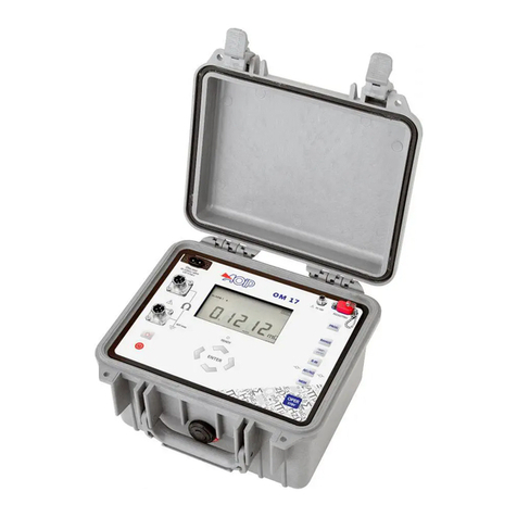
AOIP OM 17 User manual

AOIP

AOIP OM 17 User manual

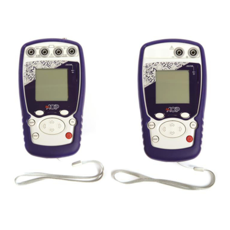
AOIP TC6621 User manual

AOIP

AOIP TC6621 User manual

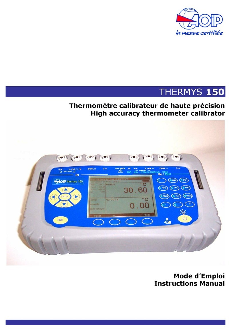
AOIP THERMYS 150 User manual

AOIP

AOIP THERMYS 150 User manual

Popular Measuring Instrument manuals by other brands

Norsonic nor145 User's setup guide

Norsonic

Norsonic nor145 User's setup guide

QEO FFM 100 user manual

QEO

QEO FFM 100 user manual

Hanna Instruments Combo Grochek HI 991404 user manual

Hanna Instruments

Hanna Instruments Combo Grochek HI 991404 user manual

Sekonic SPEEDMASTER L-858D Startup guide

Sekonic

Sekonic SPEEDMASTER L-858D Startup guide

Olympus Vanta L Series Getting started guide

Olympus

Olympus Vanta L Series Getting started guide

WEG MMW03-M22CH user manual

WEG

WEG MMW03-M22CH user manual

ABB ScreenMaster RVG200 Service instruction

ABB

ABB ScreenMaster RVG200 Service instruction

Chauvin Arnox CA832 user manual

Chauvin Arnox

Chauvin Arnox CA832 user manual

gfm Peakanalyzer installation manual

gfm

gfm Peakanalyzer installation manual

PKP DB51 instruction manual

PKP

PKP DB51 instruction manual

Endress+Hauser PROMAG 33 operating manual

Endress+Hauser

Endress+Hauser PROMAG 33 operating manual

ITRON Bluetooth RF Master user guide

ITRON

ITRON Bluetooth RF Master user guide

Sper scientific 860041 instruction manual

Sper scientific

Sper scientific 860041 instruction manual

Rohde & Schwarz ETL 2112.0004.13 Getting started

Rohde & Schwarz

Rohde & Schwarz ETL 2112.0004.13 Getting started

PHYWE Cobra SMARTsense operating instructions

PHYWE

PHYWE Cobra SMARTsense operating instructions

ADA INSTRUMENTS WHEEL 100 DIGITAL operating manual

ADA INSTRUMENTS

ADA INSTRUMENTS WHEEL 100 DIGITAL operating manual

LaserLiner RangeXtender 40 quick start guide

LaserLiner

LaserLiner RangeXtender 40 quick start guide

Kobold DF H 3K Series operating instructions

Kobold

Kobold DF H 3K Series operating instructions

manuals.online logo
manuals.online logoBrands
  • About & Mission
  • Contact us
  • Privacy Policy
  • Terms and Conditions

Copyright 2025 Manuals.Online. All Rights Reserved.