AOpen MX3W-E3 Datasheet

MIC-In
Line-In
Speaker Out
CPU Fan
PS/2 Keyboard
Connector USB Port
SPP/EPP/ECP
Parallel Port
COM 1 Port VGA Connector
MIDI/Game Port
JP28 Keyboard/Mouse Wake-up
Enable/Disable Jumper
Low ESR Condensers
RJ-45 LAN
Connecto
r
COM2 Port Connector
A
UX Fan Connecto
r
DVO Connector
A
TX Power Connector
Intel®810E Chipset for MX3W-E3
Or 810 Chi
p
set for MX3W-V3
168-pin DIMM Socket x2 support
maximum memory size up to 512MB
RAM Power LED
JP23 FSB Select Jumper
FDD Connector
A
TA/100 IDE Connector x2
CD-IN Connecto
r
370-pin CPU Socket with
Frequency/Voltage Auto-detection that
supports Intel®Pentium®III and Celeron™
processors (including Coppermine and
Tualatin) 533MHz~1GHz+ CPU
AUX-IN Connecto
r
MODEM-CN Connecto
r
Onboard AC97 CODEC Chip
IrDA Connecto
r
CNR Expansion Slot
32-bit PCI Expansion Slot x3
WOM (Wake on Modem) Connecto
r
WOL (Wake on LAN) Connecto
r
GPO Connecto
r
Front Panel Audio Connecto
r
2nd USB Port Connecto
r
JP14 CMOS Clear Jumpe
r
Front Panel Connecto
r
4Mbit Flash ROM BIOS
Chassis Fan Connecto
r
System Power LED
JP13 LAN Enable/Disable Select
Jumper (Optional)

Pin 1
1. JP14 Clear CMOS
2. JP28 Enable/Disable Keyboard/Mouse Wake-up Function
Everything you need to boot this
motherboard is included in this
Easy Installation Guide. For more
information, a complete Online
User's Manual can be found in the
Bonus Pack CD Disc. Thanks for
the help of saving our earth.
PART NO: 49.88110.101 DOC. NO: MX3WE3-EG-E0112B
Floppy Cable x 1
80-Wire IDE Cable x 1
Bonus Pack CD disc x 1
This Easy Installation Guide x 1
This motherboard provides keyboard/mouse wake-up function. You can use the JP28 to enable or disable
this function. Please note that both USB and PS types of keyboard and mouse are supported in this
function.
You can clear CMOS to restore system default setting. To
clear the CMOS, follow the procedure below.
1. Turn off the system and unplug the AC power.
2. Remove ATX power cable from connector PWR2.
3. Locate JP14 and short pins 2-3 for a few seconds.
4. Return JP14 to its normal setting by shorting pin 1 & pin 2.
5. Connect ATX power cable back to connector PWR2.
Tip: When should I Clear CMOS?
1. Boot fail because of overclocking…
2. Forget password…
3. Troubleshooting…
Normal Operation
(
Default
)
Clear CMOS
Pin 1
Enable
(Default)
Disable
11
11

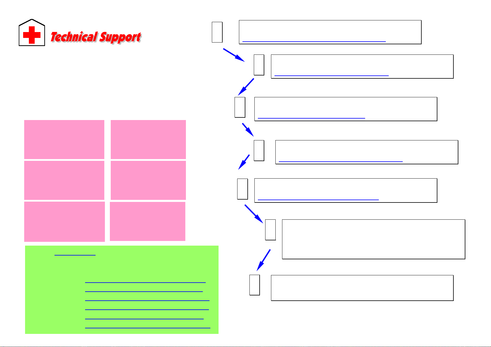
1. Pull up the CPU socket lever and up to
90-degree angle.
2. Locate Pin 1 in the socket and look for a
(golden) cut edge on the CPU upper interface.
Match Pin 1 and cut edge. Then insert the
CPU into the socket.
3. Press down the CPU socket lever and finish
CPU installation.
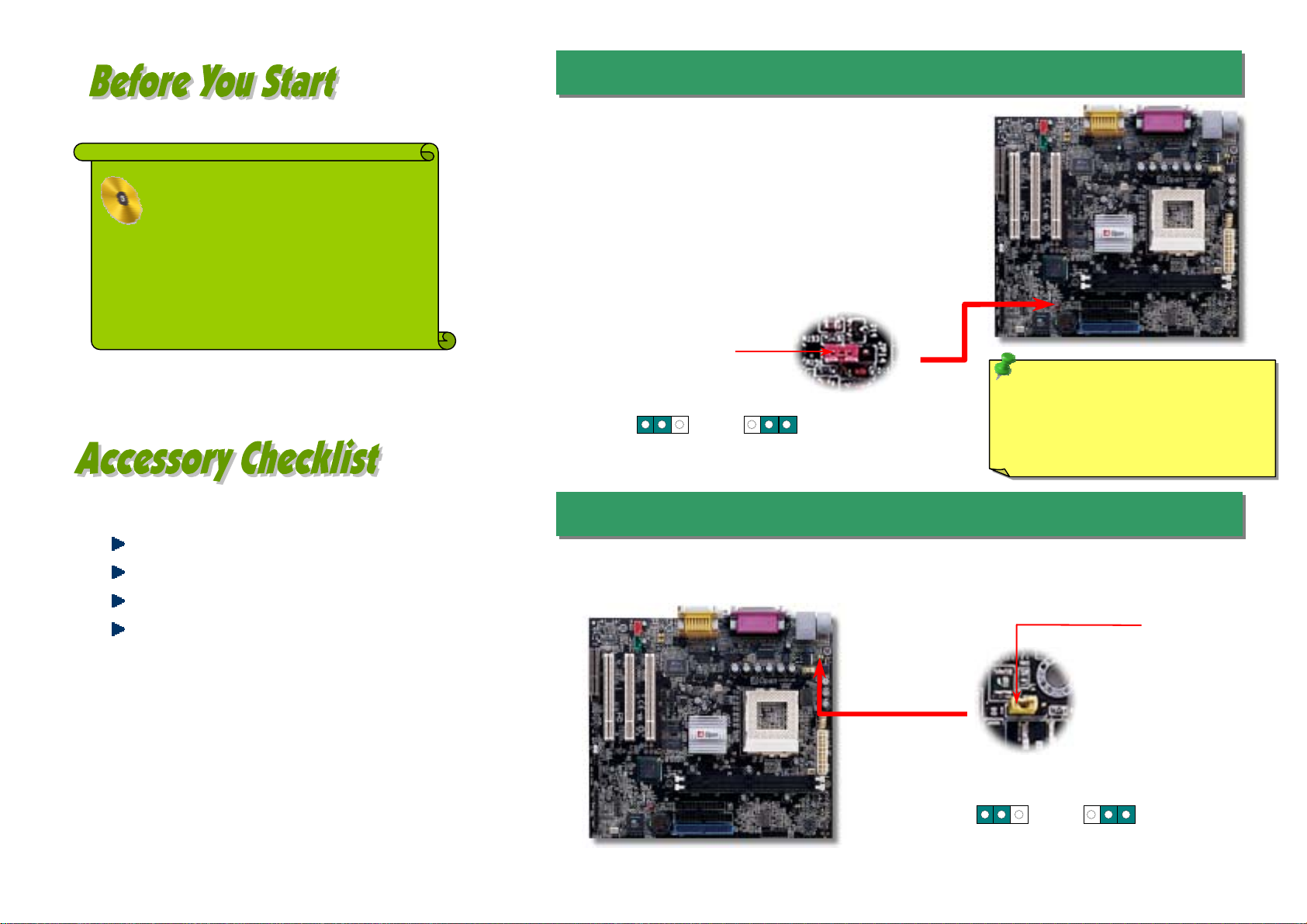
Plug in the CPU fan cable to the 3-pin CPU FAN connector. If you have chassis fan,
you can also plug it on FAN2 or FAN3 (without H/W monitoring) connector.
5. Setting CPU Voltage & Frequency
4. Installing CPU & Housing Fan
3. Installing CPU
Note: If you do not match the CPU
socket Pin 1 and CPU cut edge well,
you may damage the CPU.
CPU socket lever
CPU Pin 1 and cut edge
GND
Note: Some CPU fans do not have
sensor pin, therefore they don’t
support fan monitoring.
CPU Fan Connector
FAN3 Connector
Setting CPU Core Voltage
This motherboard supports CPU VID function. The CPU core voltage will be automatically
detected and the range is from 1.3V to 3.5V. It is not necessary to set CPU Core Voltage.
Setting CPU Frequency
This motherboard is CPU jumper-less design, you can set CPU frequency through the
BIOS setup, and no jumpers or switches are needed.
Core Frequency = CPU FSB Clock * CPU Ratio
CPU Ratio 1.5x, 2x, 2.5x, 3x, 3.5x, 4x, 4.5x, 5x, 5.5x, 6x, 6.5x, 7x, 7.5x, and 8x
CPU FSB 66~133MHz
CPU CPU Core Frequency FSB Clock Ratio
Celeron 533 533MHz 66MHz 8x
Celeron 566 566MHz 66MHz 8.5x
Celeron 600 600MHz 66MHz 9x
Celeron 667 667MHz 66MHz 10x
Celeron 700 700MHz 66MHz 10.5x
Celeron 766 766MHz 66MHz 11.5x
Celeron 800 800MHz 100MHz 8x
Celeron 900 900MHz 100MHz 9x
Celeron 1G 1GHz 100MHz 10x
Celeon 1.1G 1.1GHz 100MHz 11x
Celeron 1.2G 1.2GHz 100MHz 12x
Pentium III 800E 800MHz 100MHz 8x
Pentium III 850E 850MHz 100MHz 8.5x
Pentium III 533EB 533MHz 133MHz 4x
Pentium III 600EB 600MHz 133MHz 4.5x
Pentium III 667EB 667MHz 133MHz 5x
Pentium III 733EB 733MHz 133MHz 5.5
Pentium III 800EB 800MHz 133MHz 6x
Pentium III 866EB 866MHz 133MHz 6.5
Pentium III 933EB 933MHz 133MHz 7x
Pentium III 1000EB 1GHz 133MHz 7.5x
Pentium III 1G 1GHz 133MHz 7.5x
Pentium III 1.13G 1.13GHz 133MHz 8.5x
Pentium III 1.2G 1.2GHz 133MHz 9x
Pentium III 1.3G 1.3GHz 133MHz 10x
Tip: If your system hangs or fails to boot
because of overclocking, simply use <Home>
key to restore the default setting (433MHz).
Warning: Intel®810E chipset
supports maximum 133MHz
FSB and 810 chipset
supports maximum100MHz
FSB. Both support 66MHz
A
GP clock. Higher clock
setting may cause serious
system damage.
FAN2 Connector
SENSOR +12V

1
Pin 1
Secondary
Slave (4th)
Primary
Master (1st)
Primary
Slave (2nd)
Secondary
Master (3rd)
7. JP13 LAN Enable/Disable Select Jumper(Optional)
6. JP23 FSB/PCI Clock Ratio 8. Connecting IDE and Floppy Cables
9. Connecting Front Panel Cable
This jumper is used to specify the relationship of PCI and FSB clock. Generally
speaking, if you are not overclockers, we recommend you to set at the default setting.
This motherboard allows you to enable or disable the LAN onboard function by adjusting
the position of yellow cap.
Connect 34-pin floppy cable and 40-pin IDE cable to floppy connector FDD and IDE
connector. The blue connector is IDE1 for clear identification. Be careful of the pin1
orientation. Wrong orientation may cause system damage.
Warning: Higher CPU FSB frequency may be
able to increase CPU speed, but you may damage
the CPU or reduce the CPU lifecycle.
Speaker
IDE LED
+
+
+
SPWR
+
+ACPI & PWR
LED
Reset
1
SPWR
GND
ACPI LED-
GND
ACPILED+
NC
NC
GND
RESET
GND
NC
NC
+5
V
IDE LED
IDE LED
+5
V
+5
V
GND
NC
SPEAKE
R
A
ttach the power LED, speaker, and reset switch connectors
to the corresponding pins. If you enable “Suspend Mode” item
in BIOS Setup, the ACPI & Power LED will keep flashing while
the system is in suspend mode.
Locate the power switch cable from your ATX housing. It is
2-pin female connector from the housing front panel. Plug this
connector to the soft-power switch connector marked SPWR.
Auto (Default) FSB=133MHz
FSB=100MHz FSB=66MHz
1
JP23
ATA 33/66/100 IDE
Connector
FDD Connector
Pin 1
JP23 FSB Select
Jumper
1 1
1
Pin 1
Enable
(Default) Disable
11

The ATX power supply uses 20-pin connector shown below. Make sure you plug in the
right direction.
You can use the autorun menu of Bonus CD disc. Choose the utility and driver and
select model name.
12. Power-on and Load BIOS Setup
13. Aopen Bonus Pack CD
10. Connecting ATX Power Connector
11. Front Audio Connector
If the housing has been design with an audio port on the front panel, you’ll be able to
connect onboard audio to front panel through this connector. By the way, please remove
the jumper cap from the Front Panel Audio Connector before you connect the cable. Do
not remove this yellow jumper cap if housing without an audio port on the front panel.
A
fter you finish the setting of jumpers and connect correct cables. Power on and
enter the BIOS Setup, press <Del> during POST (Power On Self Test). Choose "Load
Setup Defaults" for recommended optimal performance.
Warning: Please avoid of using "Load
Turbo Defaults", unless you are sure
your s
y
stem components (CPU, DRAM,
HDD, etc.) are good enough for turbo
settin
g
.
Pin 1
MIC_IN2
MICBIAS2
FRONT_R
NC
FRONT_L
GND
+5V
RET_R
KEY
RET_L
1 2
9 10
+12V
5VSB
PW-OK
COM
+5V
COM
+5V
COM
+3.3V
+3.3V
+5V
+5V
-5V
COM
COM
COM
PS-ON
COM
-12V
+3.3V
Del

14. Installing LAN Driver (Optional)
15. Installing Onboard AGP Driver 17. BIOS Upgrade
A
Open Easy Flash is an user-friendly flash method. The BIOS binary file and flash
routine are combined together and you simply run a single file to complete the flash
process.
1. Download new BIOS upgrade zipped file from AOpen's web site. For example,
MX3WE3102.ZIP.
2. Run shareware PKUNZIP (http://www.pkware.com) which supports
miscellaneous operation systems to extract the binary BIOS file and the flash
utility. Or Winzip (http://www.winzip.com/) in Windows environment.
3. Save the unzipped file into a bootable floppy disk.
For example, MX3WE3102.BIN & MX3WE3102.EXE
4. Reboot the system to DOS mode without loading any memory handler (such as
EMM386) or device driver. It needs around 520K free memory space.
5. Execute A:> MX3WE3102 and the program will do the rest of it.
DO NOT turn off the power during FLASH PROCESS until you are asked to!!
6. Reboot system and press <Del> to enter BIOS Setup, Choose "Load Setup
Defaults", then “Save & Exit Setup” and finish the BIOS upgrade.
Warning: The upgrade of new BIOS will permanently replace your original BIOS
content after flashing. The original BIOS setting and Win95/Win98 PnP information
will be refreshed and you probably need to re-configure your system.
16. Installing Onboard Sound Driver
This motherboard integrates a total communication solution including 10/100Mb Fast
Ethernet for Office requirement. You can install LAN Driver under Windows95/98,
Windows NT, Windows 2000 & Windows XP by following steps.
Manually adding an Adapter in Windows 95/98/ME/NT4/2000/XP:
LOCATION OF DRIVER: \Driver\Lan\E100BNT5.SYS (NDIS 5.0)
LOCATION OF SETUP FILE: \Driver\Lan\NET82557.INF
1. From the Control Panel, double-click the “Add Hardware” icon.
2. Double-click Other Devices or Network Adapters in the list area.
3. Double-click a PCI Ethernet Controller.
4. Click the Driver tab, then click Update Driver.
5. Click Next at the Update Device Driver Wizard.
6. Select "Display a list of all the drivers..." and click Next.
7. Insert the AOpen Bonus CD and click Have Disk.
8. Enter the appropriate drive for your disk media
(for example: D:\) ,and click OK.
9. Click OK at the Select Device dialog box.
10. The Update Wizard displays the message that it has found
the driver. Click Next.
11. Click Finish and restart your computer when prompted.
Intel 810E and 810 chipsets integrate a 2D/3D graphics accelerator and provides AGP
1X/2X incredible performance to access main memory at over 1GB/s. You can find the
audio driver from the Bonus Pack CD auto-run menu.
This motherboard comes with a Realtek ALC201 AC97 CODEC. You can find the audio
driver from the Bonus Pack CD disc auto-run menu.
Note: If the New
Hardware Found dialog
box does not appear at
startup and you cannot
connect to the network,
check the Device
Manager list to see if the
new adapter is present.
If it is not, please install
the LAN driver manuall
y
.

If you encounter any trouble to boot you system, follow the procedures
accordingly to resolve the problem.
Part Number and Serial Number
The Part Number and Serial number are printed on bar code label. You can find this
bar code label on the outside packing, on ISA/CPU slot or on component side of PCB.
For example:
Model name and BIOS version
MX3W-E3 R1.00 Nov. 03. 2001 AOpen Inc.
A
ward Plug and Play BIOS Extension v1.0A
Copyright © 1998, Award Software, Inc.
Model name and BIOS version can be found on upper left corner of first boot screen
(POST screen). For example:
P/N: 91.88110.201 is part number, S/N: 91949378KN73 is serial number.
MX3W-E3 is model name of motherboard; R1.00 is BIOS version
Make sure if the jumper settings for CPU and DRAMs are correct.
Clear CMOS.
Install the VGA card. Then connect your monitor and keyboard.
The problem was probably caused
by power supply or motherboard
failure. Please contact your reselle
r
or local distributor for repairing.
Perhaps your VGA card or monito
r
is defective.
No
Yes
No
Yes
It is very possible that your keyboard
is defective.
During system rebooting, press Del to enter BIOS Setup. Choose
“Load Setup Default".
The problem should be caused by the
IDE cables or HDD itself.
Re-install Windows 95, Windows 98 or Windows NT.
Yes
Yes
Turn off the power and unplug the AC power cable, then remove all
of the addon cards and cables, including VGA, IDE, FDD, COM1,
COM2 and Printer.
Turn on the power, and check if
the power supply and CPU fan
work properly.
Start
Check if there is display.
Press Ctrl, and Alt key at the
same time, hold them and then
press Del to see if the
s
y
stem reboots.
Turn off the system and
re-connect the IDE cable.
Check if the system can
reboot successfully.
End
No
No
Part No. Serial No.
Part No. Serial No.

Dear Customer,
Thanks for choosing AOpen products. To provide the best and fastest service to
our customer is our first priority. However, we receive numerous emails and
p
hone-calls worldwide everyday, it is very hard for us to serve everyone on time.
We recommend you follow the procedures below and seek help before contact
us. With your help, we can then continue to provide the best quality service to
more customers.
Thanks very much for your understanding!
A
Open Technical Supporting Team
Online Manual: Please check the manual carefully and make sure the
jumper settings and installation procedure are correct.
http://www.aopen.com/tech/download/manual/default.htm
1
1
Test Report: We recommend to choose board/card/device from the
compatibility test reports for assembling your PC.
http://www.aopen.com/tech/report/default.htm
2
2
FAQ: The latest FAQ (Frequently Asked Questions) may contain a
solution to your problem.
http://www.aopen.com/tech/faq/default.htm
5
5
Download Software: Check out this table to get the latest updated
BIOS/utility and drivers.
http://www.aopen.com/tech/download/default.htm
3
3
News Group: Your problem probably had been answered by our support
engineer or professional users on the news group.
http://www.aopen.com/tech/newsgrp/default.htm
4
4
Contact Distributors/Resellers: We sell our products through resellers
and integrators. They should know your system configuration very well and
should be able to solve your problem more efficiently. After all, It is an
important reference for you if next time you want to buy something else
from them.
6
6
Contact Us: Please prepare detail system configuration and error symptom
before contacting us. The part number, serial number and BIOS version
are also very helpful.
7
7
Web Site: www.aopen.com
E-mail: Send us email by going through the contact form below.
English http://www.aopen.com/tech/contact/techusa.htm
Japanese http://www.aopen.co.jp/tech/contact/techjp.htm
Chinese http://www.aopen.com.tw/tech/contact/techtw.htm
German http://www.aopencom.de/tech/contact/techde.htm
French http://france.aopen.com/tech/contact/techfr.htm
Simplified Chinese http://www.aopen.com.cn/tech/contact/techcn.htm
Pacific Rim
A
Open Inc.
Tel: 886-2-3789-5888
Fax: 886-2-3789-5899
A
merica
A
Open America Inc.
Tel: 1-510-498-8928
Fax: 1-408-922-2935
Europe
A
Open Computer b.v.
Tel: 31-73-645-9516
Fax: 31-73-645-9604
Germany
A
Open Computer GmbH.
Tel: 49-2102-157700
Fax: 49-2102-157799
China
艾尔鹏国际上海(股)
有限公司
Tel: 86-21-6225-8622
Fax: 86-21-6225-7926
Japan
A
Open Japan Inc.
Tel: 81-048-290-1800
Fax: 81-048-290-1820
Other manuals for MX3W-E3
1
This manual suits for next models
1
Other AOpen Computer Hardware manuals

AOpen
AOpen AP41 User manual

AOpen
AOpen AP61 User manual

AOpen
AOpen DEV5400 User manual

AOpen
AOpen DEV7610 User manual

AOpen
AOpen MX6E PLUS User manual

AOpen
AOpen Modt nMCP7AUt-V Series User manual

AOpen
AOpen VA1000 Lite2 User manual

AOpen
AOpen FC-PGA User manual

AOpen
AOpen i55HMt-HD User manual

AOpen
AOpen DP5 User manual
Popular Computer Hardware manuals by other brands

DH electronics
DH electronics 96Boards Avenger96 Getting started

Intel
Intel P4000 - REV 001 datasheet

Viking
Viking TMS-12A Application note

Noise Lab
Noise Lab Fourcaster user guide

Phoenix Mecano
Phoenix Mecano HARTMANN ELECTRONIC PXE100A Series user manual

Freescale Semiconductor
Freescale Semiconductor MPC5200B user guide