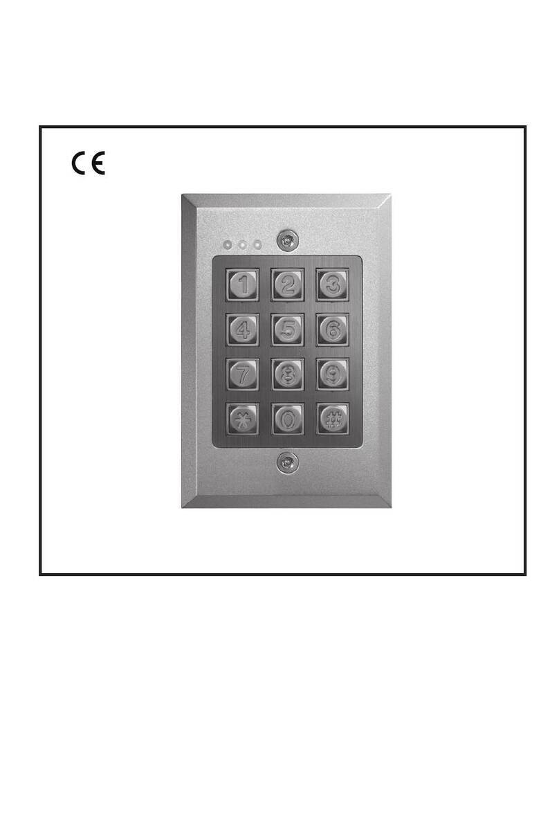
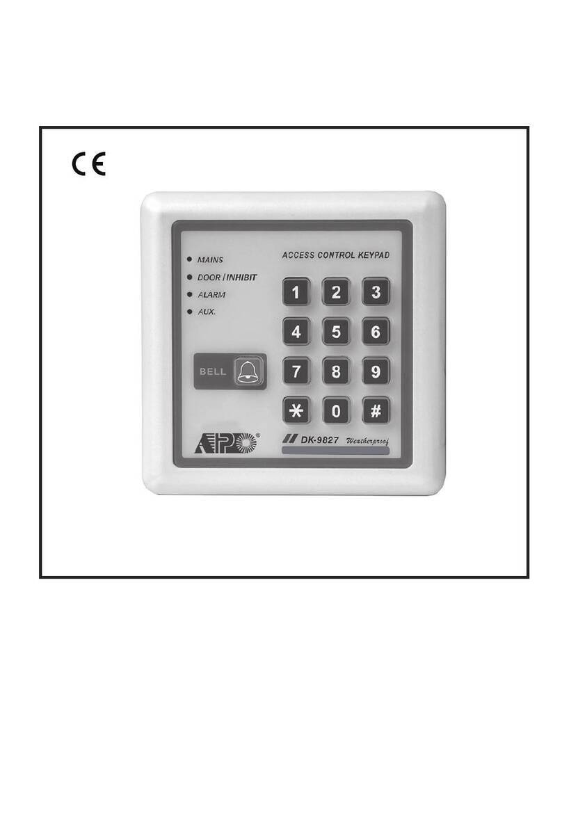
APO DK-9520 MK-II User manual

DIGITAL ACCESS CONTROL KEYPAD
DK-9520 MK-II
Programming & Installation Manual
FOR ELECTRIC LOCK

TABLE OF CONTENTS
INTRODUCTION
DESCRIPTION OF CONNECTION TERMINALS & INDICATORS
STANDARD PROGRAMMING SUMMARY CHART
SETTING & PROGRAMMING
SET KEYPAD TO SINGLE USER MODE (to whom it may require)
SPECIFICATIONS
APPLICATION EXAMPLE
AUXILIARY INFORMATION
······························································································································· 3
······················································ 3-7
················································································································· 4
························································································································· 5
··········································································· 5
·········································································· 6-8
······································································································ 9-26
············································································································· 9
····························································································· 9
············· 9
······························································································ 10
··················································································· 10
······································································································· 11
························································································ 12-13
··································································································· 14
·············································································· 15
········································································ 16-17
·················································································· 18
················································································ 19
······································································································ 20
··················································································· 20
·················································································································· 21
································································································ 21
·········································································································· 22-23
·············································· 24-25
··························································· 24-25
·········································································· 25
······························································································································ 26
················································································································· 27
············································································································· 28
2
INTRODUCTION
DESCRIPTION OF CONNECTION TERMINALS & INDICATORS
eective solutions for residential and commercial installations. It is designed for stand alone electric lock and inter-
lock systems and operates froma12 to 24V AC/DC power supply and virtually compatible with any electric locking
device. Apart from that it is also the perfect choice for controlling security systems, automatic operators and
machinery. The DK-9521 oers single relay output, and that the DK-9522 oers dual relay output.
DK-9521/DK-9522 consists two application softwares of Single User Mode for the general Users, and Multi-User
Mode for the advanced Users. The system oersa4digit length user code with 10,000 combinations for each
output in single user mode; and 100 user codes for output 1 and 10 user codes for output2in length of 4-8 digits
with combinations of more than 100 million in multi-user mode. Operation options of Auto Code entry and Manual
Code entry are available in both two user modes. Programmed information that stored in the system are non-volatile
Normally Closed contact while the keypad is secured on the box. It is open while keypad is separated from the
box. Connect this N.C. terminal to the 24 hour zone of an alarm system if necessary.
Connect to 12-24V AC or DC power supply. The ( ) supply and ( ) GND are the common grounding points of
the keypad system. No selection jumper is required for the full input voltage range.
Connect DC power with the (+) and ( ) polarity indicated; and there is no polarity discrimination for AC power
(POWER INPUT)
- -
CONNECTION TERMINALS
OUTPUT OUTPUT 1
5 Amp relay
5 Amp relay
OUTPUT 2
NPN Open Collector
1 Amp relay
RELAY
1RELAY
2
ON OFF
DAP
+-
12 24V
TAMPER
N.C.
EG
IN
OUTPUT 1
N.C. C. N.O.
TUPTUO 2
.O.N.C.C.N
YEK
.TCA
ROOD
SNES
)(
DNG
-UD
TUO
.TNI
KCOL
1P/O
BIHNI
TAMP
ON OFF
DAP
EG
IN
OUTPUT 1
N.C. C. N.O.
TUPTUO 2
.O.N.C.C.N
YEK
.TCA
ROOD
SNES
)(
DNG
-UD
TUO
.TNI
KCOL
1P/O
BIHNI
DK-9522
R
1 2 3
456
78 9
0#
RED
AMBER
GREEN
DK-9521
INHIBIT
(RED)
MAINS
(AMBER)
DOOR
(GREEN)
3

device. The relay can be programmed in Start/Stop (toggle) mode or timer mode from1to 999 seconds.
2
1 - 2 : TAMPER N.C.
3 - 4 : 12V DC --
6 - 7 : OUTPUT 1 --
Fail-Secure Electric
Lock in Default
8 - EG IN --
●
●
●
●
CONNECTION TERMINALS
4

THE LED INDICATORS
MAINS (AMBER)
DOOR (GREEN)
INHIBIT (RED)
BACK LIGHTING
THE PACIFIER TONES & THE LED INDICATING SIGNALS
NOTE:
*
**
STATUS TONES*LED SIGNALS
1. In programming mode
---
1 Beep
2 Beeps
5 Beeps
Continuous Beeps
---
1 second Long Beep **
ON
1 Flash
2 Flashes
5 Flashes
Continuous Flashes
1 Flash in 2 seconds interval
---
2. Successful key entry
3. Successful code entry
4. Unsuccessful code entry
5. DAP jumper not replaced
6. In standby mode
7. Output relay activated
●
●
●
5

A) Enter Programming Mode with Master Code (Exit-Factory Master Code: 0 0 0 0)
NOTE:
B) System Refreshing –
C) Code Entries –
1) Recording Master Code and User Codes – (No Default Codes)
2) Recording Super User Code – (No Default Codes)
3) Recording the Visitor Codes – (No Default Codes)
(Default: Momentary, 1-second)
STANDARD PROGRAMMING SUMMARY CHART
(default=1 second)
6

(Default: Fail-Secure)
(Default: 10 tries / 30 seconds)
(default)
(Default: 1 long beep)
H) User Code Entry Modes (Auto or Manual) – (Default: Manual)
(Default: ON)
(default)
J) Main LED Flashing ON-OFF – (Default: Flashing)
(default)
(default)
(default)
7

(D) DURESS OUTPUT
K) Egress Delay & Warning – (Default: Instant, No warning)
(default)
L) Exit Programming Mode
8

( ii)Alarm System Arm-Disarm Control
Use the (N.O.) or (N.C.) output contact to make arm-disarm control of an alarm system.
Consult your alarm control panel manual for the appropriate output contact to be used in arm-disarm control.
(i)Shunting an N.C. Zone
Use the Normally Open (N.O.) output contact to shunt a Normally Closed (N.C.) protection zone of an
alarm system.
Set output contact to Start / Stop Mode (Programming Option 51).
(E) OUTPUT 2 (FOR DK-9522 ONLY)
ALARM CONTROL PANEL
24 HOUR N.O.
PROTECTION
ZONE
OR
1.5K
LED
+12V
LOW POWER
PIEZO BUZZER
YEK
.TCA
ROOD
SNES
)(
DNG
-UD
TUO
TNI
COL
1P/O
BIHNI
YEK
.TCA
ROOD
SNES
)(
DNG
-UD
TUO
TNI
COL
1P/O
BIHNI
TUPTUO 2
.O.N.C.C.N
YEK
.TCA
N.C.
N.C. MAGNETIC CONTACT
TO PROTECTION ZONE
OF AN ALARM CONTROL PANEL
OR
TUPTUO 2
.O.N.C.C.N
YEK
.TCA
ALARM CONTROL PANEL
REMOTE
ARM-DISARM
CONTROL
NO. OR N.C.
Criteria for Programming
MUST
DO NOT
Enter and Exit Programming Mode
key.
Master Code
3. Exit the programming mode by pressing the
NOTE:
●
●
●
●
●
SETTING & PROGRAMMING
DAP
ON OFF
9

/ Stop mode (Programming Option 51) for single station systems.
19
New Master Code
NOTE:
●
●
●
Programming Example :
0 0 0 0
2. Program a new Master Code 3 2 8 9 for the keypad:
NOTE:
●3 2 8 9
●
3 2 8 9
2. key to clear all the current stored data
except the Master Code:
NOTE:
●(default)
System Refresh (Complete Data Refresh) (Refresh Code 8901)
10

User ID Entry of Code
Output 1
NOTE:
●
●00-99
●
●
●
Programming Example :
3 2 8 9
2. Program an User Code 8 3 2 1 for output 1 ---------- One of the 100 user codes (user ID: 00-99,
taking ID = 01 as example):
Operaon (Manual Code Entry Mode)
NOTE:
11

Super User Code
NOTE:
●
●
●
●
Programming Example :
3 2 8 9
2. Program 2 5 8 0 as Super User Code:
Operaon :
12

NOTE:
●
●
●This feature is recommended for Fail-safe locks only.
●
REMARK :
is in operation to hold the door lock open, all the User Codes
including Super User Code for Output 1 are temporarily suspended.
3)
NOTE:
●
●
●
13

One-Time
Time-Limit
User ID Entry of Code
NOTE:
●
●0-9
●
●
●
●
Programming Example :
3 2 8 9
2. Program a Visitor Code 1 3 7 8 at ID “0” for One-Time use:
3. Program a Visitor Code 2 3 0 8 9 at ID “1” with Time-Limit of 5 hours:
4. Program a Visitor Code 8 3 5 8 at ID “2” with Time-Limit of 10 hours:
Operaon :
14

Consult your alarm control panel manual for the appropriate output contact to be used in arm-disarm control.
Use the Normally Open (N.O.) output contact to shunt a Normally Closed (N.C.) protection zone of an
Deleng Examples:
3289
a)
b)
c)
15

Time Length
A)
B)
C)
D)
NOTE:
●
Programming Options for Output 1 (See “Programming Summary Chart” Secon D for more informaon) :
Example:
8 3 2 18 3
5 4 3 2 15 4
Example:
5 4 3 2 15 4 3
9 2 7 0 5 39 2 7
16

Operaon :
8 3 2 1
8 3 2 1
8 3 2 1
NOTE:
●The purpose of the accelerated Code --
●
Super User Code
Programming Examples:
3 2 8 9
2. Set Output 1 in momentary mode of 5 seconds:
3. Set Output 1 in Start / Stop Mode:
4. Set Output 1 in Start / Stop Mode with 2-digit Accelerated Start Code:
17

Type of Lock
Programming Codes for Type of Locks:
Important Note to Installer:
de-energized
(Default)
energized
18

Programming Codes for Lock-Up Opons:
(Default)
Super User Code
Programming Examples:
3 2 8 9
19

Programming Opons:
(Default)
Programming Opons:
User Code Entry Modes (Auto or Manual) (Location 82)
(Default)
20
Table of contents
Other APO Keypad manuals

APO
APO DK-9826 MK-II User manual

APO
APO DK-9330 A User manual

APO
APO DK-9827 MK-II User manual

APO
APO DK-9823 MK-II User manual

APO
APO DK-9820 MK-II User manual

APO
APO DK-9522 MK-II User manual

APO
APO DK-9350 User manual

APO
APO DK-9866 MK-II User manual

APO
APO DK-9821 MK-II User manual

APO
APO DK-9865 MK-II User manual
Popular Keypad manuals by other brands

Radio Shack
Radio Shack 49-454 owner's manual

CompuSTAR
CompuSTAR RF-2WG15R-FM Quick start card

Honeywell
Honeywell 6271C - Ademco TouchCenter Color Keypad Installation and user guide

SILENTRON
SILENTRON 5528 KEYPAD HT quick start guide

CAMDEN
CAMDEN CV-634PR installation instructions

DSC
DSC PC500 instruction manual