TABLE OF CONTENTS
INTRODUCTION
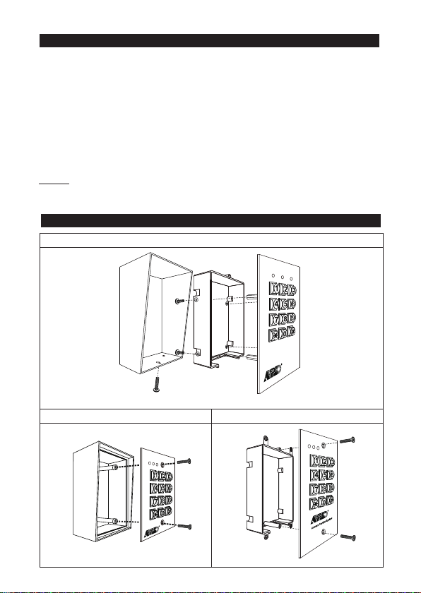
ASSEMBLY
DESCRIPTION OF CONNECTION TERMINALS & INDICATORS
STANDARD PROGRAMMING SUMMARY CHART
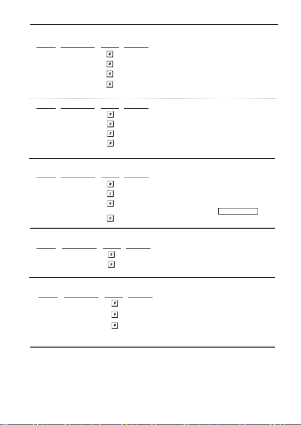
SETTING & PROGRAMMING
SET KEYPAD TO SINGLE USER MODE (to whom it may require)
SPECIFICATIONS
APPLICATION EXAMPLE
APPLICATION HINTS FOR THE AUXILIARY FACILITIES
AUXILIARY INFORMATION
······························································································································· 3
········································································································································ 3
······················································ 4-6
················································································································· 4-6
························································································································· 7
·································································································································· 7
··········································································· 7
·········································································· 8-10
······································································································ 11-26
············································································································· 11
····························································································· 11
············· 11
······························································································ 12
··················································································· 12
······································································································· 13
························································································ 14-15
·································································································· 16
··································································································· 17
·············································································· 18
································································· 19-20
················································································ 21
··························································································· 22
······································································································ 22
··················································································· 23
·················································································································· 23
································································································ 23
·········································································································· 24-25
·········································································· 25
············································· 26-27
··························································· 26-27
·········································································· 27
······························································································································ 28
············································································································ 29-31
······························································ 32-34
············································································································· 35
2