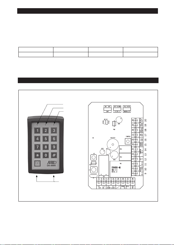
1 - 2 : 12V DC --
3 - 4 : OUTPUT 1 --
Fail-Secure Electric
Lock in Default
6 - 7 : DOOR BELL
8 - EG IN --
9 - 10 - 11 : OUTPUT 2
12 : OUTPUT 3
13 - 14 : TAMPER N.C.
15 : DOOR SENS --
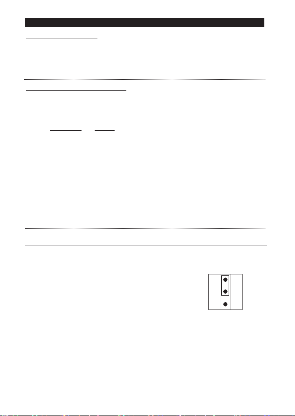
NOTE:
1) Door Auto Re-lock
2) Door Forced Open Alarm and Warning
3) Door Propped-up Warning
4) Inter-lock Control
16 : GND (–) --
17 : DU OUT --
18 : O/P 1 INHIB. --
19 : INT. LOCK
●
●
●
●
●
5