AQC MAXAIR User manual

Owner’s manual for installation,
use and maintenance
This manual is property of the owner. Leave with the unit when set-up and start-up are complete.
AQC Dust Collecng Systems inc. reserves the right to change design and specicaons without prior noce.

Fume Arms
2
Fume Arms
2
INDEX
1 Introducon ................................................. 3
2 InformaonontheMAXAIRfumearm............................ 3
3 Presentaon ................................................. 4
3.1 Each MAXAIR unit includes ....................................... 4
4 Modelnumbers .............................................. 5
4.1 Hanging or table / bench mount................................... 5
4.2 Telescopic fume arm ............................................ 5
5 Normaluse .................................................. 6
6 Operaonandpurpose ........................................ 6
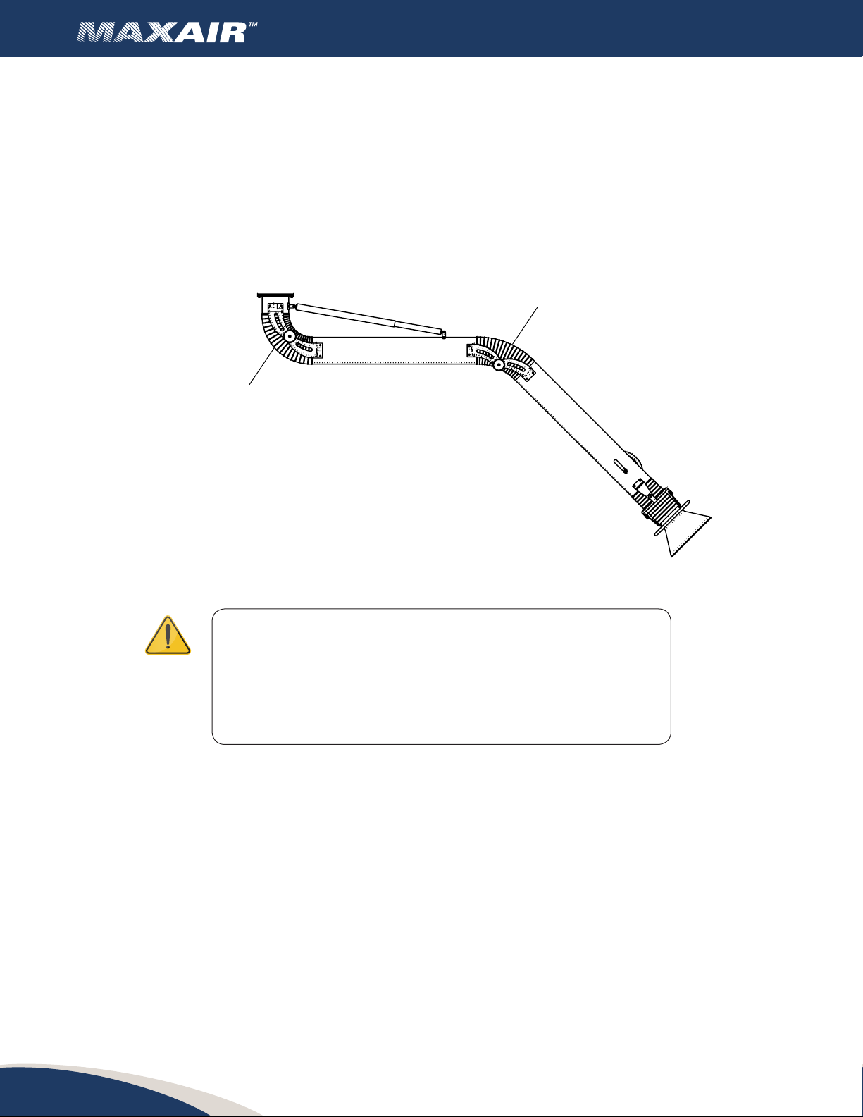
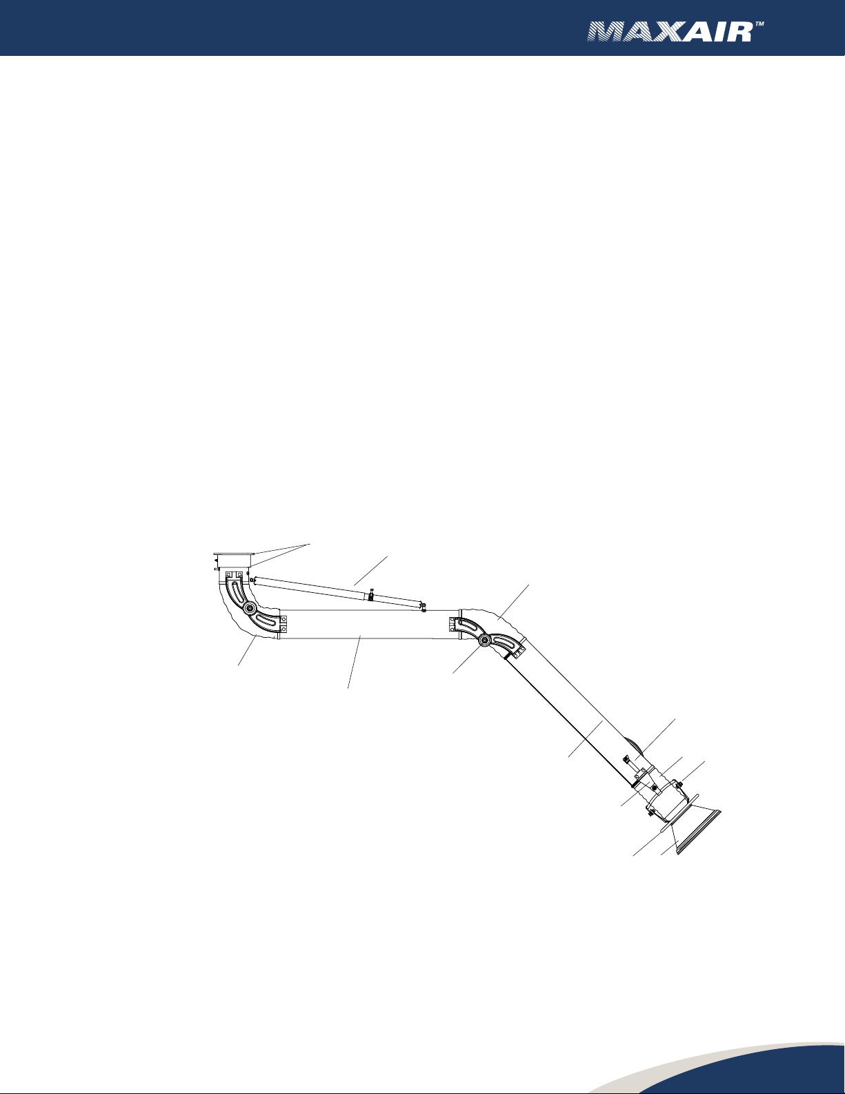
7 Components ................................................. 7
7.1 MAXAIR main components (hanging version) ........................ 7
7.2 MAXAIR main components (bench mount / portable version) .......... 8
7.3 MAXAIR main components (telescopic version) ...................... 9
8 Installaon .................................................. 10
8.1 Inspeconofgoods ............................................. 10
8.2 Locaon....................................................... 10
8.3 Armandwall/postbracketinstallaon
(hanging type, no exhaust fan) .................................... 11
8.4 Armandceilingbracketinstallaon(hangingtype) ................... 13
8.5 Armandbracketinstallaon(hangingtypewithexhaustfan) .......... 14
9 Oponalequipment........................................... 15
9.1 MAXAIRtypicalinstallaons...................................... 15
10 Start up ..................................................... 18
10.1 Check list ..................................................... 18
11 Lightkitpartslistandinstallaon................................ 18
12 Electricalconnecons.......................................... 19
12.1 MAXAIR single phase fan starter (without light kit) ................... 19
12.2 MAXAIR three phase fan starter (without light kit).................... 19
12.3 MAXAIR single phase fan starter (with light kit) ...................... 20
12.4 MAXAIR three phase fan starter (with light kit)....................... 20
13 Maintenanceandinspecon ................................... 21
14 Troubleshoong .............................................. 22
15 Warranty.................................................... 23
16 Limitaonofliability .......................................... 24
17 Applicability ................................................. 24
18 Governinglaw ............................................... 24

Fume Arms
3
1 INTRODUCTION
This present manual refers to the MAXAIR source capture fume arm. It includes important
informaonconcerningtheinstallaon,useandmaintenanceofyourunit.Readthismanual
thoroughly and apply the direcves and procedures. Sta and personnel using the system
shouldbetrainedonsafetymeasuresandmaintenanceinstrucons.
2 INFORMATIONONTHEMAXAIRFUMEARM
Model: Serial number:
Delivery date: Date of installaon:
Name of customer:
Address:
Accessories:
Other:
WARNING!
Theuseofthefumearmwillrequireproperinstallaon
and handling. Contact AQC Inc. if you have any doubt in
regard to the use of your fume arm.
Notfollowingdirecvesandprocedurescouldcause
injuriesorpropertydamages.
Fume Arms
3

Fume Arms
4
3 PRESENTATION
TheMAXAIRfumearmisasystemdesignedtobeposionedneartheareawherefume,smoke,
dustoranypollutantisbeingproduced.Thefumearm(alsosomemescalledsnorkel)isan
eecvesystemtoremoveharmfulpollutantsfromtheworker’sbreathingzone.
MAXAIR capture arms are not a guarantee that all the fumes or smoke will be captured in the
seconhood.Hoodposionningisimportanttousurecollecon.
Mainapplicaonsincludewelding,bung,pharmaceucaloperaons,handlingofvolaledusts,
harmful vapours, etc.
TheMAXAIRfumearmoersmulpleconguraonsforsourcecapture.Oponalequipmentmay
includeadirectdrivefan,extensionswingboomforaddionalreach,slidingrailwithtrolley,etc.
3.1 EachMAXAIRunitincludes:
• External and adjustable joints
• Paintedsteelorstainlesssteeltubesforminimalstacpressureloss
• Flexible hoses at the joints
• Capturehoodswithdeectorsformaximuminletvelocity(deectordeletedon3"arm)
• Shut-oairdamperwithadjustablehandle
• Pivongsocket
• Jointwheelathoodseconforfull360degreesposioning
• Grabhandleathoodseconforsourcecaptureposioning
• Companionangeforductconnecon(withhangingmodelonly)
• Fasteners (nuts, washers, bolts)
TheMAXAIRfumearmunitisshippedfullyassembledwiththeexceponoftherecoilspring(not
necessaryon3"diameterarmsandportable/benchmountversions).Thespringassemblyrequires
minimalaachmenttothearmsocketbracket.

Fume Arms
5
4 MODELNUMBERS
4.1 Hangingortable/benchmount
4.2 Telescopicfumearm
Models Armdiameter
in / mm
Armmin.
length
in / mm
Armmax.
length
in / mm
Standard
hood
diameter
in / mm
Oponal
hood
diameter
in / mm
Weight
lbs / kg
FA-TPGG4-06 4 / 102 52 / 1321 72 / 1829 8 / 203 - 19 / 8,6
FA-TPGG5-06 5 / 127 52 / 1321 72 / 1829 10 / 254 15 / 381 30 / 13.6
FA-TPGG6-06 6 / 152 52 / 1321 72 / 1829 13 / 330 20 / 508 36 / 16.3
Hanging Bench
mount
Stainless
steel
hanging
Stainless
steel
bench
mount
Arm
diameter
in / mm
Armlength
/ m
Standard
hood
diameter
in / mm
Oponal
hood
diameter
in / mm
Weight
lbs / kg
FA-HPG3-03 FA-PPG3-03 FA-HSS3-03 FA-PSS3-03 3 / 76 3 / 1.0 7 / 178 –14 / 6.4
FA-HPG3-05 FA-PPG3-05 FA-HSS3-05 FA-PSS3-03 3 / 76 5 / 1.5 7 / 178 –16 / 7.3
FA-HPG4-05 FA-PPG4-05 FA-HSS4-05 FA-PSS4-05 4 / 102 5 / 1.5 8 / 203 –17 / 7.7
FA-HPG4-07 FA-PPG4-07 FA-HSS4-07 FA-PSS4-07 4 / 102 7 / 2.1 8 / 203 –19 / 8.6
FA-HPG4-08 FA-PPG4-08 FA-HSS4-08 FA-PSS4-08 4 / 102 8.5 / 2.4 8 / 203 –22 / 10
FA-HPG5-07 FA-PPG5-07 FA-HSS5-07 FA-PSS5-07 5 / 127 7 / 2.1 10 / 254 15 / 381 38 / 17.2
FA-HPG5-10 FA-PPG5-10 FA-HSS5-10 FA-PSS5-10 5 / 127 10 / 3.0 10 / 254 15 / 381 43 / 19.5
FA-HPG5-14 FA-PPG5-14 FA-HSS5-14 FA-PSS5-14 5 / 127 14 / 4.3 10 / 254 15 / 381 47 / 21.3
FA-HPG6-07 FA-PPG6-07 FA-HSS6-07 FA-PSS6-07 6 / 152 7 / 2.1 13 / 330 20 / 508 44 / 20
FA-HPG6-10 FA-PPG6-10 FA-HSS6-10 FA-PSS6-10 6 / 152 10 / 3.0 13 / 330 20 / 508 52 / 23.6
FA-HPG6-14 FA-PPG6-14 FA-HSS6-14 FA-PSS6-14 6 / 152 14 / 4.3 13 / 330 20 / 508 60 / 27.2
FA-HPG8-07 FA-PPG8-07 FA-HSS8-07 FA-PSS8-07 8 / 203 7 / 2.1 13 / 330 20 / 508 57 / 25.9
FA-HPG8-10 FA-PPG8-10 FA-HSS8-10 FA-PSS8-10 8 / 203 10 / 3.0 13 / 330 20 / 508 66 / 29.9
FA-HPG8-14 FA-PPG8-14 FA-HSS8-14 FA-PSS8-14 8 / 203 14 / 4.3 13 / 330 20 / 508 74 / 33.6

Fume Arms
6
WARNING!
MAXAIR3"and4"fumearmshavepinchpoints
at top and middle joints. DONOTPLACEFINGERS
ORHANDSATPINCHPOINTSWHENMOVING
THEARMINTODESIREDPOSITION.
5 NORMALUSE
The MAXAIR fume arm is designed to remove dust and smoke from the air resulng from a
manufacturingprocess.EachMAXAIRfumearmisbuiltasperthecriteriaandinformaonsupplied
bythecustomerforaspecicapplicaonandshouldnotserveanyotherapplicaonwithoutthe
approval of AQC inc.
6 OPERATIONANDPURPOSE
Duringnormaloperaon,theMAXAIRfumearmispulledorpushedintoposionnearthesourceof
pollutants(8"to16"fromthesource).Thehoodtubegrabhandle(on5",6"and8"armsonly)may
beusedforlateralorvercalposioningandthehoodcirculargrabhandleallowsfull360degrees
rotaon.Thevacuumfan(opon)drawspollutantswithinthearmandareexhaustedoutside
(whenpermied)orlteredbymeansofanoponaldustcollector(refertoOSHAregulaons
concerningairltraonandrecirculaon).Inordertomaximizevacuumofharmfulpollutants,the
integrateddampershouldbeshutowhenthearmisnotinusewithmulplearminstallaonon
a single exhaust fan.
PINCH POINT
PINCH POINT

Fume Arms
7
2
3
4
98
6
5
7
2
2
10
11
1
7 COMPONENTS
7.1 MAXAIRmaincomponents(hangingversion)
1. Socketsetassembly
2. Flexible hose (typ. of 3)
3. Sockettube
4. Hood tube
5. Damper handle
6. Connectors for hood movement (typ. of 4)
7. Joint wheel
8. Capture hood
9. Hood grab handle
10. Arculangjoints(typ.of8)
11. Telescopicrecoilspringassemblywithspringstopper(excepton3"arms)

Fume Arms
8
7.2 MAXAIRmaincomponents(benchmount/portableversion)
1. Socketsetassembly
2. Flexible hose (typ. of 3)
3. Sockettube
4. Hood tube
5. Damper handle
6. Connectors for hood movement (typ. of 4)
7. Joint wheel
8. Capture hood
9. Hood grab handle
10. Arculangjoints(typ.of8)
1
2
2
2
34
5
67
8
9
10

Fume Arms
9
7.3 MAXAIRmaincomponents(telescopicversion)
1. Socketsetassembly
2. Flexible hose (typ. of 2)
3. Sockettube(xed)
4. Hood tube (sliding, twist and lock)
5. Damper handle
6. Connectors for hood movement (typ. of 4)
7. Joint wheel
8. Hood grab handle
9. Arculangjoints(typ.of4)
10. Telescopicrecoilspringassemblywithspringstopper(excepon4"arms)
1
2
2
3
4
5
6
78
9

Fume Arms
10
8 INSTALLATION
The MAXAIR fume arm is designed to remove dust and smoke from the air resulng from a
manufacturingprocess.EachMAXAIRfumearmisbuiltasperthecriteriaandinformaonsupplied
bythecustomerforaspecicapplicaonandshouldnotserveanyotherapplicaonwithoutthe
approval of AQC inc.
WARNING!
Installaonofequipmentmustbeperformedasperlocal
buildinglawsandregulaons.Structuremustmeetproper
weight support of arm and equipment.
Wall support must be securely bolted
to the wall, see page 15.
8.1 Inspeconofgoods
The MAXAIR fume arm is shipped assembled except for the spring assembly (when needed).
Proceedwithavisualinspeconuponreceivingthematerialandcheckforanyapparentdamage
that may have happened during freight. Generally, shipment includes the fume arm and support
bracket(inarmboxandifordered).Otheroponalcomponentssuchexhaustfansandextension
booms may be included with shipment.
Inspect box or crate appearance when receiving the goods. Report damages to carrier immediately.
Failure to do so will void future claims.
Note :Becauseofsizesanddimensions,oponaloversizedhoodsmaybeshippednotaachedto
hoodjointassembly.Minimaleldassemblywillberequired.
8.2 Locaon
1. The area where the fume arm will be installed should be able to sustain the weight of such
alongwiththeaccessories,ducng,fanoranyoponalequipment.
2. Installer should ensure area around the fume arm will be free of obstacles such as beams,
lighngxtures,overhead cranes,etc.
3. Heightofinstallaonforfumearmbracket(hangingversion)shouldbeasshowninchart
below.
4. Forsafetymeasures,aminimumtwo(2)mancrewshouldbeappointedfortheinstallaon.
5. Fumearmmayalsobeductmounted.Ifso,ducngmustbeabletosupportweightofarm
combinedwithpushandpulleectsofmovingthearmforsourcecaptureposon.
6. TheMAXAIRfumearmmayalsobeusedwithoponalAQCequipmentsuchasextension
swingbooms,slidingrailwithtrolley,portableltraonunits,etc. Refer to appropriate
manualforinstallaon.

Fume Arms
A
Armlength
/ m
B
Maximumreach
at45”(1143mm)
ooor / m
C
Maximumreach
at45”(1143mm)
ooor / m
D
Maximumreach
at45”(1143mm)
ooor / m
E
Recommended
mounngheight
/ m
3 / 0.9 2.6 / 0.8 3 / 0.9 5.2 / 1.6 6 / 1.8
5 / 1.5 3.5 / 1.1 5 / 1,5 7 / 2.1 6 / 1.8
7 / 2.1 5.5 / 1.7 7 / 2.1 11 / 3.4 6 / 1.8
8.5 / 2.4 7.4 / 2.3 7 / 2.1 14.8 / 4.5 7 / 2.1
10 / 3 8.5 / 2.6 7.8 / 2.4 17 / 5.2 8 / 2.4
14 / 4.3 11.2 / 3.4 10.2 / 3.1 22.4 / 6.8 8 / 2.4
COMPANION
DUCT FLANGE
DUCT
FLANGE
11
8.3 Armandwall/postbracketinstallaon(hangingtype,
noexhaustfan)
Theinstallaoncrewmustensurethearm/bracketassemblyisinstalled
within the arm reach of the area where source capture has to be
performed. The arm bracket must be installed on a wall, post or any
otherstructurecapableofsupporngweightofthearmandoponal
equipment.
Note on arms equipped with recoil telescopic springs :Donotaach
springassemblyfromsockettubespringbrackettorotangsocketbefore
step # 4 is completed.
1. Install bracket on support structure at proper height for arm length.
Fasteners to support structure are not supplied. Arm bracket can
alsobeweldedtostructureifallowedorpermied.
2. The duct ange is inserted from underneath the arm support
bracket into the bracket outlet. The fume arm socket will hold the
ductangeintoposion.
Note before installing 5" 6" and 8" diameter fume arms : The
rotangarmsockethasastopperwhichconsistsofasocketset
screwboltedonthemalepartofthesocketanda"tooth"onthe
femalepartblockingthearmfromdoingafull360degreesrotaon.
If the arm bracket is installed on a wall or a column, ensure the
"tooth"isfacingthewallorthecolumn.3"and4"armsareableto
rotate360degreesanddonothaveastopper.
3. LiMAXAIRfumearmintoposionandalignbotharmandbracket
boltpaerns.
4. Using the fasteners provided, aach the arm onto the support
bracket.Ensuretheductangeiscenteredwiththebracketoultet.
Beforeproceedingtothenextstep,pushthearmleandthenright
to ensure the socket rotates freely.
Donotremovespringtubestopper.

Fume Arms
12
WARNING!
DONOTOVERTIGHTEN.
THISCOULDCAUSEFRICTIONDISKFAILURE.
6. Armjointsarepartlyadjustedatthefactoryandwillneednaladjustmentpriortousage.
Usingtwo(2)adjustablewrenches,ghtenalljointsstarngfromthetopleandtopright.
Onewrenchwillholdthenyloninsertlocknotandtheotherwrenchwillholdtheheadof
thebolt.Beginwithonlyhalfturnsalternangleandrightunlarmholdsit’sposionand
does not sag.
Proceedwithleandrightmiddlejoints.Endwithallfour(4)adjustablejointsathood
secon.
7. Move arm UP/DOWN/LEFT/RIGHTtoensurearmstaysinposion.
8. Proceedwithducnginstallaontoductangeortoexhaustfan.
5. Toaachthespringtelescopicassembly,pushthearmUPunltheeyeletonthespring
assembly meets with the male socket spring bracket. Insert eyelet in spring bracket and
aachwithfastenersprovided.
SOCKET JOINTS
ADJUSTMENT
MIDDLE JOINTS
ADJUSTMENT
HOOD JOINTS
ADJUSTMENT
TUBE TO AT TACH SPRING ASSEMBLY
AT TACH
SPRING HERE
TUBE TO AT TACH SPRING ASSEMBLY
AT TACH
SPRING HERE
TUBE TO AT TACH SPRING ASSEMBLY
AT TACH
SPRING HERE
LIFT TUBE TO ATTACH SPRING ASSEMBLY
ATTACH SPRING HERE
SPRING STOPPER

Fume Arms
13
8.4 Armandceilingbracketinstallaon(hangingtype)
Theinstallaoncrewmustensurethearm/bracketassemblyisinstalledwithinthearmreachfor
the area where source capture has to be performed. The arm bracket must be installed to ceiling
trussesorjoistsoranyotherstructurecapableofsupporngweightofthearmand oponal
equipment.
1. Install bracket on support structure according to arm length. Fasteners to support structure
arenotsupplied.Armbracketcanalsobeweldedtostructureifallowedorpermied.
Proceedwithsteps3to7inarmhangingtypeinstallaonprocedures.
8.5 Armandbracketinstallaon(hangingtypewithexhaustfan)
Note :Thistypeofinstallaonwillnotrequiretheductange.
Theinstallaoncrewmustensurethearm/bracketassemblyisinstalledwithinthearmreachof
the area where source capture has to be performed. The arm bracket must be installed on a wall,
postoranyotherstructurecapableofsupporngweightofthearmandoponalequipment.
Note on arms equipped with recoil telescopic springs : Donotaachspringassemblyfromsocket
tubespringbrackettorotangsocket.
WARNING!
Theelectricalconneconmustbeperformedbyaqualied
electricianandwithrespecttocodesandregulaons.
Forsafetymeasures,shutopowersupplytothemotor
prior to perform repairs.

Fume Arms
14
COMPANION
DUCTFLANGE
Note on arms equipped with recoil telescopic springs : Donotaachspringassemblyfromsocket
tubespringbrackettorotangsocketbeforestep#4iscompleted.
1. Install bracket on support structure according to arm length. Fasteners to support structure
arenotsupplied.Armbracketcanalsobeweldedtostructureifallowedorpermied.
2. TheMAXIDRIVEexhaustfanshouldbefacingright,leorfront.Refertobuildingowner
orengineerfordireconofexhaustair.Placefanontoarmsupportbracket.Alignfaninlet
angeboltholestoboltpaernonarmbracket.Securefantemporarilytosupportbracket
using C clamps.
Proceedwithsteps3to7inarmhangingtypeinstallaonprocedures.
3. Connect exhaust ductwork (and silencer if supplied) to fan outlet.
9 OPTIONALEQUIPMENT
TheMAXAIRfumearmisoeredwithoponsasfollows:
1. Direct mount exhaust fan
2. LED 24V light kit with switch
3. 24V hood mounted fan switch
4. 24 V transformer for light or fan switch
5. Oversizedhoods(shippedunassembledtofumearm)
6. Hood screen mesh
7. 304or316stainlesssteeltubesandhoods
8. Aluminum arm tubes
9. PVC tubes (not available in all diameters)

Fume Arms
15
FUME ARM
SUPPORT BRACKET
9.1 MAXAIRtypicalinstallaons.
Otherinstallaonsarepossible.ContactAQCoryourrepresentavefordetails.
MAXAIR (hanging model, wall or post)
with bracket only.
MAXAIR (portable or table/bench
mount) with bracket.
Note on bench mount models : Do not force arm down at socket past the maximum bend. This
may cause damages in the spring and cable assembly in socket.
9.1.1 Mounng
The capture arm can be mounted on a wall. Ensure the wall is level, and use the holes of the
mounngbrackettomarktheholes.
Uselockingxingboltsandnutssuitableforthewallmaterialandifthewallisnotsolid,aplate
should be installed on the opposite side to sandwich the wall and provide a solid support.
SUPPORT BRACKET
FUME ARM
53" MIN.

Fume Arms
16
HORIZONTAL BEAM
FUME ARM
FUME ARM
FAN
MAXIREACH
CEILING BRACKET
FUME ARM
EXHAUST DUCTWORK
CONNECTION
SILENCER
EXHAUST FAN
FUME ARM
Note : aangedreducer
will be required if bracket
and arm are not of same
diameters.ex:1hp6"
faninletwith5"diameter
fume arm
MAXAIR (hanging model, wall or post)
with exhaust fan and support bracket.
MAXAIR (hanging model)
withhorizontalxedextensionbracket.
MAXAIR (hanging model)
with ceiling bracket.
MAXAIR (hanging model) with
MAXIREACH extension swing boom,
MAXIDRIVE exhaust fan and silencer

Fume Arms
17
FAN SUPPORT
BRACKET
FAN
MAXIREACH-BD
DUCTWORK
RAIL
SLIDING
TROLLEY
FUME ARM
VERTICAL FLOOR
POST
SPACER (IF NECESSARY)
SUPPLIED BY OTHER FUME ARM
FUME ARM
EXHAUST DUCTWORK
CONNECTION
6
7
4
1
3
3
2
5
No
QTÉ
Description
1 1
Bride à douille
2 1
Anneau central UHMW noir
3 2
Anneau extérieur UHMW noir
4 1
Bague inférieure (letée)
5 1
Bague supérieure (non letée)
6 2
Boulon 0.25 x 0.75"
7 1
Support de ressort de douille (2 trous)
MAXAIR (hanging model, wall or post)
with exhaust fan and support bracket.
MAXAIR (hanging model, wall or post)
with exhaust fan and support bracket.
MAXAIR (hanging model)
withvercaloorpost
MAXAIRpivongsocketconguraonfor
4",5",6"and8"diameterswithTeon
typeOringsfor360°rotaon.
6
7
4
1
3
3
2
5
No
QTY
Description
1 1
Socket ange
2 1
Middle ring UHMW black
3 2
Exterior ring UHMW black
4 1
Lower ring (threaded)
5 1
Upper ring (unthreaded)
6 2
Bolt 0.25 x 0.75"
7 1
Socket spring bracket (2 holes)

Fume Arms
18
screws
10 STARTUP
10.1 Checklist
Priortousingthefumearmfortherstme,thechecklist
mustbefollowedtoensureaproperconnuousoperaon.
1. Ensurearmmovesfreelyandstaysinesiredposion.
2. Ensure arm is bolted correctly to support bracket
3. Openandclosearmdampertomakesureitoperates
properly
4. Movearmleandrighttoensureitdoesnothitpostsor
walls
5. Move arm up to make sure it does not hit lights or ceiling.
6. Ensure all ductwork is sealed and installed properly.
7. If arm is supplied with MAXIDRIVE exhaust fan, start
fan for only 5 seconds and listen for grinding or unusual
noise. If fan runs smoothly, you may start using the
system.RefertoMAXIDRIVEinstruconmanualifyou
needinstrucons.
11 LIGHTKITPARTSLISTANDINSTALLATION
Note : Light kit and fan switch operate on 24 A.C. 25' (7.7
meters) of low voltage cable is supplied.
Light kits and fan switches are factory installed on the fume
armhoodswhenorderedwithsuch.Fieldinstallaonisalso
possible.AQCwillsupplyinstruconprocedureiflightkitorfan
switch is ordered once the fume arm is installed.
1. Wire set
2. LED light 24VAC/35W
3. O-ringseal
4. Protecveglass
5. Mounngplate
6. Bolts
7. Control switches (fan and light)
8. Hood
9. Wire seal
10. Shield
11. Light kit dome
Note : If light blinks, ensure wiring and bulb screws
areghtened.
1
7
81011
9
23
45
6

Fume Arms
19
12 ELECTRICALCONNECTIONS
TheelectricalconnecondiagramsshownbelowarethemostcommonsuppliedbyAQCSpecial
orcustomizedpanelsareavailable.Contactyourrepresenvefordetails.
12.1 MAXAIRsinglephasefanstarter(withoutlightkit)
12.2 MAXAIRthreephasefanstarter(withoutlightkit)
Westburne (Laval)
3409 Boul. Industriel
(450) 663-5333
Laval, Qc, H7L 4S3
Aireau Qualite Controle
STARTER
POWER, 3 PHASES
24V CONTROL
DATE: 2010-02-17
660 Rue de la Sablière
Bois-des-Fillions, Qc, J6Z 4T7
(450) 621-66612010-02-17DATE:
REV:
A22.1
2016-05-10
CLIENT 1 :
01/06
CLIENT 2 :
PAGE:
DESSINÉ PAR :
VÉRIFIÉ PAR :
IMPRIMER :
2315, Rue Sigouin
J2C 6T4
Drummondville, Qc
819.475.2255
0123456789
A
B
C
D
E
F
G
H
I
J
L3
L2
L1 T1
T2
T3
L1
L3
SUPPLY
VAC
3 PH 60 HZ
OL
CF
MOTOR
OL
95 96
START / STOP
MOTOR
A1
CF
A2
BLACK
WHITE
L2
T1
MECHANICAL RESET
ON
POWER
WHITE
GREY
ASSEMBLER WIRING
ELECTRICIAN WIRING
CF
ORANGE
CF
YELLOW
RED
OL
BROWN
MTR1
OPTION
CLASS 2
OPTION
SXX
OPTION FXX
Adjust according to the table 1: VOLT
Adjust according to the table 1: OL
Adjust according to the table 2 or 3
X1
X2
H1
H2
40VA
21
3 4
6
24VAC
5
U1
V1
W1
L1 L2
Westburne (Laval)
3409 Boul. Industriel
(450) 663-5333
Laval, Qc, H7L 4S3
Aireau Qualite Controle
STARTER
660 Rue de la Sablière
Bois-des-Fillions, Qc, J6Z 4T7
(450) 621-6661
DATE: 2010-02-17
2010-02-17DATE:
POWER, 1 PHASE
WITHOUT TRANSFORMER
REV:
2016-05-10A22.1
CLIENT 1 :
03/06
CLIENT 2 :
PAGE:
DESSINÉ PAR :
VÉRIFIÉ PAR :
IMPRIMER :
2315, Rue Sigouin
J2C 6T4
Drummondville, Qc
819.475.2255
0123456789
A
B
C
D
E
F
G
H
I
J
L3
L2
L1 T1
T2
T3
L1
L2 / N
SUPPLY
VAC
1 PH 60 HZ
OL
CF
OL
MOTOR
95 96
START / STOP
MOTOR
A1
CF
A2
BLACK
WHITE
MECHANICAL RESET
ON
POWER
WHITE
GREY
CF
ASSEMBLER WIRING
ELECTRICIAN WIRING
CF
ORANGE
YELLOW
OL
RED
BROWN
MTR1
OPTION
1 A
Adjust according to the table 1: VOLT
SXX
OPTION
OPTION FXX
Adjust according to the table 1: OL
FU
Adjust according to the table 2 or 3
21
3 4
65
U1
V1
L1 L2

Fume Arms
20
12.3 MAXAIRsinglephasefanstarter(withlightkit)
12.4 MAXAIRthreephasefanstarter(withlightkit)
Westburne (Laval)
3409 Boul. Industriel
(450) 663-5333
Laval, Qc, H7L 4S3
Aireau Qualite Controle
STARTER
POWER, 1 PHASE
24V CONTROL
DATE: 2010-02-17
2010-02-17
660 Rue de la Sablière
Bois-des-Fillions, Qc, J6Z 4T7
(450) 621-6661DATE:
REV:
A22.1
2016-05-10
CLIENT 1 :
02/06
CLIENT 2 :
PAGE:
DESSINÉ PAR :
VÉRIFIÉ PAR :
IMPRIMER :
2315, Rue Sigouin
J2C 6T4
Drummondville, Qc
819.475.2255
0123456789
A
B
C
D
E
F
G
H
I
J
L3
L2
L1 T1
T2
T3
L1
L2 / N
SUPPLY
VAC
1 PH 60 HZ
OL
CF
OL
MOTOR
95 96
START / STOP
MOTOR
A1
CF
A2
BLACK
WHITE
T1
ON
MECHANICAL RESET
POWER
WHITE
GREY
ASSEMBLER WIRING
ELECTRICIAN WIRING
CF
CF
ORANGE
YELLOW
RED
OL
BROWN
OPTION
MTR1
CLASS 2
Adjust according to the table 1: VOLT
OPTION
SXX
OPTION FXX
Adjust according to the table 1: OL
Adjust according to the table 2 or 3
X1
X2
H1
H2
40VA
21
3 4
6
24VAC
5
U1
V1
L1 L2
Westburne (Laval)
3409 Boul. Industriel
(450) 663-5333
Laval, Qc, H7L 4S3
Aireau Qualite Controle
STARTER
POWER, 3 PHASES
24V CONTROL
DATE: 2010-02-17
660 Rue de la Sablière
Bois-des-Fillions, Qc, J6Z 4T7
(450) 621-66612010-02-17DATE:
REV:
A22.1
2016-05-10
CLIENT 1 :
01/06
CLIENT 2 :
PAGE:
DESSINÉ PAR :
VÉRIFIÉ PAR :
IMPRIMER :
2315, Rue Sigouin
J2C 6T4
Drummondville, Qc
819.475.2255
0123456789
A
B
C
D
E
F
G
H
I
J
L3
L2
L1 T1
T2
T3
L1
L3
SUPPLY
VAC
3 PH 60 HZ
OL
CF
MOTOR
OL
95 96
START / STOP
MOTOR
A1
CF
A2
BLACK
WHITE
L2
T1
MECHANICAL RESET
ON
POWER
WHITE
GREY
ASSEMBLER WIRING
ELECTRICIAN WIRING
CF
ORANGE
CF
YELLOW
RED
OL
BROWN
MTR1
OPTION
CLASS 2
OPTION
SXX
OPTION FXX
Adjust according to the table 1: VOLT
Adjust according to the table 1: OL
Adjust according to the table 2 or 3
X1
X2
H1
H2
40VA
21
3 4
6
24VAC
5
U1
V1
W1
L1 L2
Table of contents
Other AQC Industrial Equipment manuals