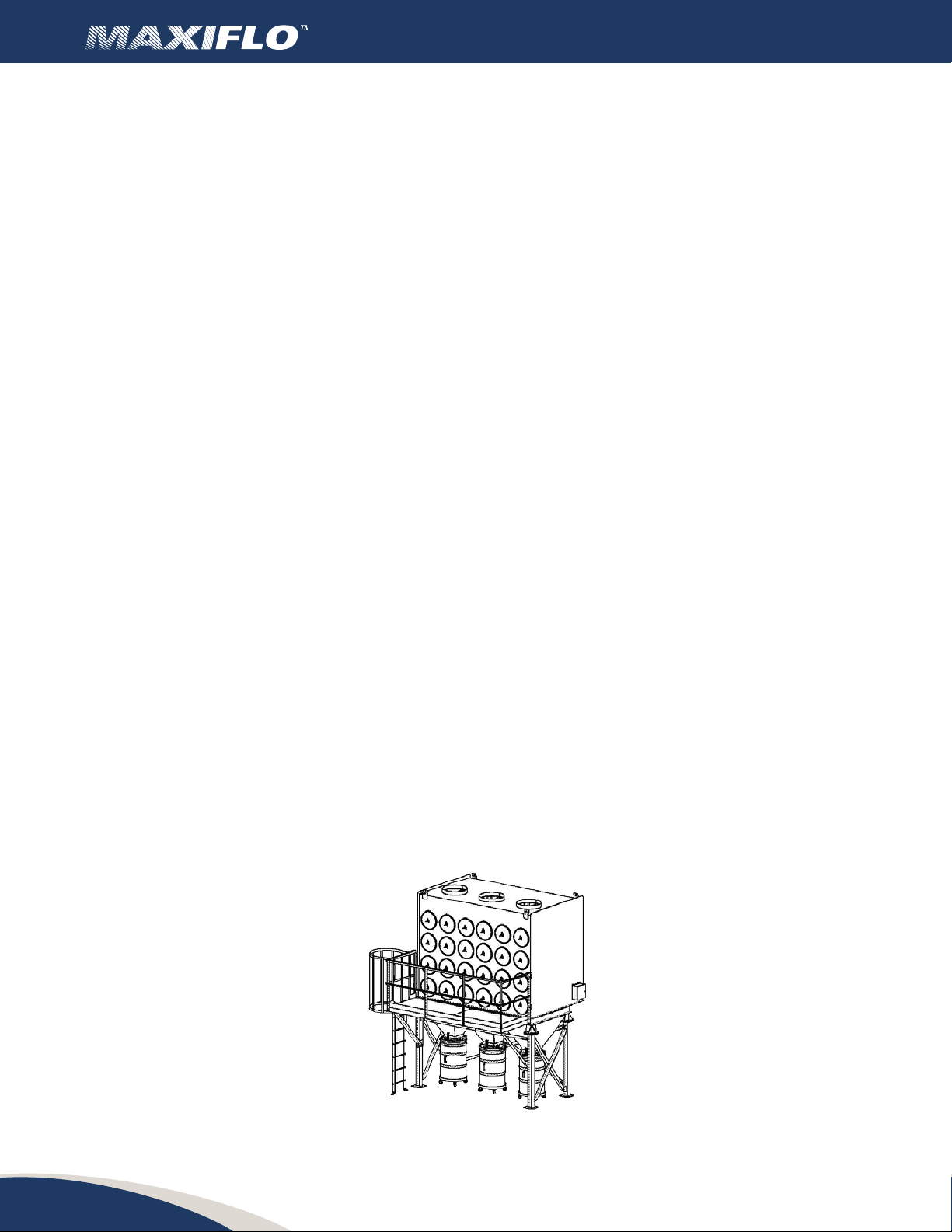
Horizontal downow pleated cartridge dust collector
22
INDEX
1 Introducon ................................................. 3
2 Informaononthedustcollector ................................ 3
3 Presentaon ................................................. 4
3.1 Each MAXIFLO unit includes ...................................... 4
4 Normaluse .................................................. 4
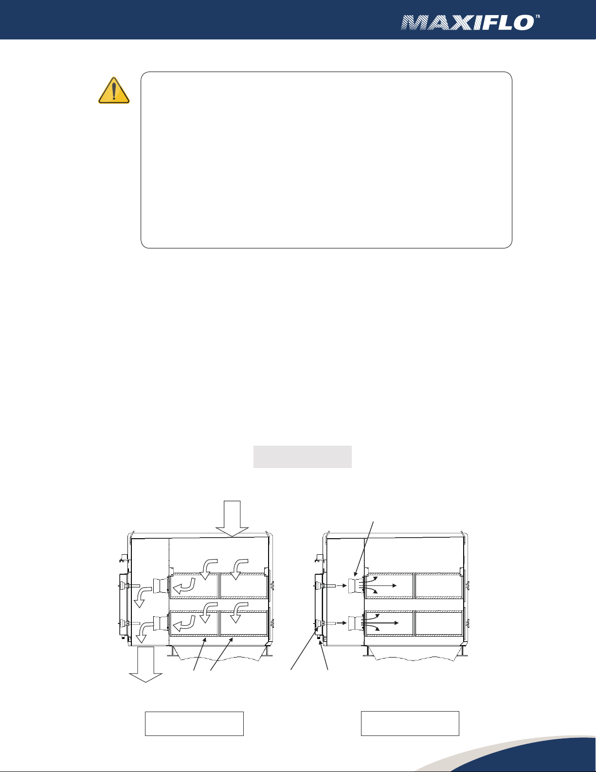
5 Operaon ................................................... 5
5.1 Cartridge cleaning .............................................. 5
6 Installaon .................................................. 6
6.1 Inspeconofgoods ............................................. 6
6.2 Locaon....................................................... 6
7 Assembly ................................................... 7
7.1 Requiredtools ................................................. 7
8 Assembly.................................................... 7
9 Structureassembly............................................ 8
10 Electricalconnecon .......................................... 10
10.1 ElectricalconneconforDCT-500sequencer ........................ 10
10.2 ElectricalconneconforDCT-1000sequencer ...................... 11
10.3 Compressedairconnecon....................................... 13
10.4 Venlaonducng.............................................. 13
11 Start up ..................................................... 13
11.1 Check list ...................................................... 13
12 Electricalconnecons ......................................... 14
12.1 Check list ...................................................... 14
12.2 Electricalconnecons ........................................... 14
12.3 Oponalequipment............................................. 14
12.4 An-abrasiveinlet .............................................. 15
12.5 Plaormandladder ............................................. 16
12.4 Explosionreliefvent............................................. 16
13 Magnehelicgauge ............................................ 17
14 Start/Stopprocedure .......................................... 17
14.1 Startupwithnewlters ......................................... 17
14.2 Regular start up ................................................ 17
14.3 Shutdown .................................................... 17
15 Safety ...................................................... 17
15.1 Sta-Workers .................................................. 17
15.2 Electricalcomponents ........................................... 18
15.3 Explosivedusts ................................................. 18
15.4 Anchors ...................................................... 18
15.5 Interiorinstallaon ............................................. 18
15.6 Sparkproducingacvies ........................................ 18
16 Maintenance................................................. 19
16.1 Remplacementofcartridges...................................... 19
16.2 Remplacementofcartridges...................................... 19
17 Compressedairsystem ........................................ 21
17.1 Explosionvent ................................................. 21
17.2 Controlpanel .................................................. 21
18 Programminginstrucons ...................................... 22
18.1 DCT-500sequencer ............................................. 22
18.2 DCT-1000sequencer ............................................ 22
19 Maintenanceandinspecon ................................... 23
20 Troubleshoong .............................................. 24
21 Warranty .................................................... 27
22 Limitaonofliability .......................................... 28
23 Applicability ................................................. 28
24 Governinglaw ............................................... 28