manuals.online logo
Brands
  1. Home
  2. •
  3. Brands
  4. •
  5. Aquadart
  6. •
  7. Bathroom Fixture
  8. •
  9. Aquadart wetroom 10 User manual

Aquadart wetroom 10 User manual

This manual suits for next models

10

Other Aquadart Bathroom Fixture manuals
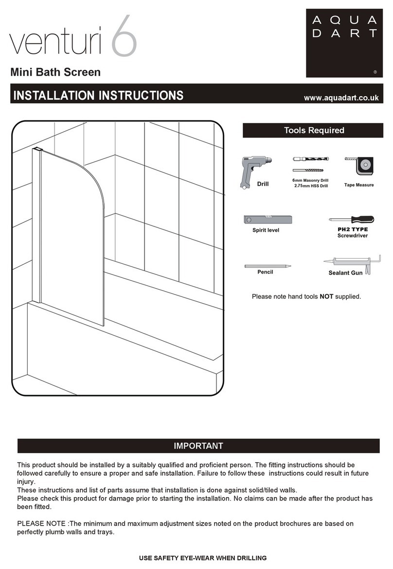
Aquadart Venturi 6 AP9575 User manual

Aquadart

Aquadart Venturi 6 AP9575 User manual
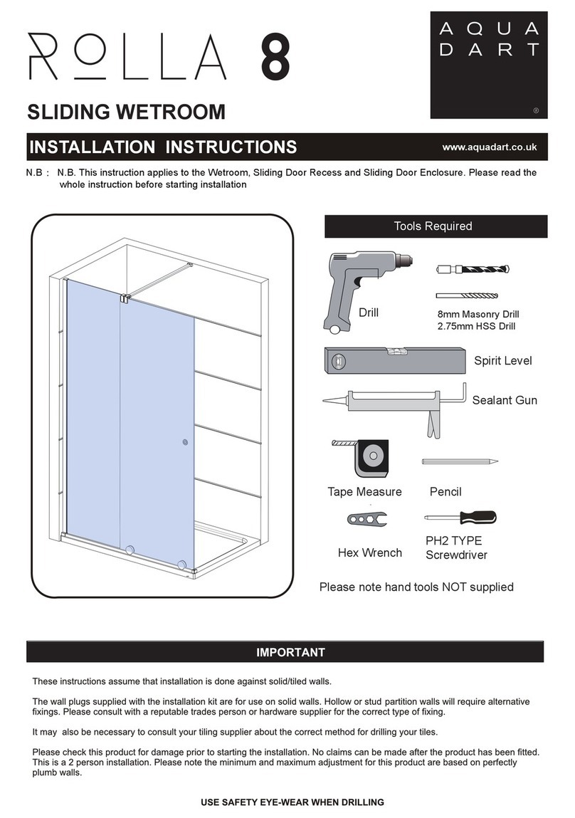
Aquadart Rolla 8 User manual

Aquadart

Aquadart Rolla 8 User manual
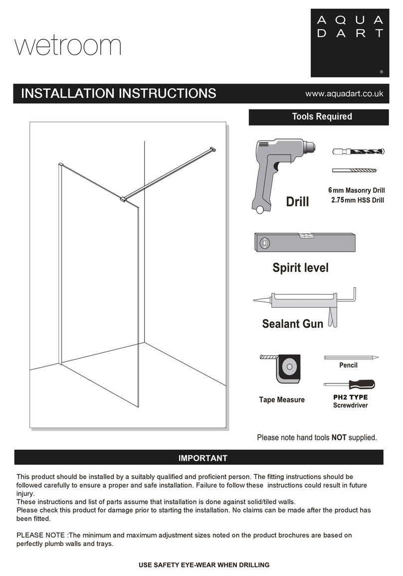
Aquadart wetroom 8 User manual

Aquadart

Aquadart wetroom 8 User manual
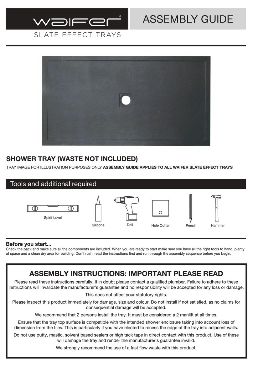
Aquadart waifer Aqualavo User manual

Aquadart

Aquadart waifer Aqualavo User manual
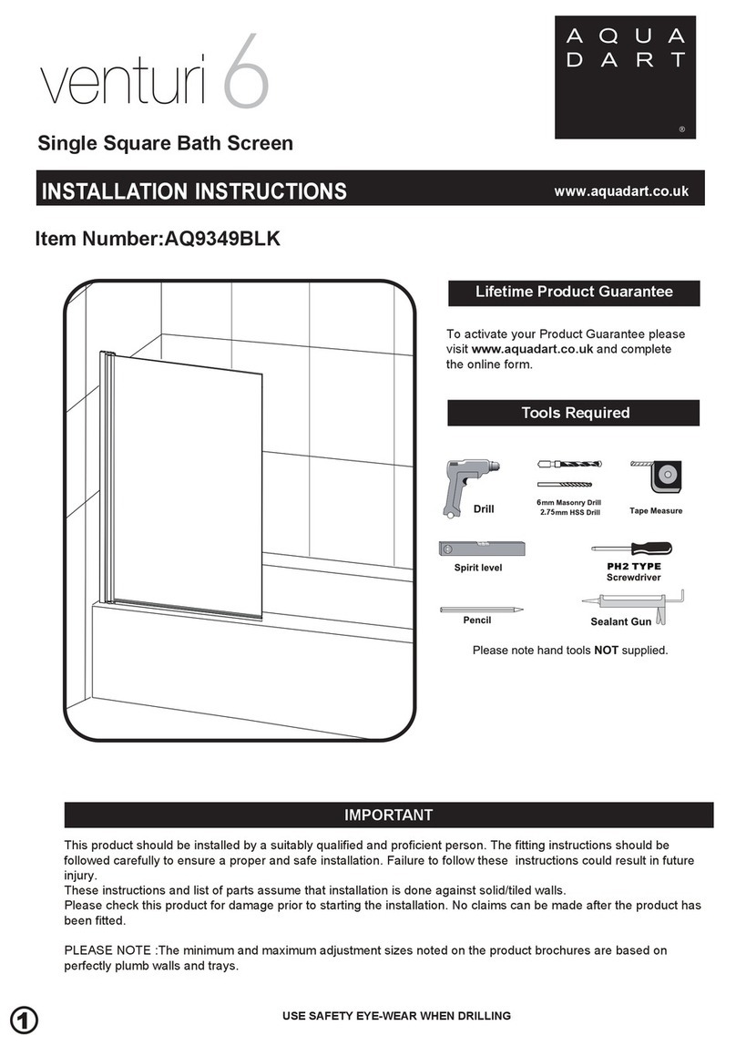
Aquadart venturi 6 AQ9349BLK User manual
Aquadart

Aquadart venturi 6 AQ9349BLK User manual

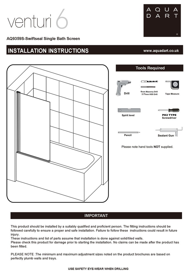
Aquadart venturi 6 AQ9359S User manual

Aquadart

Aquadart venturi 6 AQ9359S User manual

Aquadart venturi 8 AQ6002 User manual

Aquadart

Aquadart venturi 8 AQ6002 User manual

Aquadart venturi 6 AQ9357LS User manual
Aquadart

Aquadart venturi 6 AQ9357LS User manual

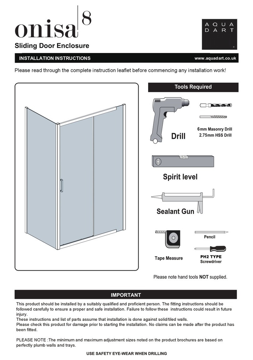
Aquadart onisa8 User manual

Aquadart

Aquadart onisa8 User manual
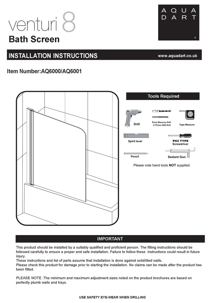
Aquadart Venturi 8 User manual

Aquadart

Aquadart Venturi 8 User manual

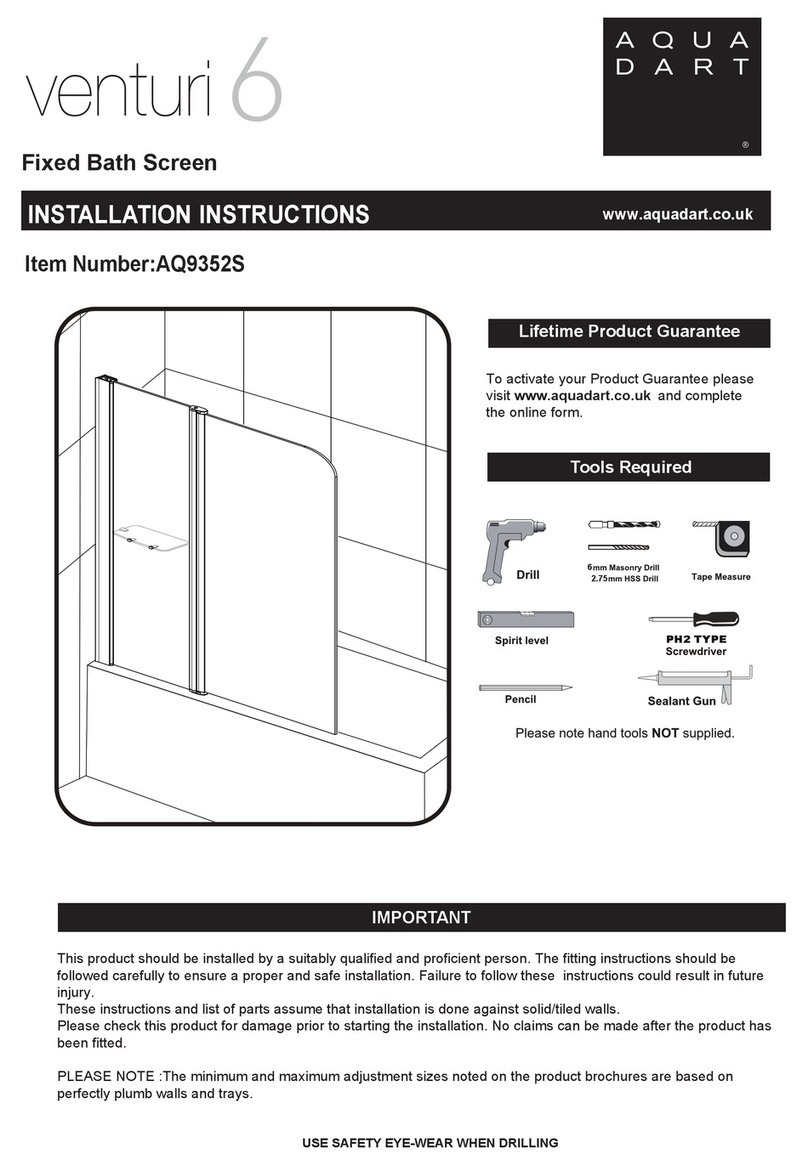
Aquadart Venturi 6 AQ9352S User manual

Aquadart

Aquadart Venturi 6 AQ9352S User manual

Popular Bathroom Fixture manuals by other brands

Kohler Mira Sport Max J03G Installation and user guide

Kohler

Kohler Mira Sport Max J03G Installation and user guide

Moen 186117 Series installation guide

Moen

Moen 186117 Series installation guide

Hans Grohe Raindance Showerpipe 27235000 Instructions for use/assembly instructions

Hans Grohe

Hans Grohe Raindance Showerpipe 27235000 Instructions for use/assembly instructions

Signature Hardware ROUND SWIVEL BODY SPRAY 948942 Install

Signature Hardware

Signature Hardware ROUND SWIVEL BODY SPRAY 948942 Install

fine fixtures AC3TH installation manual

fine fixtures

fine fixtures AC3TH installation manual

LIXIL HP50 Series quick start guide

LIXIL

LIXIL HP50 Series quick start guide
KOLO ATOL PLUS installation manual

KOLO

KOLO ATOL PLUS installation manual

Hans Grohe PuraVida 15073000 Instructions for use/assembly instructions

Hans Grohe

Hans Grohe PuraVida 15073000 Instructions for use/assembly instructions

Toto TS111B8 Installation and owner's manual

Toto

Toto TS111B8 Installation and owner's manual

Kohler K-1158-H2 Homeowner's guide

Kohler

Kohler K-1158-H2 Homeowner's guide

Coram Showers OFFSET QUADRANT manual

Coram Showers

Coram Showers OFFSET QUADRANT manual

baliv DU-2010 manual

baliv

baliv DU-2010 manual

odass OD-1710 instruction manual

odass

odass OD-1710 instruction manual

Oxygenics Evolution Easy installation instructions

Oxygenics

Oxygenics Evolution Easy installation instructions

Bradley Express SS Series installation instructions

Bradley

Bradley Express SS Series installation instructions

Helvex TH-974 installation guide

Helvex

Helvex TH-974 installation guide

DURAVIT C.1 C15240 0090 Instructions for mounting and use

DURAVIT

DURAVIT C.1 C15240 0090 Instructions for mounting and use

Sunshower PURE SOLO manual

Sunshower

Sunshower PURE SOLO manual

manuals.online logo
manuals.online logoBrands
  • About & Mission
  • Contact us
  • Privacy Policy
  • Terms and Conditions

Copyright 2025 Manuals.Online. All Rights Reserved.

10MM WETROOM
IMPORT ANT EYE-WEAR WHEN DRILLING
6
PH2 TYPE
2.75
Tools Required
Please read through the complete instruction leaflet before commencing any installation work.
US E S AF E TY E Y E -WE AR W HE N DR IL L ING
INST ALLA TION INSTRUCTIONS www.aquadart.co.uk
This product should be installed by a suitably qualified and proficient person. The fitting instructions should be
followed carefully to ensure a proper and safe installation. Failure to follow these instructions could result in future
injury.
These instructions and list of parts assume that installation is done against solid/tiled walls.
Please check this product for damage prior to starting the installation. No claims can be made after the product has
been fitted.
PLEASE NOTE :The minimum and maximum adjustment sizes noted on the product brochures are based on
perfectly plumb walls and trays.
Description
1
Box Contents
COMPONENTS AND BOX CONTENTS
NO.Qty
11
1
5
1
4
2
3
4
5
Description
2
3
4
5
6
7
1
14
13
12
11
Seal
1
6
1
7
NO.Qty
81
1
1
1
2
9
10
11
12
1
13
14
9
Cover Cap (Wall Profile)
Wall Profile
Wall Plugs
Fixed Panel
Screws 4x30 Pan Head
Drip Strip
Drip Strip End Cap
10
Vertical
Seal
Fixed
Panel
Moving Door
Hinge
Bottom seal
Wall Bracket Screws 4x30 Pan Head
Optional Return Panel
8
Wall Plugs
2.0mm
2.5mm
4.0mm
x 1
Please check this product for missing components prior to installation.
IMPORTANT - Missing Components
For spare parts visit
2. The tiles or other wall finishing should be effectively sealed at tray edges.
3. Tiles should extend at least to the corner of the tray and a minimum of 2.0 meters from the top of the tray.
FIXING KIT COMPONENTS, SITE CONDITIONS
FIXING KIT
4x30mm
x4
x4 x1 x1
x1
4x30mm
x1
Allen Key
x1
Screws
Wall Bracket
Wall Plugs End Cap
Drip Strip
Screws
Cover Caps
Support arm connector
x 1
1. Ensure the top surface of the shower tray on which the enclosure will be installed is level in every direction.
IMPORTANT - Installation site
www.aquadart.co.uk
Screw Cap x8
(For Chromed Item Only)
Hingex2
4.0mm
Allen Key
x1
FIX FRONT PANEL WALL PROFILE
Min 10mm
1
Step 1.
Place the wall profile onto the edge of the tray,roughly 10mm from the front of the shower tray
edge. Ensure the wall profile is level to the wall. If the panel is fitted without a tray, please ignore
the Diagram A.
Mark the position for fixing the wall profile to the wall through the 4 pre-drilled holes in the wall profile(Diagram B).
Step 2.
Step 3.
Drill the holes on the wall through the marked points with 6mm masonry drill bit then insert the wall plugs(Diagram C,D)
.
Step 4.
Fix the wall profile to the wall with 4 ST 4x 30 screws(Diagram E)
C
B
A
D
E
Step 5.
Step 6.
F
FIX BOTTOM DRIP STRIP
G
0~10MM
Push the glass panel onto the wall profile from the side with the hinge hole if you don't fit a return panel ensure the hinge
holes have been covered by the wall profile fully(Diagram F).
Put the bottom drip strip onto the tray then mark a line onto the profile cut the profile through marked line to get required
length Diagram G
I
H
Dropthe silicone sealant into the groove of the bottom drip strip Diagram H
Carefully lift the glass panel and insert it onto the bottom drip strip then push it onto the wall profile Diagram I
Step 8.
Step 7.
J
Step 9.
FIX FRONT PANEL GLASS
INSIDE
After the glass panel is in its final position press the seal into the wall profile securing from bottom to top Diagram J
N
6mm
P
Q
K
M
R
Step 10.
Measure the support bar tube length then cut it to the required size (Diagram K).
Fit the support bar onto the glass panel, ensure the support bar is level then mark the wall fixing hole onto the wall (Diagram L).
Step 11.
Step
12.
Drill the hole onto the wall through the marked points using 6mm masonry drill bit then insert wall plug(Diagram M /N).
Secure the wall fixing onto the wall using ST 4 x 30 screw then fix the support bar onto the wall fixing (Diagram O/P).
Step 13.
Secure the glass clamp onto the glass using 2 M8 grub screws (Diagram Q/R).
Step 14.
1
O
L
FIX FRONT PANEL SUPPORT BAR
S
T
U
Step 17.
Fit the end cap onto the bottom drip strip (Diagram S). Fit the top cap onto the wall profile (Diagram T)
T-piece connector for end panel support bar
SEALING SILICONE
24 HRS
DO NOT USE THE
ENCLOSURE FOR
24 HOURS AFTER
SEALING
Applying Silicone Sealant
Sealing Inside
Seal from the top of the wall profile to the bottom on the INSIDE
between the wall profile and the wall.
IMPORTANT: Do not apply sealant on inside of the tray.
Sealing Outside
Seal from the top of the wall profile to the bottom between the
wall profile and tiles on both sides. Also seal along the bottom
where the glass meets the tray.
C
D
FIX THE OPTIONAL RETURN PANEL
B
A
flush
D
Step 2.
Step 4.
Step 1.
Cut the hard plastic of the seal in 13mm as per diagram A then press the seal onto the front panel,ensuring the soft flipper
touches the tray / floor.
Take apart the hinge then fix it onto the front panel in the direction shown(Diagram B).
Step 3.
Carefully lift the return panel glass to fit it onto the hinge then secure the screws. It will be easier if you use some thing to
support the return panel glass from the bottom edge when tightening up the screws(Diagram C)
Cut the bottom seal in about 10mm away as shown on diagram D, press the seal onto bottom edge of the return panel glass
(Diagram D),ensure the seal flush with the return panel glass at the hinge side.
Note:The easiest way to cut this seal is with a sharp blade, deeply score this and snap or a good pair of tin snips.
o
Riverside Business Park,Royd Ings Avenue,Keighley, West Yorkshire,BD21 4AF
01535 613830 Technical:01535 613830 Fax: 01535 613831