ARB 3917140 User manual

24-04-13 Page 1 of 12 3786417
If you have any queries regarding the installation of this productplease contactthe distributor from whom it was purchased, oralternatively the ARB office in your state.
Head Office – ARB Corporation Ltd VIC: 42-44 Garden Street, Kilsyth, Victoria, 3137 Tel: (03) 9761 6622 Fax: (03) 9761 6807
WA:(08) 9244 3553 NSW: (02) 9821 3633 ACT: (02) 6280 7475 SA: (08) 8244 5001 QLD: (07) 3872 3872 NT: (08) 8947 2262 TAS: (03) 6331 4190
ARB WINCH/NON WINCH BUMPER TO SUIT 08/2004
ONWARDS NISSAN GU PATROL
PRODUCT NO: 3917140
5100050 Top Tube Kit
5100160 Buffer Kit – With hole (required when fitting Top Tube)
5100170 Buffer Kit – With no hole
FITTING KIT NO: 6172355
WARNING
FOR VEHICLES EQUIPPED WITH SRS AIRBAG
WHEN INSTALLED IN ACCORDANCE WITH THESE INSTRUCTIONS, THE FRONT
PROTECTION BAR DOES NOT AFFECT OPERATION OF THE SRS AIRBAG.
TAKE NOTE OF THE FOLLOWING:
•THIS PRODUCT MUST BE INSTALLED EXACTLY AS PER THESE INSTRUCTIONS
USING ONLY THE HARDWARE SUPPLIED.
•IN THE EVENT OF DAMAGE TO ANY BULL BAR COMPONENT, CONTACT YOUR
NEAREST AUTHORISED ARB STOCKIST. REPAIRS OR MODIFICATIONS TO THE
IMPACT ABSORPTION SYSTEM MUST NOT BE ATTEMPTED.
•DO NOT USE THIS PRODUCT FOR ANY VEHICLE MAKE OR MODEL, OTHER THAN
THOSE SPECIFIED BY ARB.
•DO NOT REMOVE LABELS FROM THIS BULL BAR.
OPTIONAL LIGHT SETS TO SUIT THIS PRODUCT:
- ARB 6821201 Fog Light Kit Suit 3163015
- Up to IPF 900 SERIES FOG OR DRIVING LIGHT SETS
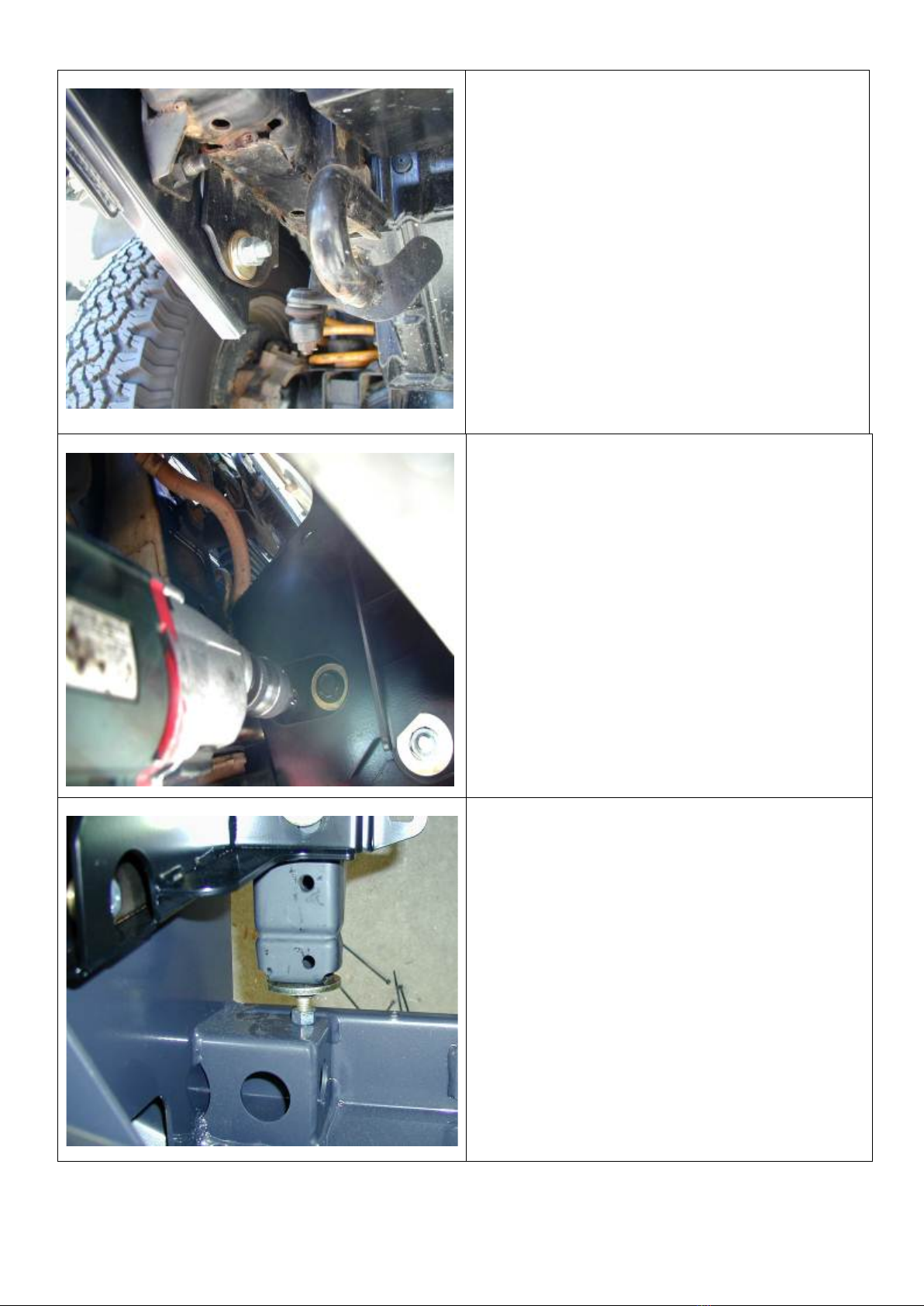
IMPORTANT
This winch bumper is suitable only for Warn winches up to 9500lb.

24-04-13 Page 2 of 12 3786417
USE.
PART NO.
QTY.
DESCRIPTION
CHASSIS BRACKETS TO
CHASSIS
4581088
2
Chassis rail extension adjuster bolt
6151096
7
Bolt M12 x 1.25 x 40mm
6151095
1
Bolt M12 x 1.25 x 35mm
6151135
2
Nut M12 x 1.25
6151189
2
Nut M12 x 1.75
4581049
2
Washer M12 Flat
4581050
8
Washer M12 Spring
4581007
8
Washer 13mm Heavy duty
4581008
2
Washer 13mm Offset heavy duty
6151087
2
Bolt M10 x 1.25 x 25mm
6151133
2
Nut M10 x 1.25
4581040
4
Washer M10 Flat
4581048
2
Washer M10 Spring
BULL BAR TO CHASSIS
BRACKETS
3756395L
1
Chassis bracket LHS
3756395R
1
Chassis bracket RHS
6151135
4
Nut M12 x 1.25
6151095
4
Bolt M12 x 1.25 x 35mm
4581050
4
Washer Spring M12
4581071
4
Washer shoulder M12
4581070
8
Washer Flat M12
TOP TUBE TO BAR
(5100050)
6131516
1
Top Tube assembly
6151255
2
Bolt M12 x 1.75 x 40mm
4581049
2
Washer M12 Flat
4581050
2
Washer M12 Spring
BUFFERS
(5100160 Required if fitting Top
Tube)
6151128
12
Flange nut M6
3162153
1
Buffer LH
3162154
1
Buffer RH
BUFFERS
(5100170
Required if not fitting Top Tube)
6151128
12
Flange nut M6
3162471L
1
Buffer LH
3162471R
1
Buffer RH
WINCH COVER
6522030
1
Panel winch cover
6151256
2
Button head screw M6 x 16mm
4581304
2
Washer flat M6 S/S
6151128
2
Flange nut M6
6191005
1
Winch cover extrusion
INDICATORS TO BULL BAR
3163015
1
Combination Light Surround Kit
180701
6
Scotch lock
6821152
2
Turn signal/clearance light loom
6821151L
1
TURN SIGNAL/CLEARANCE LIGHT
6821151R
1
TURN SIGNAL/CLEARANCE LIGHT
24-04-13 Page 3 of 12 3786417
USE.
PART NO.
QTY.
DESCRIPTION
NO. PLATE
6151017
2
Bolt M6 x 16mm
6151046
2
Washer flat M6
6151128
2
Flange nut M6
6781408
1
Double sided tape
AIR DEFLECTOR
6522873
1
Air deflector front
3314852
1
Air deflector extension
6151017
10
Bolt M6 x 16mm
6151046
10
Washer flat M6
6151128
7
Flange nut M6
6151315
3
Cage nut M6
WINCH FITMENT
3756499
1
Control box bracket
6151020
2
Bolt M8 x 16mm
4581044
2
Washer flat M8
6151132
2
Flange nut M8
4581040
4
Washer flat 3/8”
6151074
4
Bolt UNC 3/8” x 1 ¾”
BLB 560
3
Winch lead 560mm black
EG50
2
Rubber grommet
180302
10
Cable ties
AERIAL
3162152
2
CB aerial cap
TOOLS REQUIRED.
Basic tool kit: torque wrench, drill, 10mm drill bit, stepped ring spanners.
24-04-13 Page 4 of 12 3786417
BULL BAR PREPARATION
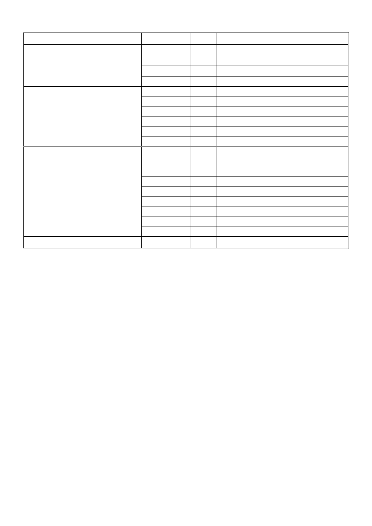
1. Assemble the two chassis brackets to
the bull bar using two per side, M12 x
35mm bolts, heavy duty D washers,
shoulder washers, heavy duty D
washers, spring washers and nuts.
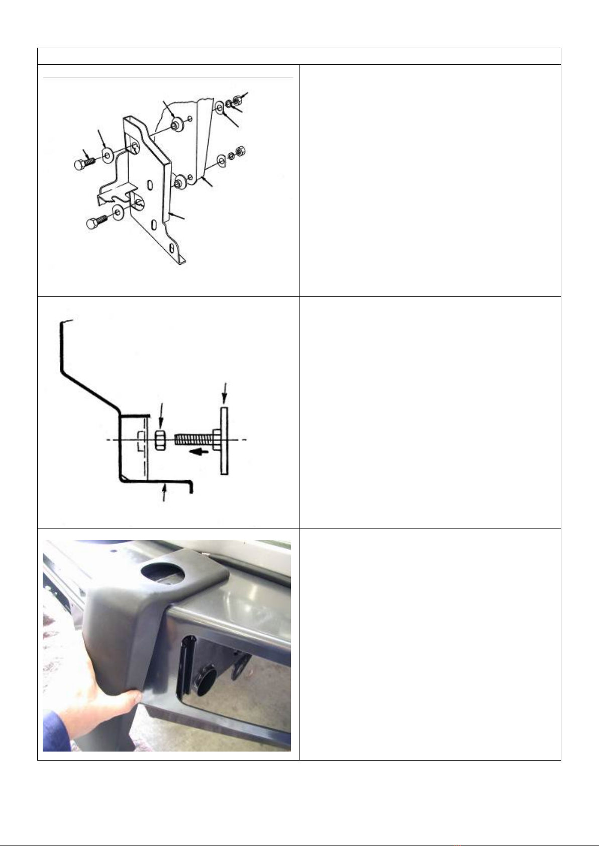
2. Position the impact absorbers centrally
on the upright slots. These slots were
provided to accommodate chassis height
variations.
3. Tighten the bolts firmly; though do not
fully tighten as they may be adjusted at
step 31.
4. Rest the bar face down on two stands so
assembly can be carried out.
5. Assemble a 12mm nut to each chassis
rail extension adjuster bolt and fully
screw into bull bar.
6. Do not tighten, as this will be adjusted
later.
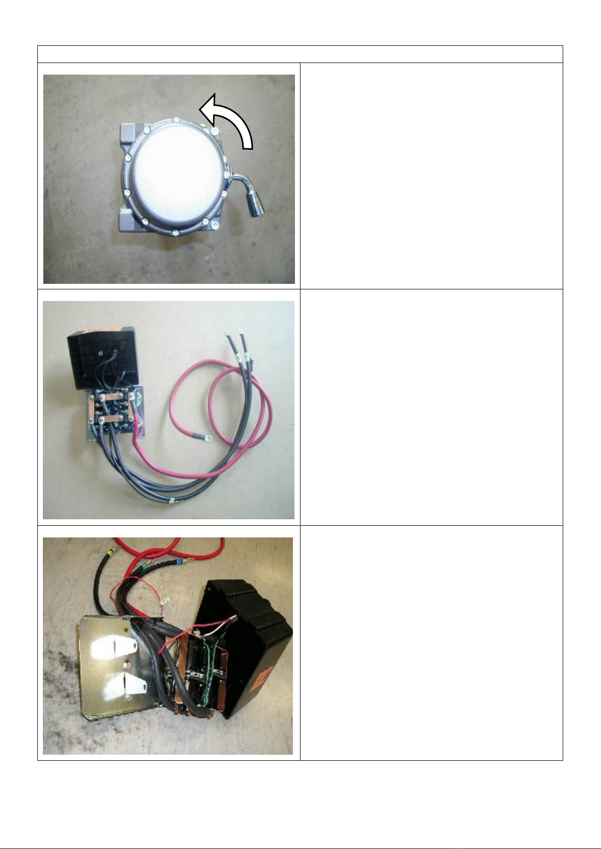
1. Fit the buffers. Buffer studs fit through
the slots in the wings and the pan.
Fasten using M6 flange nuts.
Note: This applies to both blank buffers and
for those with the hole for optional frame.
CAUTION: DO NOT OVER TIGHTEN THE M6
NUTS AS YOU RISK PULLING THE STUDS
OUT OF THE BUFFERS.
Chassis Rail Extension
Adjuster Bolt
(Wind Fully In)
Bull Bar
Bolt M12x35m
Washer 12mm
Shoulder Washer
Nut M12
Washer 12mm
Spring Washer
Bull Bar Upright (RHS)
Chassis Bracket (RHS)
24-04-13 Page 5 of 12 3786417
WINCH FITMENT
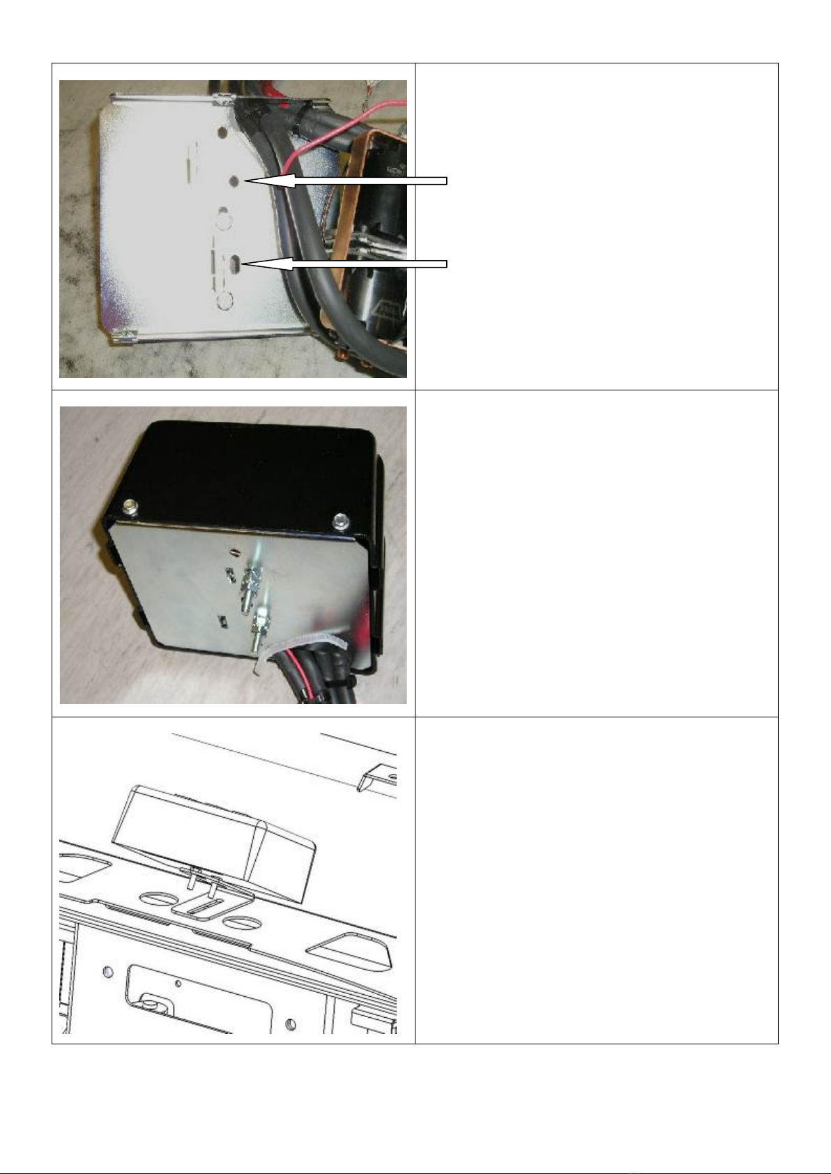
7. For ease of access the winch gearbox
handle needs to be rotated. To do this,
first undo all the cap screws and
carefully lift the gearbox clear of the
winch body so as not to damage the
gasket. (Do not lift the gearbox more
than a couple of millimetres) Rotate
the gearbox 144° anti clockwise. Re-fit
the caps-crews.
8. Remove the cover from the control box.
9. The three main power cables that go
from winch to control box must be
changed over using longer cables from
bolt kit. Make sure that you identify the
colour codes on the new cables before
re-fitting the control box cover.
NOTE: This must be done for whatever
winch is to be fitted to the bull bar.
10. If fitting the XP 9.5 winch, remove the
cover from the control box. Remove the
two cap screws, nuts and spacer
washers that hold the four solenoids in
place.
11. Remove the four solenoids from the
base of the control box using the copper
bus bar as an aid and hold to one side.
24-04-13 Page 6 of 12 3786417
12. Remove the two bolts in the base of the
control box and reposition them into the
more centralised holes.
13.
Replace the 4 solenoids, making sure
they line up with the holes in the base.
14.
Replace the 2 cap screws, washers and
nuts removed in step 13 above into
original holes.
15. Replace the black cover and refit the
three cover screws. (DO NOT OVER
TIGHTEN)
16.
Bolt the control box bracket to the
control box.
17. Fit the two grommets into the round
holes then thread the cable through.
18. Mount the control box bracket onto the
top pan, using M8 bolts, flat washers
and flanged nuts. Use the cable ties to
ensure the winch cables are secure,
clear of moving parts and sharp edges
and tie them together.

24-04-13 Page 7 of 12 3786417
19. Place winch on a stand with mounting
holes facing upwards and lower bull bar
onto winch. Align all four holes and
secure using 1 ½” x 3/8” bolts on top
holes and 1 ¾” x 3/8” bolts on lower
holes, plus 3/8” spring and flat washers.
20.
When all bolts are fitted and finger tight,
centralize bolts in holes and tighten top
holes only, using a stepped ring spanner.
21. Remove lower bolts.
22. Fit roller fairlead into cutout and refit bolts
and tighten firmly.
23. Connect the winch control box cables to
the winch. Refer to Warn installation
instruction manual when wiring up winch.
Ensure that all cables are installed well
clear of all sharp or moving parts, by
using cables ties from bolt kit.
BULL BAR FITMENT
FUNCTION
INDICATOR
HARNESS
VEHICLE COMBINATION LAMP
RIGHT
LEFT
TURN LAMP
GREEN
GREEN / RED
GREEN / YELLOW
EARTH
BLACK
BLACK
BLACK
PARK LAMP
RED
BLUE/BLACK
BLUE/BLACK
24. Remove the splash guards attached to
the bumper and remove the bumper and
grille from vehicle.
25. Remove the vehicle’s head lamps and
wire the indicator looms provided in the
kit to the vehicle’s indicator loom using
scotch locks. Leave these new looms
hanging freely for easy access when the
bar is fitted.
26. Re-attach the vehicle’s head lamps and
grille.

24-04-13 Page 8 of 12 3786417
27. Before fitting the bull bar, using black
paint, paint the section between bull bar
wing and the bottom of the headlight.
28. Position the bull bar on top of the
chassis rails and bolt into place using
the M12 x 40mm bolts, heavy-duty
washers and spring washers.(Do not
tighten)
NOTE: Due to variations in the vehicle
chassis rails it may be necessary to place a
packer between the chassis rail top and the
bull bar. A heavy-duty washer is supplied
for this purpose.
29. Fit M12 x 40mm bolts, spring washers
and heavy-duty flat offset washers
through bull bar side mounting holes into
original bumper bar captive nut mounting
holes. (Do not Tighten)
24-04-13 Page 9 of 12 3786417
30. Fit M12 x 40mm bolt (passenger’s side)
& M12 x 35mm bolt (driver’s side), ½”
flat washers, heavy duty flat washers,
spring washers and 12mm nuts to lower
bull bar mounting holes and vehicle tie
down plates. (Do not Tighten)
NOTE: Insert bolt from outside of lower
mount holes so heavy-duty washer covers
large hole on tie down plate.
31. Adjust the bull bar to achieve a uniform
gap to the grill and mudguards. If
additional height adjustment is required,
the M12 bolts fitted at step 5 may be
loosened for additional adjustment.
32. Tighten all the fitted bolts, including
those fitted at step 5, to a torque of
77Nm or 80 ft-lb.
33. Once the bar is secured, using the
10mm holes in chassis bracket as
template, drill 10mm hole through side of
chassis and secure using M10 x 40mm
bolt, flat washers, spring washer and nut.
34. Wind each impact absorber adjuster bolt
out until it is firm against the chassis rail
extensions and tighten the lock nut.

24-04-13 Page 10 of 12 3786417
IF FITTING TOP TUBE
35. Push the tube through the holes in the
top of the buffer and fix using the M12 X
40mm bolts washers and spring
washers.
36. Assemble and install combination light
surrounds (p/n 3163015) as per instructions
no. 3786421 supplied with surround kit. Note:
Optional fog lamps can be installed at this
point as per fitting instruction no. 3783315
supplied with fog lamp kit no. 6821201.
Wire the combination lamp to the vehicles
indicator and clearance lamps.
Caution: Cable tie all cables together and keep
all cables clear of sharp edges and moving
parts.
NOTE:
Torque these M12 fasteners to
44Nm only (Critical)

24-04-13 Page 11 of 12 3786417
37. Fit three M6 cage nuts to the upper
deflector panel as shown on the left.
38. For non-4.8 litre petrol engine vehicles,
assemble the second deflector panel
using M6x16mm bolts, washers and
flange nuts as shown on the left.
39. 4.8 litre petrol engine vehicles only
require the upper panel to be fitted to the
vehicle.
40. Fit the air deflector / deflectors using M6
nuts and bolts.
41. Fit three M6x16 bolts and washers
through the front of the upper deflector
into the cage nuts previously installed.
42. Fit two M6x16 bolts through the two slots
on each side of the deflector. Use M6
washers and flange nuts to fasten the
deflector to the mating impact absorbers.
These slots are accessible through the
cut-outs in the deflector.

24-04-13 Page 12 of 12 3786417
43. If no winch is fitted to the bar, wrap
rubber extrusion around winch cover.
44. Place stainless steel washers over the
winch cover fixing holes located on the
top middle face of the winch bar.
45. Place the winch cover on top of the bar
inline with the mount holes. Bolt together
using the M6 button head stainless steel
screws and M6 nuts.
46. Place the double-sided tape along the
top edge of the licence plate. Fit number
plate to bar using M6x16 bolts, washers
and flange nuts. The two photos display
the number plate positions for winch and
non-winch bars.
47. There are two diameter 16 holes located
on the top face of the bar. If no CB
aerials are fitted the holes can be
covered with the plastic plugs provided in
the fitting kit.
48. When finished make sure all bolts are
tightened and that all wiring is clear of
hot, sharp and moving parts.
This manual suits for next models
3
Table of contents
Other ARB Automobile Accessories manuals


ARB
ARB AIRLOCKER RD109 User manual

ARB
ARB Flinders User manual

ARB
ARB AIRLOCKER RD136 User manual

ARB
ARB AIRLOCKER RD189 User manual

ARB
ARB Airlocker RD161 User manual

ARB
ARB Airlocker RD146 User manual

ARB
ARB AIRLOCKER RD156 User manual

ARB
ARB Airlocker RD167 User manual

ARB
ARB AIRLOCKER RD127 User manual

ARB
ARB AIRLOCKER RD142 User manual


Popular Automobile Accessories manuals by other brands


ULTIMATE SPEED
ULTIMATE SPEED 279746 Assembly and Safety Advice

SSV Works
SSV Works DF-F65 manual

ULTIMATE SPEED
ULTIMATE SPEED CARBON Assembly and Safety Advice

Witter
Witter F174 Fitting instructions

WeatherTech
WeatherTech No-Drill installation instructions

TAUBENREUTHER
TAUBENREUTHER 1-336050 Installation instruction