ARB 341 4460 User manual
05/10/11 Page 1 of 21 378 7983
If you have any queries regarding the installation of this product please contact the distributor from whom it was purchased, or alternatively the ARB office in your state.
Head Office – ARB Corporation Ltd VIC: 42-44 Garden Street, Kilsyth, Victoria, 3137 Tel: (03) 9761 6622 Fax: (03) 9761 6807
WA: (08) 9244 3553 NSW: (02) 9821 3633 ACT: (02) 6280 7475 SA: (08) 8244 5001 QLD: (07) 3872 3872 NT: (08) 8947 2262 TAS: (03) 6331 4190
HILUX ARB BULL BAR, 2011 ONWARDS
(SRS AIR BAG EQUIPPED MODELS)
PRODUCT NUMBER: -
341 4460 - Winch Bull Bar, to suit flared vehicles only.
341 4450 – Winch Bull Bar to suit non-flared vehicles only.
321 4460 - Bull Bar Non Winch, to suit flared vehicles only.
321 4450 – Bull Bar Non Winch to suit non-flared vehicles only.
FITTING KIT: -
6173152 -To suit winch bull bars. (341 4450/60)
6173155 - To suit non-winch bars. (321 4450/60)
WARNING
NOTE THE FOLLOWING: -
♦This product must be installed exactly as per these instructions using only the hardware supplied.
♦In the event of damage to any bull bar component, contact your nearest authorised ARB stockist.
Repairs or modifications to the impact absorption system must not be attempted.
♦Do not use this product for any vehicle make or model, other than those specified by ARB.
♦Do not remove labels from this bull bar.
♦This product or its fixing must not be modified in any way.
♦The installation of this product may require the use of specialized tools and/or techniques
♦It is recommended that this product is only installed by trained personnel
♦These instructions are correct as at the publication date. ARB Corporation Ltd. cannot be held
responsible for the impact of any changes subsequently made by the vehicle manufacturer
♦During installation, it is the duty of the installer to check correct operation/clearances of all
components
♦Work safely at all times
♦Unless otherwise instructed, tighten fasteners to specified torque

05/10/11 Page 2 of 21 378 7983
GENERAL CARE AND
MAINTENANCE
By choosing an ARB Bar, you have bought a product that is one of the most sought after 4WD
products in the world. Your bar is a properly engineered, reliable, quality accessory that represents
excellent value. To keep your bar in original condition it is important to care and maintain it following
these recommendations:
Prior to exposure to the weather your bar should be treated to a Canuba based polish on all
exposed surfaces. It is recommended that this is performed on a six monthly basis or following
exposure to salt, mud, sand or other contaminants.
As part of any Pre Trip Preparation, or on an annual basis, it is recommended that a thorough
visual inspection of the bar is carried out, making sure that all bolts and other components are
torqued to the correct specification. Also check that all wiring sheaths, connectors, and fittings are
free of damage. Replace any components as necessary. This service can be performed by your
local authorized ARB Stockist.
HAVE AVAILABLE THESE SAFETY ITEMS WHEN FITTING PRODUCT: -
Protective eyewear Hearing protection
NOTE: ‘WARNING’ notes in the fitting procedure relate to OHS situations, where to avoid a
potentially hazardous situation it is suggested that protective safety gear be worn or a safe
work procedure be employed. If these notes and warnings are not heeded, injury may result.
FASTENER TORQUE SETTINGS: -
SIZE Torque Nm Torque lb/ft
M6 9Nm 4lbft
M8 22Nm 16lbft
M10 44Nm 32lbft
M12 77Nm 57lbft

05/10/11 Page 3 of 21 378 7983
USE PART No QTY
DESCRIPTION
3756499 1 CONTROL BOX BRACKET
6151234 2 BOLT, M8 x 1.25 x 25 LONG (BLACK)
CONTROL BOX FITMENT 4581045 2 WASHER FLAT M8 (BLACK)
(WINCH ONLY) 6151132 2 NUT FLANGE M8
EG50 2 GROMMET RUBBER
180302 8 CABLE TIES
4581040 2 WASHER FLAT 3/8”
WINCH (8000/9000/9500 LB) 6151074 2 BOLT UNC 3/8” x 1 ¾”
BLB850 3 CABLE BLACK 850mm
6151304 4 NUT CAGE M10
4581040
8 WASHER FLAT M10
IMPACT ABSORBER TO BULL BAR 4581288 4 WASHER FLAT M10 (OVER-SIZED)
4581048
8 WASHER, SPRING, M10
6151232
8 BOLT, M10 x 1.5 x 30 LONG
6151026 4 NUT, HEX, M10 x 1.5
3162470R 1 BUFFER (RH)
BUFFERS TO BULL BAR 3162470L 1 BUFFER (LH)
6151128 12 NUT FLANGE M6
NUMBER PLATE TO BULL BAR 6821189 2 GROMMET ROUND FL
6151384 2 SCREW PAN HD PHIL BLK 5 X 16mm
INDICATORS TO BULL BAR
6821151R 1 INDICATOR KIT, RHS
6821151L 1 INDICATOR KIT, LHS
6821116 4 NYLON PLUG
6151308 4 SCREW, SELF TAPPING
6821152 2 WIRING LOOM
6821198 1 INDICATOR RELAY LOOM
3163052R 1 TRIM, WING (LH), HILUX 11
WING TRIM FITMENT 3163052L 1 TRIM, WING (RH), HILUX 11
4581082 10 WASHER, FLAT, M6 (BLACK, 20 OD)
6151384 2 PAN HEAD SCREW 5X16MM BZ
6151162 8 NUT, NYLOC, M6x1
3756721 1 BRKT, CHASSIS MOUNT, HILUX 05
IMPACT ABSORBER TO CHASSIS 4581040 4 WASHER, FLAT, M10
4581048
4 WASHER, SPRING, M10
6151133 4 NUT, M10 x 1.25
3199756R 1 PLATE (RH), CHASSIS, HILUX 05
3199756L 1 PLATE (LH), CHASSIS, HILUX 05
CHASSIS STIFFENING PLATE 6151088 6 BOLT, M10 x 1.25 x 35 LONG
TO CHASSIS & IMPACT 4581040 12 WASHER, FLAT, M10
ABSORBER 4581048 6 WASHER, SPRING, M10
6151133 6 NUT, M10 x 1.25
3758129 1 BRKT GRILL MNT HILUX 05
LOWER GRILL BRACKET 6151234 2 BOLT, M8 x 1.25 x 25 LONG (BLACK)
4581045 2 WASHER, FLAT, M8 (BLACK)
4581047 2 WASHER, SPRING, M8 (BLACK)
6151132 2 NUT FLANGE M8
3163006 1 FOG LAMP SURROUND RHS
FOG LAMPS TO BULL BAR 3163005 1 FOG LAMP SURROUND LHS
6821183 2 FOG LAMP LOOM

05/10/11 Page 4 of 21 378 7983
6522649 1 PANEL STONE GUARD UPPER HILUX 05
6522650 1 PANEL STONE GUARD LOWER HILUX 05
6151303 8 CAGE NUT, M8 (3mm PLATE)
CENTRE STONE DEFLECTORS 4581045 8 WASHER, FLAT, M8 (BLACK)
4581047
8 WASHER, SPRING, M8 (BLACK)
6151234
8 BOLT, M8 x 1.25 x 25 LONG (BLACK)
6522816R 1 PANEL, WING (RH), HILUX 11
6522816L 1 PANEL, WING (LH), HILUX 11
6151315 10 CAGE NUT, M6 (1.6mm PLATE)
4581082 10 WASHER, FLAT, M6 (BLACK, 20 OD)
WING STONE DEFLECTORS 4581287 10 WASHER, SPRING, M6 (BLACK)
6151213 10 BOLT, M6 x 1.0 x 20 (BLACK)
6151094 2 BOLT M12 x 1.25 x 30 LONG
4581049 2 WASHER, FLAT M12
4581050 2 WASHER, SPRING M12
6151234 2 BOLT, M8 x 1.25 x 25 LONG (BLACK)
6151303 2 CAGE NUT, M8 (3mm PLATE)
4581045 2 WASHER, FLAT, M8 (BLACK)
4581047 2 WASHER, SPRING, M8 (BLACK)
3758190R 1 BRACKET WING STONE SHIELD RH
3758190L 1 BRACKET WING STONE SHIELD LH
Tools required: -
10 mm & 5 mm drill bits and a electric drill, Satin black can of spray paint, scissors or
sharp knife, metric ruler, basic metric spanner and socket set & screw driver set, neutral
cure silicon, and a stepped ring spanner to suit 3/8” bolt. (If installing a winch)

05/10/11 Page 5 of 21 378 7983
ASSEMBLY SEQUENCE FOR BULL BAR INSTALLATION.
1. Remove existing bumper and grill from
the vehicle.
Once these are removed:
-Remove the light bracket fitting and
discard; this is done by first removing
the light and then unscrewing the
bracket from the rear of the light fitting.
-Remove the bumper braces and
discard.
-Remove the chassis cross-brace and
discard.
-Remove the factory fog lamps from the
bumper bar and keep aside.
2. Remove the plastic bumper retention
blocks from either side of the vehicle.
3. Replace the front most screws (these
secure the head lights).
4. Spray paint the metal underside of the
fender and the underside of the
headlamp black.
Ensure the area to be painted is well
masked to ensure no over spray on other
components.

05/10/11 Page 6 of 21 378 7983
5. Fasten the lower grill bracket to the
vehicle head lights, as shown, using M8
x 25 black bolts, flat washers, spring
washers and flange nuts.
6. Reassemble the vehicle’s grill removed
at step 1; make sure the 2 lower grill
tabs are pushed into the clips in the
lower grill bracket. Bend lower grill
bracket tab upwards slightly.
7. Remove the vehicles headlights.
8. Carefully read the wiring diagram
supplied at the end of these
instructions.
9. Take the relay loom (6821198) from the
kit and position in the engine bay so
that all wires will reach the appropriate
connections.
05/10/11 Page 7 of 21 378 7983
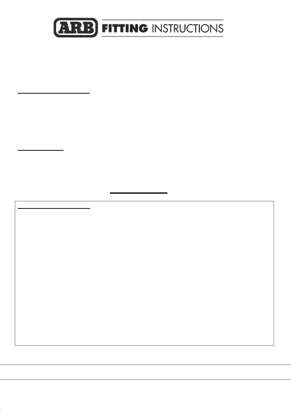
10.Starting with the passenger side, use
scotch locks to connect the red wire
from the indicator loom (6821152) to
the green wire from the vehicles front
park lamp.
11.Connect the Yellow / Black wire from
the relay loom to the Green / Black wire
from the vehicles left indicator.
12.Connect the Yellow and Black wires
from the relay loom to the Green and
Black wires from the indicator loom.
13.Let the indicator loom hang freely for
connecting to the bull bar indicators
later on.
14.Do the same for the drivers side using
the wiring diagram supplied as a
reference for the correct wire colors.
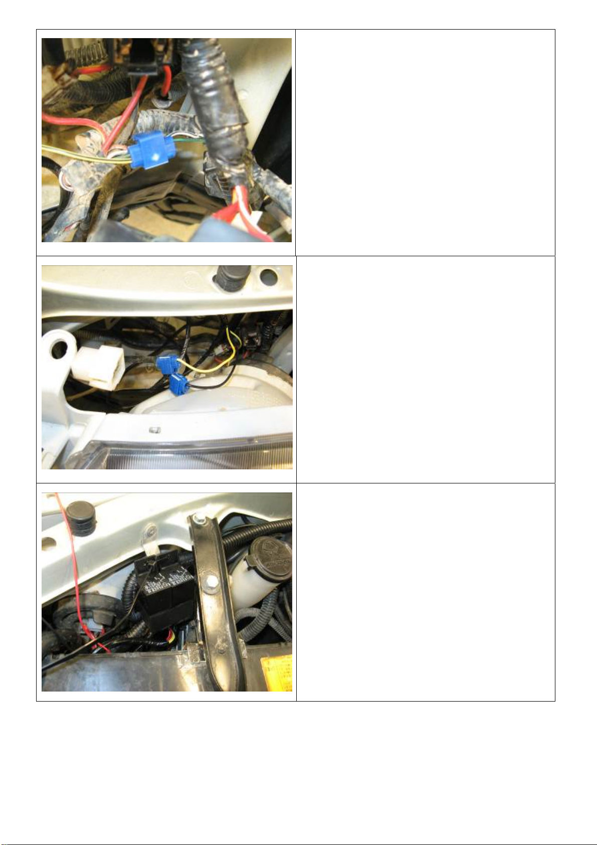
15.Find a suitable place and mount the
relay.
NOTE: Always mount the relay upright
to help prevent water ingress.

05/10/11 Page 8 of 21 378 7983
16.Run the main black wire to a suitable
earth.
17.Connect the main power wire (red) to
the positive terminal of the battery.
(Main battery if a dual battery system is
installed)
18.Using the cable ties supplied, secure
the loom being sure to keep clear of
any hot, sharp or moving surfaces.
19.Remove the protruding bracket in front
of the radiator, as it is no longer
required (note: the vertical member of
this bracket must not be removed as it
holds the bonnet latch in position). This
may be done by either drilling out the
existing spot-welds with a 5mm drill as
shown, or by cutting it off with a grinder.
Re - locate the air temp sender (if fitted)
to one of the holes in the vertical
bracket.
Paint exposed metal to prevent rusting.
CABLE TIE
LOOM

05/10/11 Page 9 of 21 378 7983
20.Fit the buffers to the bull bar using the
6mm flange nuts provided.
(DO NOT OVER TIGHTEN)
21.Fit cage nuts and nylon plugs to the
bull-bar.
M10 cage nuts. (4 off) Caged portion is to
centre of bull bar.
M8 cages nuts. (4 off) Caged portion is to top
of bull bar.
22.Remove the fastening screws and nuts
supplied with the turn signal/clearance
lamps and replace these with the four
screws provided in the kit. Push the
square plastic plugs into the holes on
the turn signal bracket. Fasten the turn
signal lamps to the bull bar as shown.
NOTE: - The drain holes in the lamp are at the
bottom. (As shown)
IMPORTANT: -
The turn signal (amber section) is to face to
the inside of the bull bar.
Drain Holes

05/10/11 Page 10 of 21 378 7983
23.Fit the factory fog lamp to the bull bar
bracket by engaging the peg on the fog
lamp (right hand side shown) into the
hole in the out board (shorter) side of
the bracket as shown.
24.Align the black clip located at the back
of the lamp into the corresponding hole
in the bracket.
Push the inner edge of the fog lamp into the
bracket to fully retain the fog lamp.
25.To ensure a tight fit of the fog lamp into
the bracket bend the tabs on the
bracket in towards the lamp with a
screwdriver.
Repeat this on the other side.
NOTE: - If the removal of the fog light is
necessary pry the tabs outward from the
lamp and using a screw driver between the
body of the lamp and bracket on the inner
(longer) side of the bracket flex the bracket
to disengage the fog lamp post from the
bracket.
26.The fog lamp surround is held to bar
using silicon adhesive. Apply a bead of
silicon adhesive around light cut out on
the bull bar and hold the fog light
housing to the bull bar using masking
tape until the silicon adhesive dries,
then remove the tape.

05/10/11 Page 11 of 21 378 7983
27.Loosely fit the wing trims using 5
oversized M6 washers, 4 M6 nyloc nuts
and 1 self-tapping screw on each side
of the bar
These nuts will be tightened after the bar
has been fitted to the vehicle and the wing
trims have been positioned in an optimal
position.
TO FIT A WINCH BAR
(If not fitting a winch proceed to step 51)
28.To fit an 8/9/9.5/000lb winch, rotate
gearbox 72° counterclockwise.
29.Stand the winch upright and undo the
capped head screws. Lift the gearbox
up - only a couple of millimeters, to
allow the gearbox to be rotated to the
new position. Once in position, refit all
screws and tighten firmly.
WARNING: Do not lift gearbox more than a
couple of millimeters.
ORIGINAL
ROTATED
VIEWED FROM
LHS OF VEHICLE

05/10/11 Page 12 of 21 378 7983
30.Remove the cover from the control box.
31.Replace the three main power cables
that go from winch to control box. Make
sure that you identify the colour codes
on the new cables before closing
control box cover.
32.This must be done for whatever winch
is to be fitted to the bull bar.
33.If fitting the XP 9.5 winch, remove the
cover from the control box, otherwise
proceed to step 36.
Remove the two cap screws, nuts and
spacer washers that hold the four
solenoids in place.
34.Remove the four solenoids from the
base of the control box using the
copper bus bar as an aid and hold to
one side.
05/10/11 Page 13 of 21 378 7983
Before
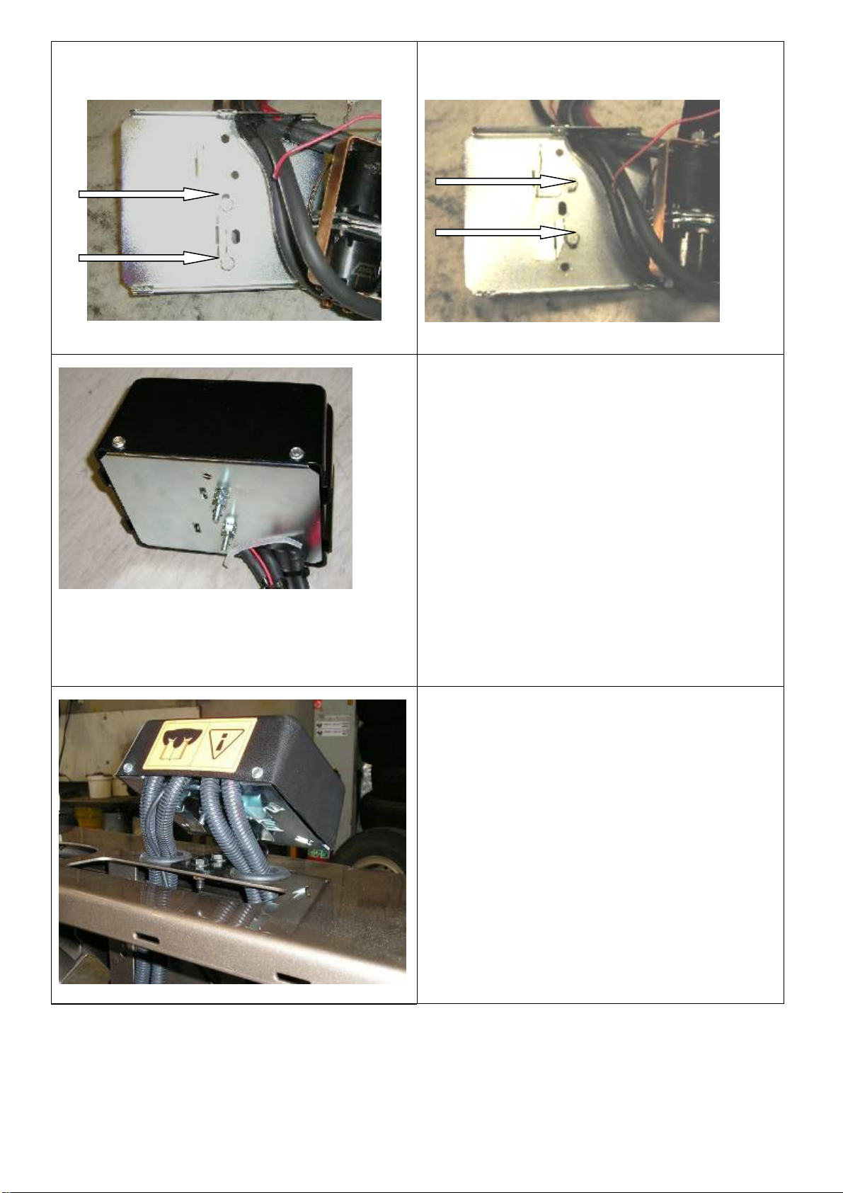
35.Remove the two bolts in the base of the
control box and reposition them into the
more centralized holes.
After
36.Place the 4 solenoids over the 2 metal
stands that are facing upwards. Make
sure they line up with the holes in the
base.
37.Replace the 2 cap screws, washers
and nuts removed in step 14 above into
original holes.
Replace the black cover and refit the three cover
screws. (DO NOT OVER TIGHTEN)
38.Bolt the control box bracket to the
control box.
39.Fit the two grommets into the round
holes in the top of the bull bar then
thread the cables through.
40.Mount the control box bracket onto the
top pan, using M8 bolts, flat washers
and flanged nuts. Use the cable ties to
ensure the winch cables are secure,
clear of moving parts and sharp edges
and tie them together.
05/10/11 Page 14 of 21 378 7983
41.Place winch on a stand with mounting
holes facing upwards and lower bull bar
onto winch. Align all four holes, using
the original 3/8” bolts that came with
the winch in the top two holes and the
longer 1 ¾” x 3/8” bolts, supplied in the
kit, in the lower two holes plus 3/8”
spring and flat washers with each bolt.
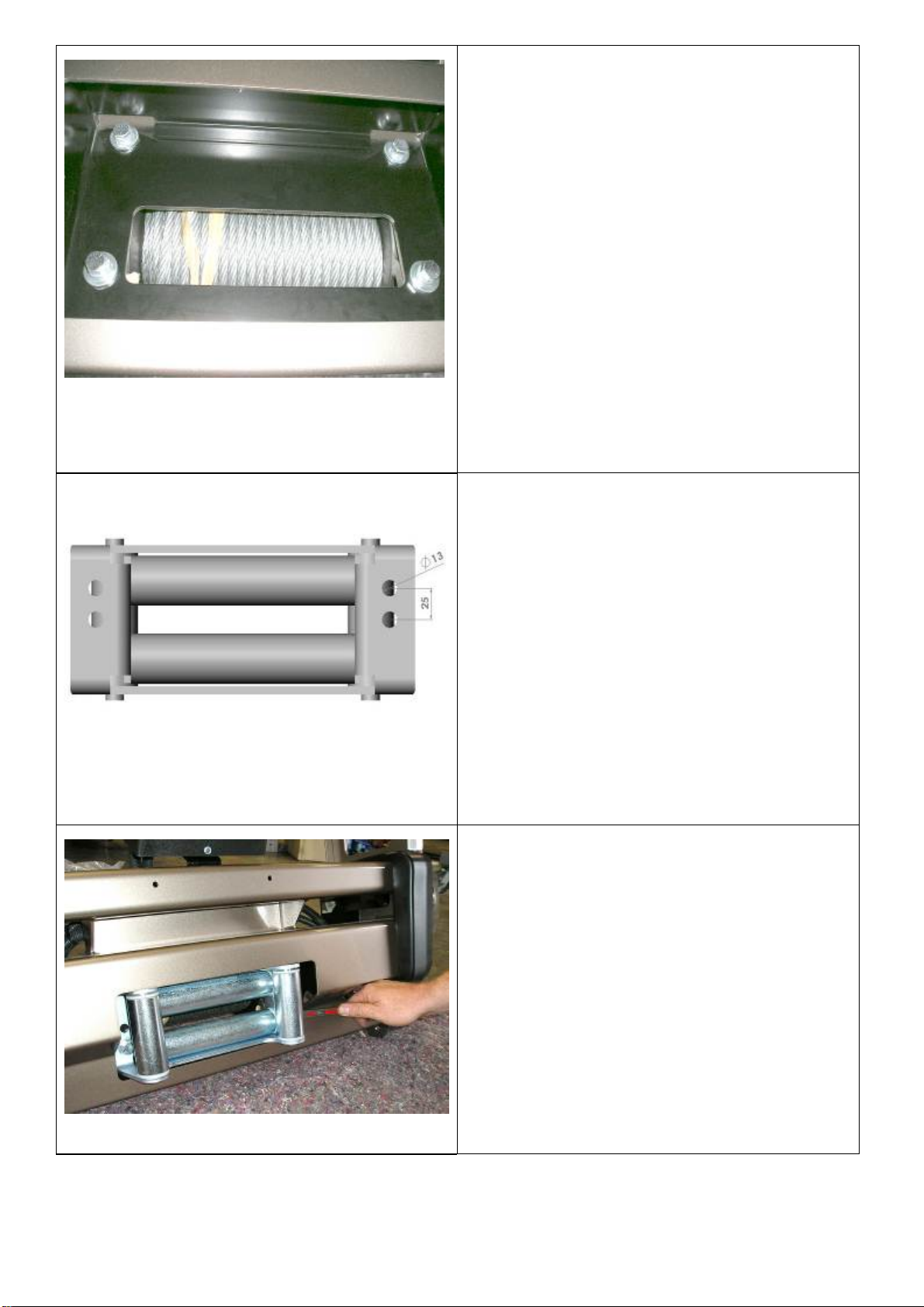
42.When all bolts are fitted and finger tight,
tighten top holes only, using a stepped
ring spanner and remove lower bolts.
Drill two new 13mm holes in the roller
fairlead provided in the kit, as shown on
the adjacent picture.
43.Fit roller fairlead into cutout and refit
bolts and tighten firmly.
NOTE. For ease of tightening the lower bolts,
use a stepped ring spanner.
\

05/10/11 Page 15 of 21 378 7983
44.Connect the winch control box cables
to the winch. Refer to Warn installation
instruction manual when wiring up
winch.
45.Ensure that all cables are installed well
clear of all sharp or moving parts, by
using cables ties from bolt kit.
46.Cable tie main cables that go to battery
in between underside of bar and brace.
Refer to photo to see where to cable tie to bull bar.
47.Fit the impact absorber to the bull-bar
using the two M10 x 30 bolts as shown,
M10 over-sized washers and M10
spring washers. Do not fully tighten
these bolts as they will be tightened on
the vehicle.
48.Fit four M8 cage nuts to the impact
absorber. (Cage nuts to suite 3mm
plate) Caged portion to top of bull bar.
49.Position the bar on the vehicle and
fasten it to the chassis studs using the
M10 washers, spring washers and nuts
provided. Once satisfied that the bar is
centrally positioned on the vehicle
properly tighten the M10 nuts.

05/10/11 Page 16 of 21 378 7983
50.Adjust the bull bar position up/down
and in/out to achieve uniform gaps
between the bar and the fenders on
each side of the vehicle. The nominal
clearance between the bull-bar and the
fenders is 20mm. Firmly tighten the
bolts fitted at step 46.
Once satisfied with the position of the bull-bar,
using a 10mm drill, drill through the 10mm
holes in the impact absorber, 2 holes per side,
and secure using the M10 x 30 bolts, two flat
washers per bolt, spring washers and hex
nuts.
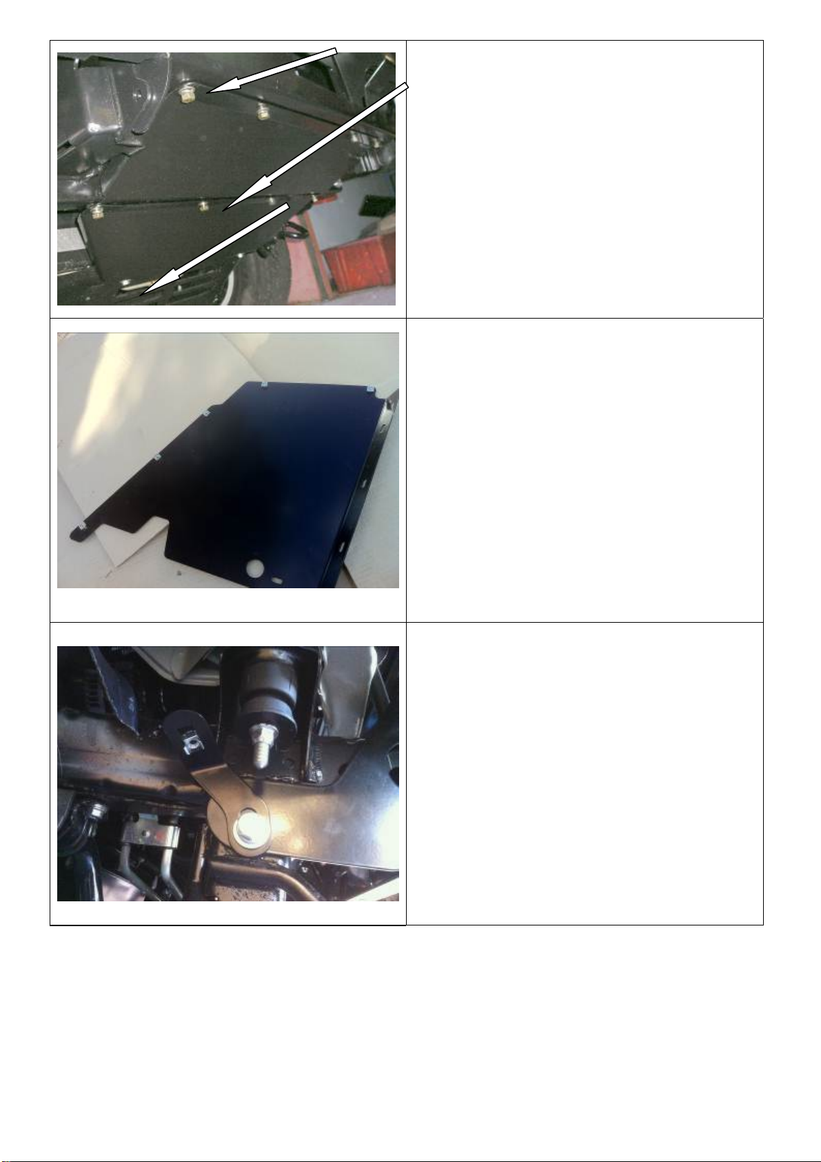
51.Fasten the chassis-stiffening bracket to
the chassis and the impact absorber as
shown. Fasteners required include: six
M10 x 35 bolts, twelve M10 flat
washers, six M10 spring washers, six
hex nuts
Leave this bolt hole clear for step 54.
05/10/11 Page 17 of 21 378 7983
52.Fit the centre stone guards as shown
using M8 x 25 black bolts, black M8 flat
washers and black M8 spring washers.
Use the original bolts in the lower two
holes.
53.Fit theM6 cage nuts to the wing stone
guards as shown.
Make sure the plastic wheel liner on the LH
side of the vehicle has been disconnected
from the washer bottle before fitting the wing
stone guards.
54.Fit the M8 cage nuts to the stone guard
brackets.
Loosely fit the brackets to the side of the
chassis rails using M12 x 30 Hex bolts, M12
Spring washers and M12 Washers.
05/10/11 Page 18 of 21 378 7983
55.Fit the wing stone guards to the bull bar
/ vehicle using M6 x 20 black bolts, M6
black washers, M6 black spring
washers.
Use the M8 x 25 black bolt, M8 black
flat washer and M8 black spring washer
to secure the stone guard to the
bracket fitted in step 55.
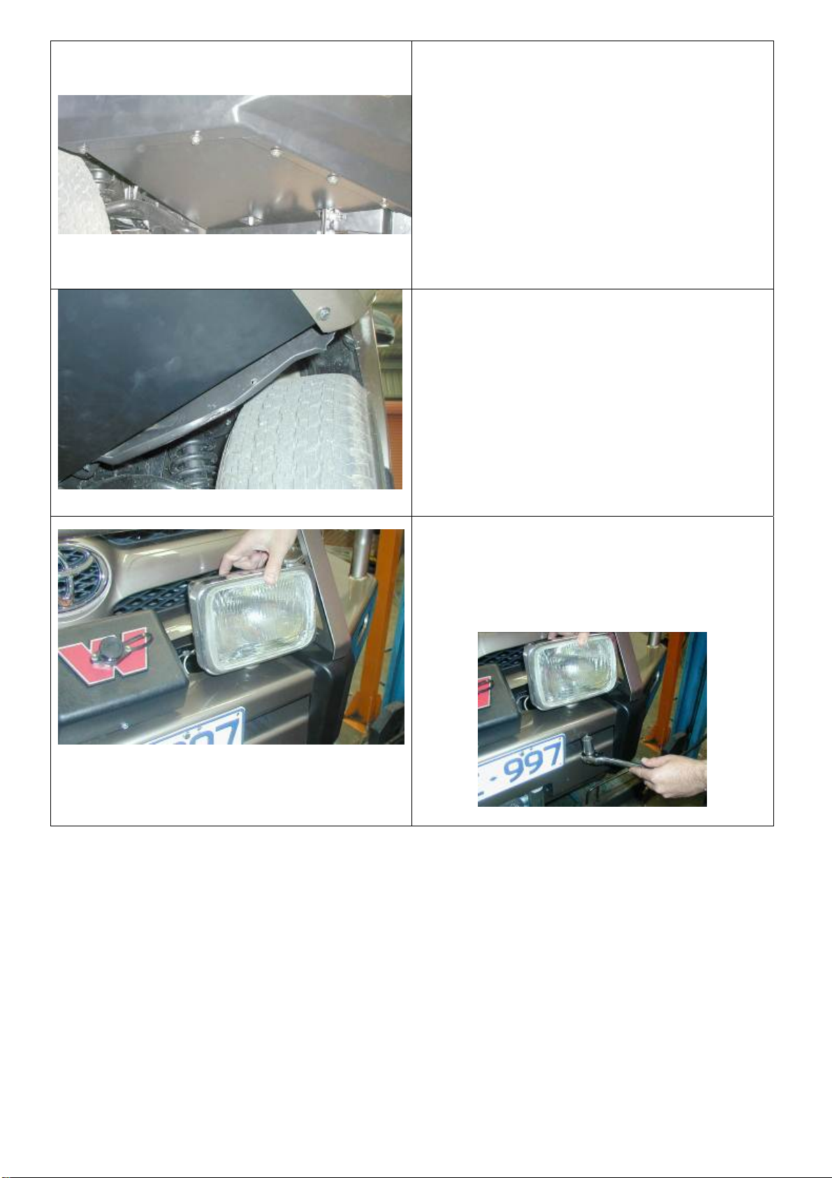
56.Mark lines along the inner guards using
the bottom edge of the stone guards as
a guide.
57.Remove the stone guards and cut
along the lines marked in the previous
step.
58.Tuck the inner guards into the stone
guards.
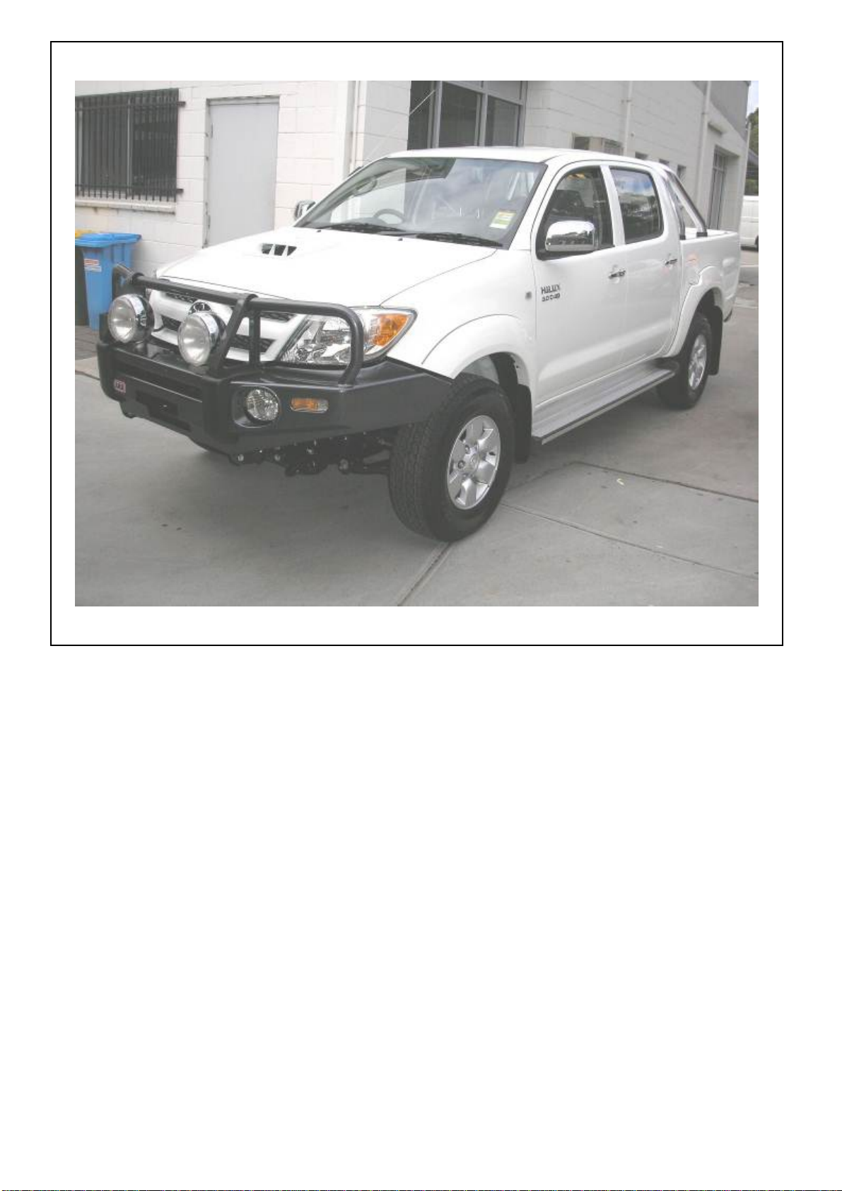
59.If fitting optional driving lights to vehicle
do so at this stage. Guide ratchet
spanner between the upper and lower
pans, as shown, to tighten the lights to
the bar.

05/10/11 Page 19 of 21 378 7983
60.Fit the plastic plugs into the square
holes in the lower or upper pan
depending on fitment. Fit the number
plate to the bull bar using the black self-
tapping screws.
The two photos display the number plate
positions for both winch and non-winch bars.
Provision for a high-lift jack has been provided
on both sides of bar.
05/10/11 Page 20 of 21 378 7983
Another photo for non winch
This manual suits for next models
5
Table of contents
Other ARB Automobile Accessories manuals


ARB
ARB Airlocker RD162 User manual

ARB
ARB AIRLOCKER RD208 User manual

ARB
ARB RD246 Product information sheet

ARB
ARB Airlocker RD161 User manual

ARB
ARB Airlocker RD152 User manual

ARB
ARB Airlocker RD259 User manual

ARB
ARB AIRLOCKER RD156 User manual

ARB
ARB 3414470 User manual

ARB
ARB 10900013 User manual

ARB
ARB RD177 User manual


Popular Automobile Accessories manuals by other brands


ULTIMATE SPEED
ULTIMATE SPEED 279746 Assembly and Safety Advice

SSV Works
SSV Works DF-F65 manual

ULTIMATE SPEED
ULTIMATE SPEED CARBON Assembly and Safety Advice

Witter
Witter F174 Fitting instructions

WeatherTech
WeatherTech No-Drill installation instructions

TAUBENREUTHER
TAUBENREUTHER 1-336050 Installation instruction