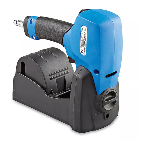
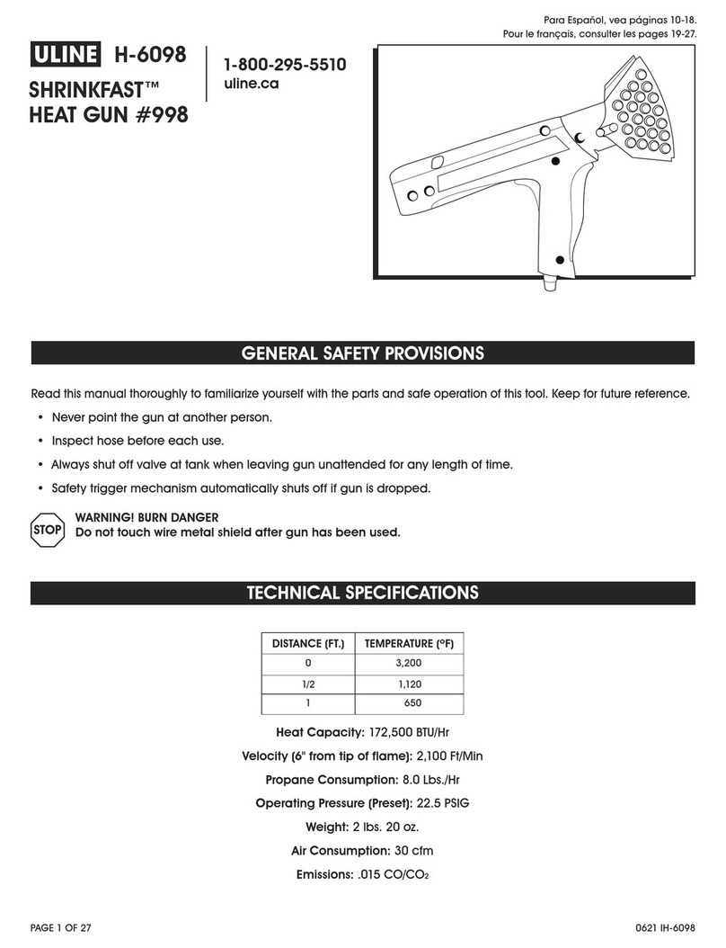
U-Line SHRINKFAST 998 User manual

PAGE 1 OF 27 0621 IH-950
H-950
SHRINKFAST™
HEAT GUN #998
1-800-295-5510
uline.com
Read this manual thoroughly to familiarize yourself with the parts and safe operation of this tool. Keep for future reference.
• Never point the gun at another person.
• Inspect hose before each use.
• Always shut off valve at tank when leaving gun unattended for any length of time.
• Safety trigger mechanism automatically shuts off if gun is dropped.
WARNING! BURN DANGER
Do not touch wire metal shield after gun has been used.
DISTANCE (FT.) TEMPERATURE (ºF)
03,200
1/2 1,120
1650
TECHNICAL SPECIFICATIONS
GENERAL SAFETY PROVISIONS
Heat Capacity: 172,500 BTU/Hr
Velocity (6" from tip of flame): 2,100 Ft/Min
Propane Consumption: 8.0 Lbs./Hr
Operating Pressure (Preset): 22.5 PSIG
Weight: 2 lbs. 20 oz.
Air Consumption: 30 cfm
Emissions: .015 CO/CO2
Para Español, vea páginas 10-18.
Pour le français, consulter les pages 19-27.

PAGE 2 OF 27 0621 IH-950
SHRINK FILM
Use only with shrink film (not all plastic films are shrink
film). Shrink film should be virgin plastic, not reprocessed
material. For light loads of 100 lbs. or less, 3 mil thick film
should work. For heavy weights or items (example, steel
drums at 2,000 lbs./pallet), use 6 mil or thicker shrink film.
• Gusseted film shrinks equally in both directions,
and tends to pull up and away from pallet. Length
should be longer than the height of the pallet.
• Centerfold film shrinks mainly in one direction and
has a reduced tendency to pull up off of pallet.
SHRINK BAG
Most bags list lay-flat length and width. To determine
what size bag you need, use the following example:
Load size: 47 x 30 x 36" (L x W x H)
Calculate the width of bag:
1. Add the width and length
30 + 47" = 77"
2. Add Fitting Allowance (4" to allow for ease of fit)
4 + 77" = 81" (This is the width bag you’ll need.)
Calculate the length of the bag:
1. Use 1/2 the length of the shorter side
1/2 of 30" = 15"
2. Add number from Step 1 to height
15 + 36" = 51"
3. Add Shrink Allowance (1" for each foot of height)
36" = 3', so 3" shrink allowance
51+ 3" = 54" (This is the length bag you’ll need.)
4. Bag size is 54 x 81" (L x W).
PROPANE TANK
Use only with vapor withdrawal propane tanks, NEVER
attach heat gun to a liquid withdrawal propane tank.
WARNING! Using a liquid withdrawal propane
tank clogs the orifice filter and may result in an
extremely dangerous long flame.
Tanks are available in 6, 8, 10, 20, 30 and 40 lb. sizes.
6 lb. tanks are adequate for intermittent use. Use larger
tanks for continuous use.
Tank Pressure – Depends on tank temperature. At 72ºF,
pressure is 110 PSI; at 0ºF, pressure drops to 22 PSI. In
use, tank pressure drops due to evaporation process of
converting liquid propane to propane gas. Tank may
drop to 0ºF with ice appearing on the outside. Propane
pressure may drop below 15 PSI.
WARNING! DO NOT run the gun when tank
pressure drops below 15 PSI.
• For continuous operation, use multiple tanks,
switching the gun from one to another.
• Using an ordinary desk fan to blow air on the tank
will prevent it from icing up.
VENTILATION
In use, this heat gun produces carbon dioxide, carbon
monoxide and water vapor.
WARNING! Prolonged exposure to carbon
monoxide (CO) is lethal. Provide adequate
ventilation when gun is used indoors.
To maintain a safe CO concentration (50 parts per
million as set by OSHA Standard 1910.93), ventilation
requirements are 2,000 cu. ft./min. of fresh air while gun
is operated at maximum operating pressure of 30 PSI.
Ventilation capacity should be sized proportionally for
different production rates.
EXAMPLE: Based on a 1½ minute heating cycle
per pallet, fresh air requirements are 3,000 cu.
ft./pallet.
If the production rate is 10 pallets/
hour,
a ventilation system needs to provide
500 cu. ft./minute.
In areas where ventilation is provided by open doors or
windows, safe CO levels will be maintained as long as
room temperature does not exceed 150ºF.
GENERAL INFORMATION
PAGE 3 OF 27 0621 IH-950
15
789
2
4
3
1
5
13
10
11
12
14
16
Side View
Attached Tank
(Top View)
6
CONNECTIONS
1. Connect gun, hose and regulator to the
tank. Use a wrench to tighten fittings (lefthand
threaded). (See Figure 1)
2. Check for leaks.
• Open tank valve without pushing trigger to
pressurize the hose. Pressure gauge should read
15 to 30 PSI when gun is not in use.
• Close tank valve and check pressure gauge.
Rapid pressure loss indicates a leak. Check all
connections.
#PART FUNCTION
1 Safety Trigger Prevents accidental gas release.
2Gas Handle Actuates gas valve and igniter.
3Gas Valve Opens fuel flow.
4Igniter Fire piezoelectric spark igniter.
5Fuel Line Carries fuel to orifice.
6Filter Prevents clogging.
7Orifice Meters fuel.
8Spark Plug Ignites fuel/air mixture.
9Flame Holder Prevents flashback and flame out.
10 Hose Connects regulator and gun.
11 Regulator Regulates pressure to gun.
12 Adjustment Screw Sets pressure.
13 Pressure Gauge Indicates line pressure.
14 Prest-o-Lite Fitting Connects and contains excess
fuel check valve.
15 Tank Sold separately, see Tank info
16 Tank Valve Opens/closes fuel supply.
Figure 1
PARTS AND FUNCTIONS
OPERATING

PAGE 4 OF 27 0621 IH-950
START-UP
Open the tank valve and wait 5 seconds to fully
pressurize hose. You will hear the flow check valve open
with an audible click.
1. Press the safety trigger. This prevents the gas handle
from opening accidentally. (See Figure 2)
2. Slowly squeeze the gas handle until the igniter fires
with an audible click. (See Figure 2)
CAUTION! GUN WILL IGNITE.
IMPORTANT:
• Squeezing the gas handle too quickly will cause
the igniter to fire the spark plug before the gas
mixture is ready.
• If gun fails to fire fully, release BOTH the safety
trigger and gas handle to reset the igniter. Then
repeat the starting procedure.
• For thinner films, set the regulator for lower pressure
and adjust up for thicker films. Factory preset is 22 PSI.
USING THE HEAT GUN
Use gun only in well-ventilated areas.
WARNING! Do not operate gun in areas
with flammable gases or where smoking is
prohibited.
IMPORTANT HEAT SHRINK TIPS:
• Heat only softens film. Shrinking occurs as film cools.
Do not concentrate heat and wait for film to shrink
before. Keep the gun moving.
• Make sure the four corners of the bag are wrapped
under pallet.
PALLETIZING
1. Elevate pallet load approx. 6" from floor. Leave area
under the four corners clear.
2. Carefully fit pallet bag over load. Do not puncture or
tear the bag. Bag should fit snug over the load and
overlap the base of the pallet almost to the floor.
3. Shrink Bottom: Ignite gun and hold about 12" from
film.
a. Move around pallet, applying heat to the
bottom edge of the bag and blow it under the
pallet.
b. Shrink film to grip bottom of pallet firmly, locking
bag to pallet and unitizing load.
4. Shrink Sides: Do one side at a time.
a. Holding gun 12" from film, shrink side by
sweeping gun smoothly across the bottom edge.
b. Move up one foot and sweep back, continue
to move up and sweep across the side until you
reach the top.
IMPORTANT! Keep gun moving at all times.
c. Repeat for the remaining sides.
5. Shrink Top: Since top is already pulled taut by the
four sides being shrunk, this requires less heat than
shrinking the sides.
PATCHING
Patch holes easily: Lay a square of film over the hole
and apply heat to the edges to weld patch to bag. Also
useful for reinforcing edges or corners.
SHRINK WRAPPING LARGE OR ODD-SHAPED LOADS
Wrap objects too big to fit under a bag by joining
several sheets of shrink film together.
1. Adjoining sheets should overlap 18".
2. Secure sheets using the weight of the load at the
base or with battens tacked to the skids.
Safety
Trigger
Hand
Trigger
(Gas Handle)
Figure 2
OPERATING CONTINUED

PAGE 5 OF 27 0621 IH-950
FILTER CLEANING
1. Unscrew the filter holder using a screwdriver or coin.
Pull out filter holder. (See Figure 3)
2. Remove filter screen/spring assembly. Clean with
compressed air or replace. (See Figure 4)
VALVE TIMING ADJUSTMENT
1. Gas valve opening is adjusted by the adjustment
screw. (See Figure 5)
2. It should be set so the valve opens when the gas
handle is depressed half way.
REPLACE SPARK PLUG
1. Depress button and remove combustor assembly.
(See Figure 6)
2. Remove spark plug and flame holder with pliers.
(See Figure 7)
3. Unscrew spark plug. Set new spark plug gap to
3-5mm. (See Figure 8)
Figure 3
Figure 4
Figure 5
Figure 6
Figure 7
Figure 8
NOTE: Grease all o-rings for easier assembly.
Hose adapter fitting is glued permanently into
the valve body.
CLEANING AND MAINTENANCE
Push

PAGE 6 OF 27 0621 IH-950
REPLACE IGNITER
1. Remove 5 mounting screws and remove right side of
housing. (See Figure 9)
2. Remove retaining screw holding the cable and the
contact spring. (See Figure 10)
3. Use a screwdriver to snap off the clamp. (See Figure 11)
4. Pull cable out.
(See
Figure 12)
5. Untie and remove ground strap.
(See
Figure 13)
6. Lift out trigger assembly.
(See
Figure 14)
Figure 9
Figure 10
Fig ure 11
Figure 12
Figure 13
Figure 14
CLEANING AND MAINTENANCE CONTINUED

PAGE 7 OF 27 0621 IH-950
CLEAN OR REPLACE ORIFICE
IMPORTANT! The orifice consists of 6 slender, thin-
walled tubes that are easily bent or damaged.
Once bent or damaged, gun performance
is seriously impaired. Perform the following
procedure with EXTREME CARE.
1. Remove 5 mounting screws and remove right side of
housing.
(See
Figure 15)
2. Remove the 3 screws holding the pump.
(See
Figure 16)
3. Remove pump by sliding it away from the orifice, then
lift it out.
(See
Figure 16)
CAUTION! Lifting the pump before sliding it away
will damage the orifice tubes.
4. Unscrew the orifice. (See Figure 17)
5. Use a .6mm drill bit to clean out each orifice.
(See Figure 18)
Figure 15
Figure 16
Figure 17
Figure 18
CLEANING AND MAINTENANCE CONTINUED

PAGE 8 OF 27 0621 IH-950
SAFETY CAGE MOUNTING
1. Push both curved tubular joints onto one half of the
safety cage. (See Figure 19)
2. Insert the other half of the safety cage into the tubular
joints and twist together until mounting struts on both
halves are parallel. (See Figure 20)
3. Attach cage assembly to the combustor using 4
mounting screws. (See Figure 21)
Figure 19
Figure 20
Figure 21
CLEANING AND MAINTENANCE CONTINUED

PAGE 9 OF 27 0621 IH-950
NOTE: CHECK TANK FIRST – Majority of problems
are caused by using a liquid withdrawal tank
instead of a vapor withdrawal tank.
* Leading edge of combustor turns red under normal
conditions. More than 1" of combustor turning red
indicates trouble.
OPERATING ISSUE CAUSES RECOMMENDATIONS
Gun will not fire Handle not fully depressed.
Handle depressed too quickly.
Pressure too low.
Handle not released fully.
Spark plug needs to be replaced.
Gas not turned on.
Depress handle all the way until the igniter fires. Listen for a click.
Slowly squeeze handle to ensure mixture enters combustor before firing.
Check regulator.
Release handle and safety triggers to reset igniter.
Replace spark plug using the instructions included.
Check On/Off valve.
Combustor turns red
*(insufficient fuel flow) Wrong fuel.
Tank used up and tank pressure is
below 15 PSIG.
Excess flow check valve not open.
Clogged orifice and/or filter.
Clogged hose.
Clogged fuel line.
Check fuel type.
Switch to new tank.
Open tank valve and wait 10 seconds until hose is pressurized before using
gun.
Remove and clean with compressed air.
Blow or replace.
Blow out or replace.
Large flame-fuel flow Leak in orifice assembly.
Wrong pressure.
Tighten orifice in holder and check.
Reset to 15-30 PSIG
TROUBLESHOOTING
1
-800-295-551
0
uline.com

PAGE 10 OF 27 0621 IH-950
SHRINKFAST™
PISTOLA DE AIRE
CALIENTE #998
800-295-5510
uline.mx
H-950
Lea cuidadosamente este manual para familiarizarse con las partes y el funcionamiento seguro de esta herramienta.
Conserve para consultas en el futuro.
• Nunca apunte la pistola hacia otra persona.
• Inspeccione la manguera antes de cada uso.
• Cierre siempre la válvula del tanque cuando deje la pistola sin supervisión durante cualquier periodo de tiempo.
• El mecanismo del gatillo de seguridad se apaga automáticamente si la pistola se cae.
¡ADVERTENCIA! PELIGRO DE QUEMADURA
No toque el protector de metal del alambre después de usar la pistola.
DISTANCIA (PIES) TEMPERATURA (ºC/ºF)
0 1,760ºC (3,200ºF)
1/2 604ºC (1,120ºF)
1 343ºC (650ºF)
ESPECIFICACIONES TÉCNICAS
DISPOSICIONES DE SEGURIDAD GENERAL
Capacidad de calor: 172,500 BTU/H
Velocidad (15.2cm [6"] desde la punta de la llama): 640m/min (2,100 pies/min)
Consumo de propano: 3.6kg/h (8.0lbs./h)
Presión operativa (Preestablecida): 155.1kpa (22.5PSIG)
Peso: 1.4kg (2lbs. 20oz.)
Consumo de aire: 0.85m³/min (30cfm)
Emisiones: .015 CO/CO2

PAGE 11 OF 27 0621 IH-950
PELÍCULA TERMOENCOGIBLE
Use solo con película termoencogible (no todas las
películas de plástico son películas termoencogibles).
La película termoencogible deberá ser de plástico
virgen, no de un material reutilizado. Para cargas ligeras
de 45 kg (100 lbs.) o menos, la película de 3 mm de
grosor debería bastar. Para pesos o artículos pesados
(por ejemplo, tambos de acero de 907.2 kg (2,000 lbs.)
por tarima, use película termoencogible de 6 mm o más.
• La película con fuelle se encoge igual en ambas
direcciones y tiende a estirarse hacia arriba y en
dirección opuesta a la tarima. El largo deberá ser
mayor a la altura de la tarima.
• La película de hoja doble se encoge principalmente
en una dirección y tiene menos tendencia a estirarse
hacia arriba y en dirección opuesta a la tarima.
BOLSA TERMOENCOGIBLE
La mayoría de bolsas especifican el largo y el ancho
estando colocadas en plano. Para determinar qué
tamaño de bolsa necesita, use los siguientes ejemplos:
Tamaño de la carga: 119.4 x 76.2 x 91.4 cm (47 x 30 x 36")
(Largo x Ancho x Alto)
Calcule el ancho de la bolsa:
1. Sume el ancho y el largo
76.2 + 119.4 = 195.6 cm (30 + 47" = 77")
2. Añada un margen de ajuste 10.2 cm (4") para
permitir una mayor facilidad de ajuste
10.2 + 195.6 = 205.8 cm (4 + 77" = 81")
(Este es el ancho de bolsa que necesitará).
Calcule el largo de la bolsa:
1. Use 1⁄2 del largo del lado más corto
1⁄2 de 76.2 cm = 38.1 cm (1⁄2 de 30" = 15")
2. Sume el número del Paso 1 a la altura
38.1 + 91.4 cm = 1129.5 cm (15 + 36" =51")
3. Añada un margen de ajuste 2.5 cm (1") por cada pie
de altura) 91.4 cm = 0.9 pies (36" = 3'),
por lo que
el margen de ajuste de 0.08 m (3") corresponde a
129.5 + 7.6 cm = 137.2 cm (51+ 3" = 54")
(Este es el largo de bolsa que necesitará).
4. El tamaño de la bolsa es de 91.4 x 205.8 cm
(54 x 81") (Largo x Ancho).
TANQUE DE PROPANO
Use la unidad solo con tanques de propano de extracción
de vapor, NUNCA fije una pistola de aire caliente a un
tanque de propano de extracción de líquido.
¡ADVERTENCIA! Usar un tanque de propano
de extracción de líquido ya que esto podría
obstruir el filtro del orificio y causar una llama
larga extremadamente peligrosa.
Los tranques están disponibles en tamaños de 6, 8, 10,
20, 30 y 40 lbs. Los tanques de 6 lbs. son adecuados
para un uso intermitente. Para un uso continuado,
utilice tanques más grandes.
Presión del tanque – Depende de la temperatura del
tanque. A 22 ºC (72 ºF), la presión es de 758.4 kPa (110 PSI);
a -18 ºC (0 ºF), la presión cae a 151.1 kPa (22 PSI).
Cuando está en uso, la presión del tanque cae debido
al proceso de evaporación de convertir propano
líquido a gas propano. El tanque podría caer hasta
los -18 ºC (0 ºF) y podría aparecer hielo en la parte
exterior. La presión del propano podría caer por debajo
de 103.4 kPa (15 PSI).
¡ADVERTENCIA! NO haga funcionar la pistola
cuando la presión del tanque caiga por
debajo de 103.4 kPa (15 PSI).
• Para un funcionamiento continuado, use múltiples
tanques cambiando la pistola de uno a otro.
• El uso de un ventilador de escritorio normal para que
el tanque reciba aire evitará la formación de hielo.
VENTILACIÓN
Cuando está en uso, esta pistola produce dióxido de
carbono, monóxido de carbono y vapor de agua.
¡ADVERTENCIA! La exposición prolongada a
monóxido de carbono (CO) es letal. Asegúrese
de contar con la ventilación adecuada
cuando la pistola se use en interiores.
Para mantener una concentración de CO segura
(50 partes por millón tal y como establece la norma
OSHA 1910.93), los requisitos de ventilación son de
2,000 pies cúbicos/min de aire fresco mientras la
pistola está en funcionamiento a una presión de
funcionamiento máxima de 206.8 kPa (30 PSI).
La capacidad de ventilación deberá calcularse
proporcionalmente en función de las distintas tasas de
producción.
EJEMPLO: Basado en un ciclo de calentamiento
de 1½ minutos por tarima, los requisitos de aire
fresco son de 3,000 pies cúbicos/tarima.
Si la
tasa de producción es de 10 tarimas/
hora, el
sistema de ventilación deberá proporcionar
500 pies cúbicos/minuto.
En las áreas donde la ventilación provenga de puertas
o ventanas abiertas, se mantendrán niveles de CO
seguros siempre que la temperatura ambiente no
exceda de los 65.5 ºC (150 ºF).
INFORMACIÓN GENERAL

PAGE 12 OF 27 0621 IH-950
15
789
2
4
3
1
5
13
10
11
12
14
16
Vista Lateral
Tanque Adherido
(Vista de la Parte
Superior)
6
CONEXIONES
1. Conecte la pistola, la manguera y el regulador al
tanque. Use una llave para apretar los conectores
(rosca hacia la izquierda). (Vea Diagrama 1)
2. Verifique que no haya filtraciones.
• Abra la válvula del tanque sin apretar el gatillo
para presurizar la manguera. El manómetro
debería indicar entre 103.4y 206.8kPa (15 y 30 PSI)
cuando la pistola no esté en uso.
• Cierre la válvula del tanque y compruebe el
manómetro. Una rápida pérdida de presión
indica una fuga. Revise todas las conexiones.
#PARTE FUNCIÓN
1Gatillo de
Seguridad Evita la liberación accidental de gas.
2 Asa de Gas Activa la válvula de gas y el
encendedor.
3 Válvula de Gas Abre el flujo de combustible.
4Encendedor Encendedor de chispa piezoeléctrico.
5Línea de
Combustible Lleva el combustible hasta el orificio.
6Filtro Evita las obstrucciones.
7Orificio Mide el Combustible.
8Conector de
Ignición Enciende la mezcla de combustible/aire.
9Soporte para
Llama Evita la retención o salida de la llama.
10 Manguera Conecta el regulador y la pistola.
11 Regulador Regula la presión a la pistola.
12 Tornillo de Ajuste Fija la presión.
13 Manómetro Indica al línea de presión.
14 Conector
Prest-o-Lite
Conecta y contiene la válvula
de comprobación de exceso de
combustible.
15 Tanque Se vende por separado, ver información
del tanque
16 Válvula del
Tanque Abre/cierra el suministro de combustible.
Diagrama 1
PARTES Y FUNCIONES
FUNCIONAMIENTO

PAGE 13 OF 27 0621 IH-950
ENCENDER LA UNIDAD
Abra la válvula del tanque y espere 5 segundos para
que la manguera se presurice del todo. Escuchará un
clic al abrirse la válvula de comprobación de flujo.
1. Presione el gatillo de seguridad. Eso evita que el asa
de gas se abra accidentalmente. (Vea Diagrama 2)
2. Apriete lentamente el asa de gas hasta que el
encendedor se encienda y escuche un clic.
(Vea Diagrama 2)
¡PRECAUCIÓN! LA PISTOLA SE ENCENDERÁ.
IMPORTANTE:
• Apretar el asa de gas demasiado deprisa
ocasionará el que el encendedor active el
conector de ignición antes de que la mezcla de
gas esté preparada.
• Si la pistola no se enciende completamente, libere
TANTO el gatillo de seguridad COMO el asa de gas
y reinicie el encendedor. Luego repita el proceso
de inicio.
• Para películas más finas, configure el regulador
para una menor presión
y ajústelo hacia arriba
para películas más gruesas. La configuración
preestablecida de fábrica es de
151.7kPa (22PSI)
.
USAR LA PISTOLA DE AIRE CALIENTE
Use la pistola únicamente en áreas bien ventiladas.
¡ADVERTENCIA! No haga funcionar la pistola en
áreas donde haya gases inflamables o donde
esté prohibido fumar.
CONSEJOS IMPORTANTES SOBRE LA PELÍCULA
TERMOENCOGIBLE:
• El calor solo ablanda la película. El encogimiento
ocurre conforme la película se enfría. No concentre
el calor y espere a que la película se encoja antes.
Mantenga la pistola en movimiento.
• Asegúrese de que las cuatro esquinas de la bolsa
estén envueltas por debajo de la tarima.
ENTARIMADO
1. Eleve la carga de la tarima aproximadamente
15 cm (6") del piso. Deje libre el área debajo de las
cuatro esquinas.
2. Con cuidado coloque la bolsa de la tarima por
encima de la carga. No pinche ni rasgue la bolsa.
La bolsa deberá quedar ajustada por encima de la
carga y superponerse con la base de la tarima casi
hasta el suelo.
3. Encoja la parte inferior: Encienda la pistola y sosténgala
a aproximadamente 30 cm (12") de la película.
a. Muévala alrededor de la tarima aplicando calor
al borde inferior de la bolsa y por debajo de la
tarima.
b. Encoja la película de forma que se quede
ajustada a la parte inferior de la tarima, fijando
la bolsa a la tarima e inmovilizando la carga.
4. Encoja los lados: Haga los lados de uno en uno.
a. Sosteniendo la pistola a 30 cm (12") de la
película, encoja un lado moviendo la pistola
lentamente por el borde inferior.
b. Muévase un pie hacia arriba y hacia atrás y
continúe moviendo la pistola por el lado hasta
llegar a la parte superior.
¡IMPORTANTE! Mantenga la pistola en
movimiento en todo momento.
c. Repita para los lados restantes.
5. Encoja la parte superior: Puesto que la parte
superior ya está tirante al haber encogido los
cuatro lados, requerirá menos calor que para
encoger los lados.
PARCHES
Coloque parches sobre los orificios fácilmente: Coloque
un trozo cuadrado de película sobre el orificio y
aplique calor a los bordes para soldar el parche a
la bolsa. Use también para reforzar los bordes o las
esquinas.
ENVOLVER CON PELÍCULA TERMOENCOGIBLE CAR-
GAS GRANDES O CON FORMAS IRREGULARES
Envuelva los objetos que sean demasiado grandes
para caber en una sola bolsa uniendo varias hojas de
película termoencogible.
1. Las hojas unidas deberán solaparse 46 cm (18").
2. Fije las hojas usando el peso de la carga en la
base o con tapas fijadas a las tarimas.
Gatillo de
Seguridad
Gatillo Manual
(Asa de Gas)
Diagrama 2
CONTINUACIÓN DE FUNCIONAMIENTO

PAGE 14 OF 27 0621 IH-950
Diagrama 3
Diagrama 4
Diagrama 5
Diagrama 6
Diagrama 7
Diagrama 8
NOTA: Engrase todos los anillos-o para facilitar
el ensamble. El conector del adaptador de la
manguera está permanente fijado al cuerpo
de la válvula.
LIMPIEZA DEL FILTRO
1. Desenrosque el filtro usando un destornillador o una
moneda. Jale el soporte del filtro. (Vea Diagrama 3)
2. Quite el ensamble de la película/el resorte del filtro.
Límpielo con aire comprimido o reemplácelo.
(Vea Diagrama 4)
AJUSTE DE LOS TIEMPOS DE LA VÁLVULA
1. La apertura de la válvula de gas se ajusta con el
tornillo de ajuste. (Vea Diagrama 5)
2. Debería estar colocado de forma que la válvula
se abra cuando el asa de gas se presione hasta la
mitad del recorrido.
REEMPLAZAR EL CONECTOR DE IGNICIÓN
1. Oprima el botón y quite el ensamble de la cámara
de combustión. (Vea Diagrama 6)
2. Quite el conector de ignición y el soporte para llama
con unos alicates. (Vea Diagrama 7)
3. Desenrosque el conector de ignición. Deje un hueco
de unos 3-5 mm al colocar el nuevo conector de
ignición. (Vea Diagrama 8)
LIMPIEZA Y MANTENIMIENTO
Push

PAGE 15 OF 27 0621 IH-950
REEMPLAZAR EL ENCENDEDOR
1. Quite los 5 tornillos de montaje y quite el lado
derecho de la carcasa. (Vea Diagrama 9)
2. Quite el tornillo de retención sosteniendo el cable y
el resorte de contacto. (Vea Diagrama 10)
3. Use un destornillador para quitar la abrazadera.
(Vea Diagrama 11)
4. Jale el cable para quitarlo.
(Vea
Diagrama 12)
5. Desate y quite la correa aterrizada.
(Vea
Diagrama 13)
6. Levante el ensamble del gatillo para sacarlo.
(Vea
Diagrama 14)
Diagrama 9
Diagrama 10
Diagrama 11
Diagrama 12
Diagrama 13
Diagrama 14
CONTINUACIÓN DE LIMPIEZA Y MANTENIMIENTO

PAGE 16 OF 27 0621 IH-950
LIMPIAR O REEMPLAZAR EL ORIFICIO
¡IMPORTANTE! El orificio consta de 6 tubos
delgados de pared fina que se doblan y dañan
fácilmente. Una vez doblados o dañados, el
rendimiento de la pistola se verá gravemente
afectado. Lleve a cabo el procedimiento que se
detalla a continuación CON CUIDADO EXTREMO.
1. Quite los 5 tornillos de montaje y quite el lado
derecho de la carcasa.
(Vea
Diagrama 15)
2. Quite los 3 tornillos que sostienen la bomba.
(Vea
Diagrama 16)
3. Quite la bomba deslizándola en dirección opuesta al
orificio y luego levántela para quitarla.
(Vea
Diagrama 16)
¡PRECAUCIÓN! Levantar la bomba antes de
deslizarla dañará los tubos del orificio.
4. Desenrosque el orificio. (Vea Diagrama 17)
5. Use una broca de taladro de .6 mm para limpiar
cada orificio. (Vea Diagrama 18)
Diagrama 15
Diagrama 16
Diagrama 17
Diagrama 18
CONTINUACIÓN DE LIMPIEZA Y MANTENIMIENTO

PAGE 17 OF 27 0621 IH-950
MONTAJE DE LA JAULA DE SEGURIDAD
1. Empuje ambas uniones tubulares curvadas para
insertarlas en una de las mitades de la jaula de
seguridad. (Vea Diagrama 19)
2. Inserte la otra mitad de la jaula de seguridad en
las uniones tubulares y retuérzalas juntas hasta que
los marcos de montaje de ambas mitades queden
paralelos. (Vea Diagrama 20)
3. Fije el ensamble de la jaula a la cámara de
combustión usando 4 tornillos de montaje.
(Vea Diagrama 21)
Diagrama 19
Diagrama 20
Diagrama 21
CONTINUACIÓN DE LIMPIEZA Y MANTENIMIENTO

PAGE 18 OF 27 0621 IH-950
NOTA: COMPRUEBE PRIMERO EL TANQUE - La
mayoría de problemas se ocasionan por
utilizar un tanque de extracción de líquido en
lugar de un tanque de extracción de vapor.
* El extremo principal de la cámara de combustión
se pone rojo en condiciones normales. Si más de
2.5 cm (1") de la cámara de combustión se ponen
rojos, es indicio de que hay un problema.
PROBLEMA DE FUNCIONAMIENTO CAUSAS RECOMENDACIONES
La pistola no se enciende El asa no está completamente
presionada.
El asa se ha presionado
demasiado deprisa.
La presión es demasiado baja.
El asa no se ha liberado
completamente.
El conector de ignición requiere
ser reemplazado.
El gas no está encendido.
Presione el asa el recorrido completo hasta que se
encienda en encendedor. Espere hasta escuchar un clic.
Presione el asa lentamente para garantizar que la mezcla
entra en la cámara de combustión antes del encendido.
Compruebe el regulador.
Libere el asa y el gatillo de seguridad para reiniciar el
encendedor.
Reemplace el conector de ignición utilizando las
instrucciones incluídas.
Compruebe la válvula de encendido/apagado.
La cámara de combustión se pone roja
*(flujo de combustible insuficiente) Combustible incorrecto.
Tanque agotado y presión del
tanque inferior a 15 PSIG.
La válvula de comprobación de
exceso de flujo no está abierta.
Orificio y/o filtro obstruido.
Manguera obstruida.
Línea de combustible obstruida.
Compruebe el tipo de combustible.
Cambie el tanque por uno nuevo.
Abra la válvula del tanque y espere 10 segundos hasta
que la manguera se presurice antes de usar la pistola.
Quítelo y límpielo con aire comprimido.
Limpie o reemplace.
Limpie con aire o reemplace.
Flujo de combustible con llama grande Fuga en el ensamble del orificio.
Presión incorrecta.
Apriete el orificio en el soporte y compruebe.
Reinicie a 15-30 PSIG.
SOLUCIÓN DE PROBLEMAS
8
00-295-551
0
uline.mx

PAGE 19 OF 27 0621 IH-950
1-800-295-5510
uline.com
SHRINKFASTMC
Nº998 – PISTOLET THERMIQUE
H-950
Lisez attentivement ce manuel pour vous familiariser avec les pièces et comprendre l'utilisation en sécurité de cet
outil. Conservez ce manuel en vue de consultation ultérieure.
• Ne pointez jamais le pistolet vers une autre personne.
• Inspectez le tuyau avant chaque utilisation.
• Fermez toujours la valve du réservoir lorsque vous laissez le pistolet sans surveillance pendant un certain temps.
• Le mécanisme de blocage de sécurité de la détente s'active automatiquement si le pistolet est échappé.
AVERTISSEMENT! RISQUE DE BRÛLURE
Ne touchez pas au blindage en fil métallique si le pistolet vient d'être utilisé.
ARRÊT
DISTANCE (CM/PI) TEMPÉRATURE (ºC/ºF)
0 1760ºC (3200ºF)
15cm (1/2pi) 604ºC (1120ºF)
1 343ºC (650ºF)
Capacité thermique: 172500BTU/h
Vitesse (15,2cm [6po] à partir de la pointe de la flamme): 640m/min (2100pi/min)
Consommation de propane: 3,6kg/h (8,0lb/h)
Pression de fonctionnement (préréglée): 155,1kpa (22,5psi)
Poids: 1,4kg (2lb 20oz)
Consommation d'air: 0,85m³/min (30pi³/min)
Émissions: 0,015CO/CO2
DISPOSITIONS GÉNÉRALES EN MATIÈRE DE SÉCURITÉ
SPÉCIFICATIONS TECHNIQUES

PAGE 20 OF 27 0621 IH-950
FILM RÉTRACTABLE
Utilisez uniquement avec un film rétractable (les films
plastiques ne sont pas tous des films rétractables). Le
film rétractable doit être fait de plastique vierge et non
d'un matériau réusiné. Pour les charges légères de 45kg
(100lb) ou moins, un film d'une épaisseur de 3mil devrait
fonctionner. Pour les poids ou les articles lourds (par
exemple, des barils en acier de 907,2 kg (2 000 lb)/palette),
utilisez un film rétractable d'une épaisseur de 6mil ou plus.
• Le film à soufflet rétrécit également dans les deux
sens et tend à se soulever et à s'éloigner de la
palette. La longueur doit être supérieure à la
hauteur de la palette.
• Le film dossé rétrécit principalement dans un sens et
présente une tendance faible à se soulever de la palette.
SAC RÉTRACTABLE
La plupart des sacs présentent une longueur et une
largeur à plat. Pour déterminer la taille de sac dont
vous avez besoin, utilisez l'exemple suivant:
Taille la charge: 119,4 x 76,2 x 91,4cm (47 x 30 x 36po)
(L. x l. x H.)
Calculez la largeur de sac:
1. Additionnez la largeur et la longueur
76,2 + 119,4cm (30 + 47po) = 195,6cm (77po)
2. Additionnez l'espace d'ajustement (10,2cm
[4po] pour faciliter l'ajustement) 10,2 + 195,6cm
(4+ 77po) = 205,8cm (81po) (Ceci est la largeur
de sac dont vous aurez besoin.)
Calculez la longueur de sac:
1. Utilisez la moitié de la longueur du côté le plus court
1/2 de 76,2cm (30po) = 38,1cm (15po)
2. Additionnez le nombre de l'étape1 à la hauteur
38,1cm (15po) + 91,4cm (36po) = 129,5cm (51po)
3. Additionnez l'espace de rétrécissement (2,5cm [1po]
pour chaque 30cm [1pi] de hauteur)
91,4 cm (36 po) = 7,6 cm (3 po) d'espace de
rétrécissement
129,5 + 7,6 cm (51 + 3 po) = 137,2 cm (54 po)
(Ceci est la longueur du sac dont vous aurez besoin.)
4. La taille de sac est de 137,2 x 205,8cm (54 x 81po) (L. x l.).
RÉSERVOIR DE PROPANE
Utilisez uniquement avec un réservoir de propane à
l'état gazeux; ne fixez JAMAIS le pistolet thermique à un
réservoir de propane à l’état liquide.
AVERTISSEMENT! L'utilisation d'un réservoir de
propane à l'état liquide obstrue l'orifice du
filtre et peut produire une longue flamme
extrêmement dangereuse.
Les réservoirs sont offerts en format de 2,7, 3,6, 4,5, 9,7,
13,6 et 18,1kg (6, 8, 10, 20, 30 et 40lb). Un réservoir de
2,7kg (6lb) convient pour une utilisation intermittente.
Utilisez un plus grand réservoir pour une utilisation continue.
Pression du réservoir – Dépend de la température du
réservoir. À 22ºC (72ºF), la pression est de 758,4kPa
(110PSI); à -18°C (0°F), la pression chute à 151,7kPa
(22PSI). En cours d’utilisation, la pression du réservoir chute
en raison du processus d’évaporation qui transforme le
propane liquide en gaz propane. La température du
réservoir peut chuter à -18°C (0°F) et de la glace peut
apparaître sur l'extérieur. La pression de propane peut
descendre en dessous de 103,4kPa (15PSI).
AVERTISSEMENT! NE faites PAS fonctionner le
pistolet lorsque la pression du réservoir chute
en dessous de 103,4kPa (15PSI).
• Pour un fonctionnement continu, utilisez plusieurs
réservoirs, en changeant le pistolet d'un réservoir à
l'autre.
• L'utilisation d'un ventilateur de bureau standard
pour souffler de l'air sur le réservoir empêchera la
formation de glace.
VENTILATION
Lors de son utilisation, ce pistolet thermique produit du
dioxyde de carbone, du monoxyde de carbone et de
la vapeur d'eau.
AVERTISSEMENT! L'exposition prolongée au
monoxyde de carbone (CO) est mortelle. Aérez
suffisamment lorsque le pistolet est utilisé à
l'intérieur.
Pour maintenir une concentration de CO sécuritaire
(50parties par million conformément à la norme
OSHA1910.93), les exigences en matière de ventilation sont
de 2000pi³/min d'air frais lorsque le pistolet est utilisé à la
pression de fonctionnement maximale de 206,8kPa (30PSI).
La capacité de ventilation doit être déterminée
proportionnellement en fonction des différents taux de
production.
EXEMPLE: Pour un cycle de chauffage de
1½minute par palette, les besoins en air
frais sont de 3000pi³/palette. Si le taux de
production est de 10palettes/heure, un système
de ventilation doit fournir 500pi³/minute.
Dans les zones où la ventilation est assurée par des
portes ou des fenêtres ouvertes, les niveaux de CO
sécuritaires sont maintenus tant que la température
ambiante ne dépasse pas 65,5°C (150°F).
ARRÊT
ARRÊT
ARRÊT
RENSEIGNEMENTS GÉNÉRAUX
This manual suits for next models
1
Table of contents
Languages:
Other U-Line Power Tools manuals

U-Line
U-Line H-1026 User manual

U-Line
U-Line H-1028 User manual

U-Line
U-Line H-915 User manual

U-Line
U-Line H-1024 User manual

U-Line
U-Line H-8094 User manual

U-Line
U-Line H-1980 User manual

U-Line
U-Line H-1440 User manual

U-Line
U-Line H-10157 User manual

U-Line
U-Line H-8094 User manual

U-Line
U-Line H-995 User manual

U-Line
U-Line Shrinkfast 975 User manual

U-Line
U-Line Н-863 User manual

U-Line
U-Line H-1335 User manual

U-Line
U-Line H-1030 User manual

U-Line
U-Line H-2027 User manual

U-Line
U-Line SWINGLINE LIGHT TOUCH H-2323 User manual

U-Line
U-Line RIPACK 3000 User manual

U-Line
U-Line H-1993 User manual

U-Line
U-Line H-738 User manual

U-Line
U-Line H-1302 User manual