manuals.online logo
Brands
  1. Home
  2. •
  3. Brands
  4. •
  5. Argos Home
  6. •
  7. Indoor Furnishing
  8. •
  9. Argos Home Anderson 609/6465 User manual

Argos Home Anderson 609/6465 User manual

MADE IN
BRITAIN
If you need help or have damaged or missing parts, please visit www.argos-support.co.uk
or email: Help@ClickSpares.co.uk (quoting your original order number)
Alternatively, call the Spares Helpline on: 0330 016 1114
For any other queries please contact the Customer Helpline on: 0345 640 2020
Important - Please read these instructions fully before starting assembly
More help is available throughout this
booklet by scanning in the QR codes
or typing in the links
WARNING!
In order to prevent overturning, this product must be
used with the 2 wall attachment devices provided
Assembly Instructions - Important: Retain these instructions
for future reference
Dimensions
Width - 119.5cm
Depth - 40cm
Height - 77cm
Anderson - 3+3 Sideboard
Issue 20 - 30/07/19
609/6465
609/6458
Tools required
Rule
Scissors
Hammer
Eye protection
(when using a
hammer or drill)
Cross-head
screwdriver
Electric drill
(do not use for
fitting screws)
Flat-head
screwdriver
Safety and Care Advice
Important - Please read these instructions fully before starting assembly
1
Care and maintenance
• Only clean using a damp cloth
and mild detergent, do no use
bleach or abrasive cleaners.
• This product should not be
discarded with household
waste. Take to your local
authority waste disposal centre.
• Regularly check all fastenings
to ensure that they are properly
tightened.
• Warning: This unit weighs
approximately 42kgs.
Please lift with care.
• Assembly to be carried out by
a competent adult only.
• Check you have all the
components and tools listed on
pages 2 and 3.
• Remove all fittings from the
plastic bags and separate them
into their groups.
• During assembly children
should be kept away from the
product due to possible risk of
injury.
• Installation shall only be
carried out exactly according to
the manufacturer’s instructions
- otherwise a safety risk can
occur if incorrectly installed.
• Parts of the assembly will be
easier with 2 people.
• Make sure you have enough
space to layout the parts before
starting.
• Do not stand or put weight on
the product, this could cause
damage.
• Assemble the item as close to
its final position (in the same
room) as possible.
• Assemble on a soft level
surface to avoid damaging the
unit or your floor (use opened
out unit carton).
• We do not
recommend the
use of power
drill/drivers for
inserting screws,
as this could damage the unit.
Only use hand screwdrivers.
• WARNING: To prevent
possible overbalancing this unit
must be secured to a wall
using the 2 overbalance
protector kits supplied.
• Dispose of all packaging
carefully and responsibly.
• Do not use this item if any
components are missing or
damaged.
Note: If required the next page can be cut out and used as reference throughout
the assembly. Keep this page with these instructions for future reference.
Components - Panels
Please check you have all the panels listed below
1 2
Right Drawer Side
(WD330-115RH)
(33 x 11.5cm) x 3
Drawer Base (T330-327G)
(33 x 32.7cm) x 3
5
68
13Left Drawer Side
(WD330-115LH)
(33 x 11.5cm) x 3
11 12
4
3
7
14
15
9
16
10 Drawer Back
(W319-115)
(31.9 x 11.5cm) x 3
Top (D2266A)
(119.3 x 39.6cm)
Plinth (D2269A)
(115.4 x 6cm)
Base (D2268A)
(115.4 x 37.4cm)
Large Shelf (D2261A)
(76.2 x 36.8cm)
Left Side (D2182A)
(74.7 x 37.5cm)
Right Side (D2183A)
(74.7 x 37.5cm)
Door (D2262A)
(52.4 x 39cm) x 3
Drawer Front (D2263C)
(39 x 15.5cm) x 3
Divider (D2260A)
(15 x 37.4cm)
Back (X1181-705)
(118.1 x 70.5cm)
Upright (D2267A)
(67.15 x 37.4cm)
Small Shelf (D2271A)
(37.1 x 36.8cm)
2
Please check you have all the fittings listed below
Note: The quantities below are the correct amount to complete the assembly. In some cases
more fittings may be supplied than are required.
Components - Fittings
3
A
Wooden dowel (F22) x 4
B
Metal dowel (F901) x 18
C
D
Large locking cam
nut (F900) x 12
E
Small locking cam
nut (F3) x 6
F
N
G H
Nail (F51) x 26
Ruler - Use this ruler to help correctly identify the screws
mm 10 20 30 40 50 60 70 80 90 100 110 120 130 140 150 160 170
J K
13mm Screw (F63) x 24
Shelf stud (F110) x 8
Knock-in Peg (F171) x 12
LM
Hinge (F518) x 6
Hinge plate
(F523) x 6
40mm Screw (F910) x 1
Handle (F847a ) x 6
a
NHandle Screw (F847b) x 12
b
I
Ob
Oa
350mm long
CL
CR
CR Runner (F424) x 3
CL Runner (F422) x 3
Oc
OdDR
DL
DL Runner (F425) x 3
DR Runner (F426) x 3
9mm Screw (F73) x 12
Overbalance protector kit (F474) x 2
Assembly Instructions
4
Step 1
Step 2
Prepare the drawer
fronts
Screw 2 metal dowels
into the holes shown on
the back of each drawer
front .
Note: Tighten metal
dowels up fully against
the panels.
B
10
Prepare the drawer
sides
Insert a small locking
cam nut into the hole
shown on the left drawer
side and right drawer
side .
Note: The arrow on the
locking cam nut must
point towards the hole in
the edge of the panel.
Step 3
F
11
12
Attach the drawer
sides to the drawer
front
Push the left drawer side
. and right drawer side
. onto the back of the
drawer front .
Turn the small locking
cam nuts on the left
drawer side and right
drawer side .
Note: Turn the locking
cam nuts clockwise
to secure panels - more
than 1/2 a turn.
11
12
10
F
11
12
F
x 3
B
B
B
F
10
10
x 3
B
B
F
Groove
12
x 3 x 3
FF
11 12
11
www.youtube.com/watch?v=3fYL5zB6ZYQ
Drawer Assembly
Assembly Instructions
5
Step 4
Fit the drawer base
Slide the drawer base
down the grooves in the
drawer sides and
and down into the
groove in the drawer
front .
Step 5
Fit the drawer back
Fit the drawer back
between the drawer
sides and .
Make sure that the
drawer base fits into
the groove in the drawer
back .
Hold the drawer back
in position and tap the
knock-in pegs
through the holes in the
drawer sides and .
Step 6
14
11 12
10
13
11 12
14
13
13
G
11 12
Attach the handle
Attach a handle to
each drawer front
using 2 screws .
10
N a
N b
G
G
x 3
x 3
x 3
10
11
12
14
12
14
13
11
G
G
10
N a
N b
N b
Finished
front edge
A
Assembly Instructions
6
Step 7
Fit runners to the
drawers
Turn the drawers over
and fit the DL runner
to the bottom edge of
the left drawer side ,
as shown, making sure
that it is pushed up
against the back of the
drawer front . Use a
bradawl to mark the
fixing positions, then
secure with 2 screws .
Fit the DR runner to
the bottom edge of the
right drawer side
using the same method.
12
O c
11
10
H
O d
Prepare the left side
Tap a wooden dowel
into the left side .
Screw 3 metal dowels
into the left side .
Insert a large locking
cam nut into the left
side . .
Fit a CL runner to
the left side .
The 1st screw uses
the 1st hole in from the
front of the runner .
The 2nd screw uses
the hole that lines up
with the other panel hole.
Fit 2 hinge plates onto
the left side , making
sure that the slot is
facing towards the
finished front edge.
Step 8
BB
B
L
L
L
E
10mm
A
Note: The arrow
on the locking
nut must point
towards the
hole in the edge
of the panel.
Note: Wooden dowels
must not stick out from
the edge by more than
10mm or they may
damage other panels.
A
1
1
B
E
1
1
O a
I
O a
I
L
1
1
11
12
10
x 3
Runners must be
pushed up against
the drawer front
DL
H
H
O c
DL
H
H
O d
DR
O a
I
1st
screw
Finished
front edge
CL
CL
I
I
O a
hps://www.youtube.com/watch?v=Z6lGMy19h7Q
Fixing Bottom Mounted Runners
www.youtube.com/watch?v=wIMhUHeLBtg
Hinge Fixing and Door Adjustment
Bradawl
Bradawl
E
A
Assembly Instructions
7
Step 9
Step 10
Prepare the base
Insert 4 large locking
cam nuts into the
base .
E
L
L
BB
B
2
L
Prepare the right side
Tap a wooden dowel
into the right side .
Screw 3 metal dowels
into the right side .
Insert a large locking
cam nut into the right
side .
Fit a CR runner to
the right side .
The 1st screw uses
the 1st hole in from the
front of the runner .
The 2nd screw uses
the hole that lines up
with the other panel hole.
Fit 2 hinge plates onto
the right side , making
sure that the slot is
facing towards the
finished front edge.
A
2
2
B
E
2
2
O b
I
O b
I
L
2
2
E
E
E
E
4
plain chipboard surface
Finished
front edge
E
4
Finished
front edge
O b
I
1st
screw
Finished
front edge
CR
CR
I
I
O b
I
Finished
front edge
Finished
front edge
A
Assembly Instructions
8
Step 11
Prepare the plinth
Tap 2 wooden dowels
into the plinth .
Insert 2 large locking cam
nuts into the plinth
Step 12
Fit the plinth
Push the plinth onto
the right side .
Use a screwdriver to
tighten the large locking
cam nut fitted to the
plinth .
Step 13
Join the right side and
base
Push the base onto
the right side .
Use a screwdriver to
tighten the 2 large
locking cam nuts
fitted to the base .
Note: Turn the large
locking cam nuts as
far as they will go - more
than 1/2 a turn.
E
4
2
4
E
plain chipboard surface
A
A
9
9
E.
9
2
E
9
9
E
E
4
plain chipboard surface
2
plain chipboard surface
9
2
CR
CR
B
E
Prepare the top
Screw 6 metal dowels
into the top .
Fit the 2 brackets from
the overbalance
protector kits to the
shallow mark-holes
drilled into the top
using 1 of their screws.
Note: Only fit 1 of the
screws, the other 1 will
be fitted later.
Assembly Instructions
9
Step 14
Fit the left side
Push the left side
onto the assembly.
Use a screwdriver to
tighten the 3 large
locking cam nuts
fitted to the base and
plinth .
Step 15
1
E
4
9
B
B
B
B
B
B
3
1
4
9
CR
B
3
3
K
K
K
K
Finished
front edge
Assembly Instructions
10
Step 16
Turn the drawer
divider over
Prepare the divider
a: Insert 2 large locking
cam nuts into the
divider .
Note: The 2 holes for the
large locking cam nuts
may be drilled in either
surface of the divider
. .
b: Fit a CR runner
to this surface of the
divider .
Note: Use the finished
front edge to identify
which runner to fit.
The 1st screw uses
the 1st hole in from the
front of the runner.
The 2nd screw uses
the hole that lines up
with the other panel hole.
c: Turn the divider
over and fit a CL runner
. to the other
surface.
a:
b:
c:
5
E
O b
5
I
I
5
O a
5
Finished
front edge
5
E
E
5
Finished
front edge
5
O b
I
1st
screw
Finished
front edge
CR
CR
I
I
O b
O a
I
1st
screw
Finished
front edge
CL
CL
I
I
O a
Finished
front edge
Assembly Instructions
11
Step 17
Step 18
Fit the divider
Push the divider
onto the top .
Use a screwdriver to
tighten the 2 large
locking cam nuts
fitted to the divider .
Note: The 2 large locking
cam nuts may be on
either surface of the
divider.
3
5
E
5
E
E
Finished
front edge
Turn the upright over
L
L
Prepare the upright
a: Insert 2 large locking
cam nuts into the
upright .
Fit a CR runner to
this surface of the
upright .
The 1st screw uses
the 1st hole in from the
front of the runner.
The 2nd screw uses
the hole that lines up
with the other panel hole.
b: Turn the upright
over and fit a CL runner
. to the other
surface.
Fit 2 hinge plates onto
the upright , making
sure that the slot is
facing towards the
finished front edge.
a:
b:
6
E
O b
6
I
I
6
O a
L
6
6
6
Finished
front edge
5
3
CR
O b
I
1st
screw
Finished
front edge
CR
O a
I
1st
screw
Finished
front edge
CL
CR
I
I
O b
CL
I
I
O a
CR
6
3
Finished
front edge
Assembly Instructions
12
Step 19
Step 20
Fit the top
Push the top onto
the side panels and
. .
Use a screwdriver to
tighten the 2 large
locking cam nuts
fitted to the side panels
. and .
Secure the upright to
the base using screw
. .
3
1
2
E
1 2
Fit the upright
Push the upright
onto the top .
Use a screwdriver to
tighten the 2 large
locking cam nuts
fitted to the upright .
3
6
E
6
6
4
C
CR
6
3
CR
2
4
C
1
CR
CR
Assembly Instructions
13
Step 21
The measurement from top corner X to bottom corner X must be
equal to the measurement from top corner Y to bottom corner Y
a:
Warning: The
unit is heavy.
Lift with care.
Fit back panel
a: Square up the unit by
making sure that
measurement x to x
equals y to y.
b: Place the back
down onto the unit, as
shown.
Nail around the
outside edges of the
back .
Note: Nails should
be spaced about 150mm
apart.
Stand the unit up for
the next step.
16
16
D
y
y
x
x
www.youtube.com/watch?v=FeaI6541z7o
Squaring up a Chest and tting the Back Panel
b:
D
16
Assembly Instructions
14
Step 22
a:
Secure the unit to a
wall
a: Before fitting the unit
to a wall, use a spirit
level to check the top of
the unit is level,
front-to-back and
side-to-side in the 3
positions shown.
Use suitable packing
pieces (not supplied) to
make the unit level.
To prevent possible
overbalancing this unit
must be secured to a
suitable wall by fitting of
the 2 overbalance
protector kits to a
wall.
b: Push the unit up
against the wall and slide
the brackets against the
wall. Fit the 2nd screw
into the underside of the
top panel.
Mark the slot at the back
of the brackets for drilling
into the wall.
Wall fixings are not
supplied as they will need
to suit the wall type.
Note: Take care when
drilling the wall that you
do not drill into any pipes,
wires etc.
If in doubt, consult an
expert.
WARNING!
In order to prevent overturning
this product must be used with the
2 wall attachment devices provided
Kb: K
Back
Top
K
Top
See the next page for a guide
to wall mounting and fixings
Important note:
Important: When drilling into walls always
check that there are no hidden wires or pipes etc.
If plastic wall plugs
are supplied with your
product:
- these are only suitable for
use in masonry walls.
If you are in any doubt about
the correct wall plugs for
your wall, seek professional
advice.
Failure of the product due to
using incorrect fixings is the
responsibility of the installer.
Make sure that the screws and wall plugs being used
are suitable for supporting your unit. Consult a qualifed
tradesperson if you are unsure.
Hints:
1: General rule: Always use a larger screw and wall plug
if you are not sure.
2: Ensure you use the recommended drill bit to match the wall
plug and hole size.
3: Ensure you drill the hole horizontally, do not force the drill or
enlarge the hole.
4: Take extra care when drilling high walls, ceilings and ceramic
tiles. Ensure wall plugs are inserted beyond the thickness of
the ceramic tiles to avoid the tiles splitting or cracking.
5: Ensure wall plugs are well fitted and are a tight fit in the
drilled hole.
Types of walls You can use one of the following types of wall plug if your
walls are made of brick, breeze block, concrete, stone or wood.
Generally aerated blocks should not
be used to support heavy loads, use
a specialist fitting in this case. For light
loads, general purpose wall plugs can
be used.
For use with plasterboard partitions or
hollow wooden doors.
For use with walls stuck with
plasterboard. The hammer fixing allows
it to be fixed to the wall rather than the
plasterboard. Always check the fixing
is secure to the retaining wall.
For use when attaching light loads on
to plasterboard partitions.
For use when fitting or supporting
heavy loads such as shelving, wall
cabinets and coat racks.
For use with heavier loads such as TV
& HiFi speakers and satelite dishes etc.
No.1 “General Purpose” wall plug No.3 “Cavity Fixing” wall plug No.5 “Hammer Fixing” wall plug
No.2 “Plasterboard” wall plug
No.4 “Cavity Fixing-Heavy Duty”
wall plug
No.6 “Shield Anchor” wall plug
Heavy loads
A Guide to Wall Mounting & Fixings
Care &
Maintenance
Safety: Always check the fitting
and location to ensure your safety
in and around the home.
Fitting: From time to time check
the fitting to ensure the wall plugs
or screws do not become loose.
15
Assembly Instructions
16
Step 23
Step 24
Fit the shelf
Insert 8 shelf studs at
the required height for
the large shelf and
the small shelf .
Lower the large shelf
and small shelf down
onto the shelf studs .
J
J
7
8
Prepare the doors
Push fit 2 hinges into
each of the doors .
Secure each hinge with
2 screws .
Note: Before securing
with the screws, make
sure that the hinges are
positioned at 90 degrees
with the edge of the
door.
H
M
15
M
H
H
90
M
M
H
Hx 3
15
7
8
Jx 4
Jx 4
8
7
www.youtube.com/watch?v=wIMhUHeLBtg
Hinge Fixing and Door Adjustment
Assembly Instructions
17
Step 25
Small piece of
waste wood
Small piece of
waste wood
ONLY drill
these 2 holes
ONLY drill
these 2 holes
DO NOT drill
these holes
DO NOT drill
these holes
15
15
Drill the handle holes
in the door
Important: Please follow
these instructions
carefully.
Lay the doors down
onto a smooth surface.
Important: Check that
the holes and hinges are
in the same place as the
diagrams.
Note: We recommend
the use of a small piece
of waste wood, placed
behind the hole while
drilling, to reduce the
possibility of any
breakout.
Using the pilot hole in
the rear face of the
door , drill through the
holes indicated opposite,
using a 2.5mm diameter
drill.
Turn the door over
and open out the 2.5mm
holes that you have just
drilled by drilling back
through them with a
5mm drill.
These will be the left
door and centre door
This will be
the right door
15
15
15
IMPORTANT
You will need to drill the doors to
suit the handles supplied
x 2
x 1
You will need to drill 2 doors as
shown in this diagram
You will need to drill 1 door as
shown in this diagram
Assembly Instructions
18
Step 26
Fit doors and handles
Note: The easiest way to
attach each door is
to fit the top hinge first,
then align and fit the
other hinge.
a: Push the hinge
onto the front part of the
hinge plate .
The recess at the bottom
of screw B goes into the
slot in the hinge plate.
b: Keep the hinge
FLAT against the hinge
plate as you slide it
across as far as it will go.
Tighten screw A.
c: The hinge must be
flat against the hinge
plate prior to any
adjustment.
d: The hinge must
NOT be AT AN ANGLE
to the hinge plate
when assembled.
This would indicate that
the recess at the bottom
of screw B had not
located in the slot in the
hinge plate and the hinge
would not be secure.
Remove the hinge from
the hinge plate and then
re-assemble being
careful to follow
instructions a-c.
e: Attach a handle
to each door using 2
screws .
M
M
M
L
L
L
M
L
N a
15
15
e:
N b
a: b:
c: d:
L
M
L
L
B
L
M
M
M
A
M
L
B
N a
N b
N b
15
15
15
www.youtube.com/watch?v=wIMhUHeLBtg
Hinge Fixing and Door Adjustment
Assembly Instructions
19
Step 27
b:
c:
d:
a:
Adjust the doors if
needed
a: Before adjusting the
doors, use a spirit level
to check the base (or
top) of the unit is level,
front-to-back and
side-to-side in the 3
positions shown.
Use suitable packing
pieces (not supplied) to
make the unit level
BEFORE making any
adjustment to the hinges,
as shown.
b: Height adjustment.
Loosen screws A on
hinge plates and move
door up or down as
required.
Retighten screw A.
c: Forward and Back
adjustment.
Loosen screw B on hinge
plate and move door in
or out as required.
Retighten screw B.
d: Sideways
adjustment.
To move door ‘out’
loosen screw C.
To move door ‘in’ tighten
screw C.
A
A
B
C
www.youtube.com/watch?v=wIMhUHeLBtg
Hinge Fixing and Door Adjustment

This manual suits for next models

1

Other Argos Home Indoor Furnishing manuals

Argos Home Gloss Single Wall Cabinet Grey 363/3704 User manual

Argos Home

Argos Home Gloss Single Wall Cabinet Grey 363/3704 User manual

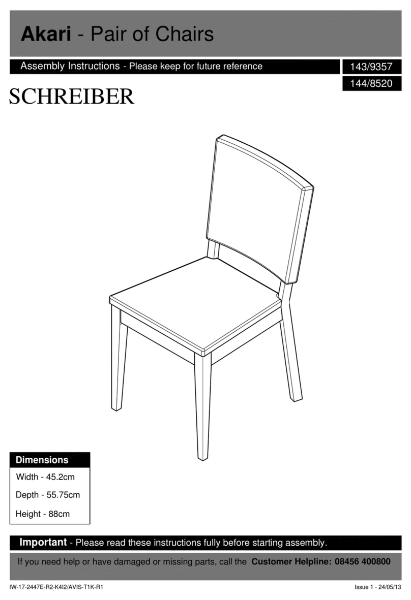
Argos Home Akari Pair of Chairs 143/9357 User manual

Argos Home

Argos Home Akari Pair of Chairs 143/9357 User manual

Argos Home Tongue & Groove 344/7794 User manual

Argos Home

Argos Home Tongue & Groove 344/7794 User manual

Argos Home Maddison Bunk 805/8906 User manual

Argos Home

Argos Home Maddison Bunk 805/8906 User manual

Argos Home 417/7317 Datasheet

Argos Home

Argos Home 417/7317 Datasheet

Argos Home Venice 403/7017 User manual

Argos Home

Argos Home Venice 403/7017 User manual

Argos Home 313/5226 User manual

Argos Home

Argos Home 313/5226 User manual

Argos Home New Hallingford 652/9482 User manual

Argos Home

Argos Home New Hallingford 652/9482 User manual

Argos Home Highsleeper Brooklyn 8545639 User manual

Argos Home

Argos Home Highsleeper Brooklyn 8545639 User manual

Argos Home Ipanema 458/7000 User manual

Argos Home

Argos Home Ipanema 458/7000 User manual

Argos Home Mia Single bed Hearts & Drw. White 2572141 User manual

Argos Home

Argos Home Mia Single bed Hearts & Drw. White 2572141 User manual

Argos Home Matrix Round Glass Lamp Table User manual

Argos Home

Argos Home Matrix Round Glass Lamp Table User manual

Argos Home Argos Home 625/9082 Datasheet

Argos Home

Argos Home Argos Home 625/9082 Datasheet

Argos Home Apartment Mirror 299/8426 User manual

Argos Home

Argos Home Apartment Mirror 299/8426 User manual

Argos Home Penton TV Unit 609/7093 User manual

Argos Home

Argos Home Penton TV Unit 609/7093 User manual

Argos Home Kent 275/8934 User manual

Argos Home

Argos Home Kent 275/8934 User manual
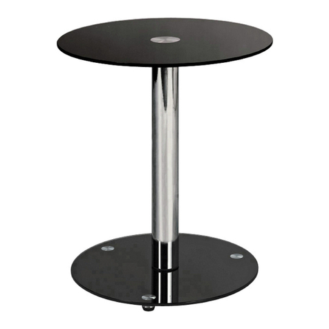
Argos Home Jorvic 620/5555 User manual

Argos Home

Argos Home Jorvic 620/5555 User manual

Argos Home Single Clothes Rail Heavy Duty 237/9375 User manual

Argos Home

Argos Home Single Clothes Rail Heavy Duty 237/9375 User manual

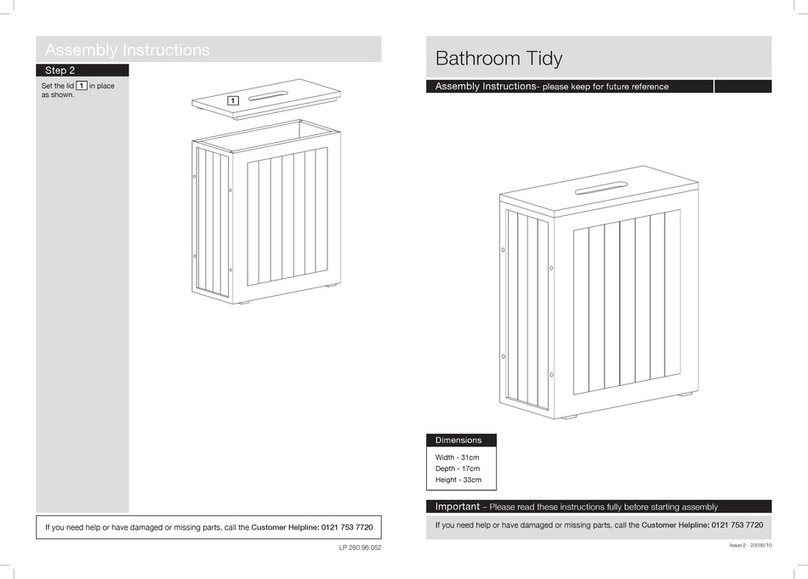
Argos Home hygena Matrix Round Glass Lamp Table User manual
Argos Home

Argos Home hygena Matrix Round Glass Lamp Table User manual

Argos Home 246/4675 User manual

Argos Home

Argos Home 246/4675 User manual

Argos Home Book Tidy 719/0023 Manual

Argos Home

Argos Home Book Tidy 719/0023 Manual

Argos Home 609/1295 User manual

Argos Home

Argos Home 609/1295 User manual

Argos Home Normandy 4 Drawer Chest of Drawers User manual

Argos Home

Argos Home Normandy 4 Drawer Chest of Drawers User manual

Argos Home 725/5573 User manual

Argos Home

Argos Home 725/5573 User manual

Popular Indoor Furnishing manuals by other brands

Regency LWMS3015 Assembly instructions

Regency

Regency LWMS3015 Assembly instructions

Furniture of America CM7751C Assembly instructions

Furniture of America

Furniture of America CM7751C Assembly instructions

Safavieh Furniture Estella CNS5731 manual

Safavieh Furniture

Safavieh Furniture Estella CNS5731 manual

PLACES OF STYLE Ovalfuss Assembly instruction

PLACES OF STYLE

PLACES OF STYLE Ovalfuss Assembly instruction

Trasman 1138 Bo1 Assembly manual

Trasman

Trasman 1138 Bo1 Assembly manual

Costway JV10856 manual

Costway

Costway JV10856 manual
moss DESIGN Caisson Credenza Assembly instructions

moss DESIGN

moss DESIGN Caisson Credenza Assembly instructions

Aquaglide FULL DECK 15.0 owner's manual

Aquaglide

Aquaglide FULL DECK 15.0 owner's manual

AREBOS AR-HE-SW30 user manual

AREBOS

AREBOS AR-HE-SW30 user manual

Till-Hilft Fulda 87005.330 Assembly instructions

Till-Hilft

Till-Hilft Fulda 87005.330 Assembly instructions

Twoey Outside 2010 quick start guide

Twoey Outside

Twoey Outside 2010 quick start guide

Hettich Easys 200 operating instructions

Hettich

Hettich Easys 200 operating instructions

The bedboss RELAX 404 Series owner's manual

The bedboss

The bedboss RELAX 404 Series owner's manual

Oeseder Möbelindustrie Bern 991 720 Assembly instructions

Oeseder Möbelindustrie

Oeseder Möbelindustrie Bern 991 720 Assembly instructions

Costway HW68469 user manual

Costway

Costway HW68469 user manual

Next ALIX A27743 Assembly instructions

Next

Next ALIX A27743 Assembly instructions

BROSA Hans Assembly guide

BROSA

BROSA Hans Assembly guide

Prodigg MINIKA PBA015T-FUR installation manual

Prodigg

Prodigg MINIKA PBA015T-FUR installation manual

manuals.online logo
manuals.online logoBrands
  • About & Mission
  • Contact us
  • Privacy Policy
  • Terms and Conditions

Copyright 2025 Manuals.Online. All Rights Reserved.