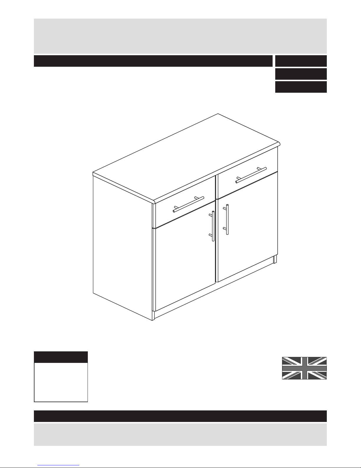
Argos Anderson 2 plus 2 Sideboard User manual
Other Argos Indoor Furnishing manuals

Argos
Argos 392/ 2068 User manual

Argos
Argos HOME Doublebed White 4Ft User manual

Argos
Argos 620/4721 User manual

Argos
Argos Solid Wood Linen Bin 8318471 User manual

Argos
Argos Verona 609/5057 User manual

Argos
Argos 609/2256 User manual

Argos
Argos Amersham 724/7196 User manual

Argos
Argos 044 0502 Series User manual

Argos
Argos Pagnell 709/2664 User manual

Argos
Argos PENTON User manual

Argos
Argos York 161/6297 User manual

Argos
Argos Luna hygena 457/7553 Datasheet

Argos
Argos 473/8639 User manual

Argos
Argos Aspley 497/6800 User manual

Argos
Argos Landon 241/7990 User manual

Argos
Argos Small Mustard Fabric Ottoman 716/5467 User manual

Argos
Argos 322/8645 User manual

Argos
Argos Arvika 356/4536 User manual

Argos
Argos Woburn 186/3215 User manual

Argos
Argos Tolga 323/6132 User manual


Popular Indoor Furnishing manuals by other brands


Coaster
Coaster 4799N Assembly instructions

Stor-It-All
Stor-It-All WS39MP Assembly/installation instructions

Lexicon
Lexicon 194840161868 Assembly instruction

Next
Next AMELIA NEW 462947 Assembly instructions

impekk
impekk Manual II Assembly And Instructions

Elements
Elements Ember Nightstand CEB700NSE Assembly instructions