manuals.online logo
Brands
  1. Home
  2. •
  3. Brands
  4. •
  5. Cognex
  6. •
  7. Machine Vision System
  8. •
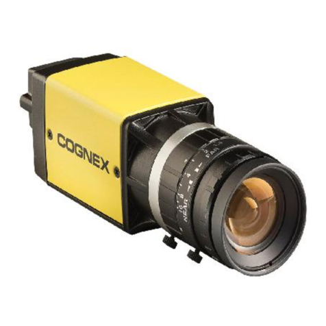
  9. Cognex In-Sight 2801 User manual

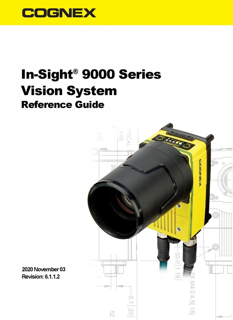
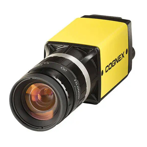
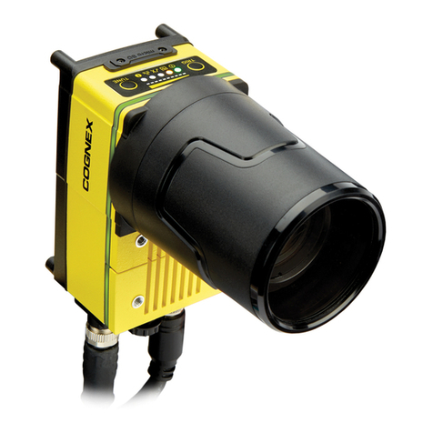
Cognex In-Sight 2801 User manual

In-Sight®2800 Series
Quick Reference Guide
2023 June 22
Revision: 23.1.1.16
Precautions
To reduce the risk of injury or equipment damage, observe the following
precautions when you install the Cognex product:
lConnectivity is possible through the following options:
l24 VDC (+/- 10%) output connection using a UL or NTRL listed
power supply
Any other voltage creates a risk of fire or shock and can damage the
components. Applicable national and local wiring standards and rules must
be followed.
lThis product is intended for industrial use in automated manufacturing or
similar applications.
lThe safety of any system incorporating this product is the responsibility of
the assembler of the system.
lDo not install Cognex products where they are exposed to environmental
hazards such as excessive heat, dust, moisture, humidity, impact,
vibration, corrosive substances, flammable substances, or static electricity.
lDo not expose the image sensor to laser light. Image sensors can be
damaged by direct, or reflected, laser light. If your application requires
laser light that might strike the image sensor, use a lens filter at the
corresponding laser wavelength. For suggestions, contact your local
integrator or application engineer.
lRoute cables and wires away from high-current wiring or high-voltage
power sources to reduce the risk of damage or malfunction from the
following causes: over-voltage, line noise, electrostatic discharge (ESD),
power surges, or other irregularities in the power supply.
2
lDo not expose the image sensor to laser light. Image sensors can be
damaged by direct, or reflected, laser light. If your application requires
laser light that might strike the image sensor, use a lens filter at the
corresponding laser wavelength. For suggestions, contact your local
integrator or application engineer.
lThis product does not contain user-serviceable parts. Do not make
electrical or mechanical modifications to product components.
Unauthorized modifications can void your warranty.
lChanges or modifications not expressly approved by the party responsible
for regulatory compliance could void the user’s authority to operate the
equipment.
lInclude service loops with cable connections.
lEnsure that the cable bend radius begins at least six inches from the
connector. Cable shielding can be degraded or cables can be damaged or
wear out faster if a service loop or bend radius is tighter than 10X the cable
diameter.
lThis device should be used in accordance with the instructions in this
manual.
lAll specifications are for reference purposes only and can change without
notice.
3
Symbols
The following symbols indicate safety precautions and supplemental information:
WARNING:This symbol indicates a hazard that could cause death, serious personal injury or
electrical shock.
CAUTION:This symbol indicates a hazard that could result in property damage.
Note: This symbol indicates additional information about a subject.
Tip: This symbol indicates suggestions and shortcuts that might not otherwise be apparent.
4
Accessories
You can purchase the following components separately. For a list of options and
accessories, contact your local Cognex sales representative.
Lenses
Accessory Product Number Illustration
12 mm Manual Focus Lens Module to be used with Multi Torch light 280-TORCH-
MAN12
16 mm Manual Focus Lens Module to be used with Multi Torch light 280-TORCH-
MAN16
Blue bandpass filter supported with IS2800 Mini with 6.2mm lens
illumination only
DM150-BP470
Blue bandpass filter, 450 nm 280-TORCH-
BP450
Red bandpass filter DM150-BP635
Red bandpass filter, 635 nm 280-TORCH-
BP635
5
Illumination
Accessory
Product
Number
Illustration
Red LED Light for 6.2 mm Lens (Risk Group Exempt acc. IEC 62471) DM150-
LED-RED
White LED Light for 6.2 mm Lens (Risk Group Exempt acc. IEC 62471) DM150-
LED-
WHT
Blue LED Light for 6.2 mm Lens (Risk Group Exempt acc. IEC 62471) DM150-
LED-BLU
High-Powered Red LED Light for 16 mm Lens (Risk Group Exempt acc. IEC
62471) For maximum light power 24 V DC supply is recommended.
280-LED-
REDHP
CAUTION:280-TORCH-MULTI devices equipped with a target aimer have
been tested in accordance with IEC60825-1 3rd ed., 2014., and have been
certified to be under the limits of a Class 2 Laser device.
6
Lens Covers
Accessory Product Number Illustration
Standard front cover. Use with a 6.2 mm lens only. DM280-CVR-62
Standard front cover, fully-polarized. Use with a 6.2 mm lens only. DM280-LENS-62CVR-F
Extended front cover. Use with a 16 mm lens only. DM260-LENS-16CVR
Extended front cover, half-polarized. Use with a 16 mm lens only. DM260-LENS-16CVR-P
Extended front cover, fully-polarized. Use with a 16 mm lens only. DM260-LENS-16CVR-F
Cross-polarized cover for Multi Torch 280-TORCH-COVPOL
Clear cover for Multi Torch 280-TORCH-COVCLR
Diffuse cover for Multi Torch 280-TORCH-COVDIF
CAUTION:For 280-TORCH-COVPOL, 280-TORCH-COVCLR, and 280-
TORCH-COVDIF equipped with a Time-of-Flight sensor, the device has been
tested to be under the limits of a Class 1 Laser device.
7
Mounting Brackets
Accessory Product Number Illustration
Universal mounting bracket DM100-UBRK-000
Pivot mounting bracket DM100-PIVOTM-01
Tilted angle pivot bracket DMBK-DMPIVOT-
00
Flat surface mounting plate adapter for Multi Torch
configuration 280-BKT-ADAPT
8
Cables
Note: Cables are sold separately.
Accessory Product Number Illustration
Ethernet Cable, X-coded M12-8 to
RJ-45
CCB-84901-2001-xx (straight, xx specifies length:
2m, 5m, 10m, 15m, 30m)
Ethernet Cable, X-coded M12-8 to
RJ-45
CCB-84901-2002-xx (right-angled, xx specifies
length: 2m, 5m, 10m)
Ethernet Cable, Robotic X-Coded
M12-8 to RJ-45
CCB-84901-2RBT-xx (straight, xx specifies length:
2m, 5m, 10m)
X-Coded to A-Coded Ethernet cable
adapter, 0.5 m
CCB-M12X8MS-XCAC
Power and I/O Breakout Cable, M12-
12 to Flying Lead
CCB-PWRIO- xx (straight, xx specifies length: 5m,
10m, 15m)
Power and I/O Breakout Cable, M12-
12 to Flying Lead
CCB-PWRIO-xxR (right-angled, xx specifies length:
5m, 10m, 15m)
I/O Module Cable M12-12 to DB15 CCB-PWRIO-MOD-xx (xx specifies length: 2m, 5m)
RS-232 Connection Cable CCB-M12xDB9Y-05
9
Accessory Product Number Illustration
I/O Extension Cable CKR-200-CBL-EXT
10
Setting Up Your In-Sight Vision System
Read this section to learn how the vision system connects to its standard
components and accessories.
Note:
lCables are sold separately.
lIf a standard component is missing or damaged, immediately contact
your Cognex Authorized Service Provider (ASP) or Cognex
Technical Support.
CAUTION:All cable connectors are keyed to fit the connectors on the vision
system. Do not force the connections or damage may occur.
Vision System Layout
The image and table below shows the elements of the vision system.
In-Sight 2800:
11
Number Description
1 Power I/O Breakout cable connector
2Ethernet connector
3Illumination LEDs
4 Trigger button
Note: The Trigger Button is not supported.
5 Tune button
Note: The Tune Button is not supported.
6Indicator LEDs
7Power LED indicator
8 Train status/Trigger status LED indicator
9 Good/bad inspection LED indicator
10 Communication LED indicator
11 Error LED indicator
12
Dimensions
The following sections list dimensions of the vision system.
Note:
lDimensions are in millimeters and are for reference purposes only.
lAll specifications are for reference purposes only and can change
without notice.
In-Sight 2800 Mini with 6.2 mm lens
The following image shows the dimensions of In-Sight 2800, equipped with 6.2 mm
lens.
13
In-Sight 2800 Mini with 16 mm Lens
The following image shows the dimensions of In-Sight 2800 equipped with 16 mm
lens.
14
In-Sight 2800 Mini with 6.2 mm Lens - Right Angle
Configuration
The following image shows the dimensions of In-Sight 2800 equipped with L-
shaped extension and 6.2 mm lens.
15
In-Sight 2800 Mini with 16 mm Lens - Right Angle
Configuration
The following image shows the dimensions of In-Sight 2800 equipped with L-
shaped extension and 16 mm lens.
16
In-Sight 2800 with Multi Torch
The following image shows the dimensions of In-Sight 2800 equipped with a Multi
Torch.
17
In-Sight 2800 with Multi Torch - Right Angle
Configuration
The following image shows the dimensions of In-Sight 2800 equipped with a Multi
Torch and L-shaped extension.
18
Field of View and Working Distance
This section provides the Field of View (FoV)values for the IS2800 with Multi Torch
and IS2800 Mini configurations. (On the diagrams, the values at the top are in mm
and the values at the bottom of the top values in the brackets are in inch).
In-Sight 2800 with Multi Torch and 12 mm Lens
Working Distance Horizontal FOV Vertical FOV
Minimum 50 mm (1.97 in) 16.8 mm (0.66 in) 12.6 mm (0.5 in)
20

This manual suits for next models

3

Other Cognex Machine Vision System manuals
Cognex In-Sight 7000 Gen2 Series User manual

Cognex

Cognex In-Sight 7000 Gen2 Series User manual

Cognex n-Sight 7802 User manual

Cognex

Cognex n-Sight 7802 User manual

Cognex In-Sight 5100 User manual

Cognex

Cognex In-Sight 5100 User manual

Cognex In-Sight 7800C User manual

Cognex

Cognex In-Sight 7800C User manual

Cognex In-Sight 8000 Series User manual

Cognex

Cognex In-Sight 8000 Series User manual

Cognex In-Sight 7000 Series Quick guide

Cognex

Cognex In-Sight 7000 Series Quick guide

Cognex In-Sight 7000 Series User manual

Cognex

Cognex In-Sight 7000 Series User manual

Cognex In-Sight 2000 User manual

Cognex

Cognex In-Sight 2000 User manual

Cognex In-Sight 9902L User manual

Cognex

Cognex In-Sight 9902L User manual

Cognex In-Sight EZ-700 Series User manual

Cognex

Cognex In-Sight EZ-700 Series User manual

Cognex In-Sight 7000 Series User manual

Cognex

Cognex In-Sight 7000 Series User manual

Cognex In-Sight 9000 Series User manual

Cognex

Cognex In-Sight 9000 Series User manual

Cognex In-Sight D900 Series User manual

Cognex

Cognex In-Sight D900 Series User manual

Cognex In-Sight 7000 Gen2 Series User manual

Cognex

Cognex In-Sight 7000 Gen2 Series User manual

Cognex In-Sight 7010 User manual

Cognex

Cognex In-Sight 7010 User manual

Cognex DataMan 360 Series User manual

Cognex

Cognex DataMan 360 Series User manual

Cognex In-Sight 1700 Series User manual
Cognex

Cognex In-Sight 1700 Series User manual

Cognex In-Sight 8000 Series User manual

Cognex

Cognex In-Sight 8000 Series User manual

Cognex In-Sight D900 Series User manual
Cognex

Cognex In-Sight D900 Series User manual

Cognex In-Sight 9902L User manual

Cognex

Cognex In-Sight 9902L User manual

Cognex In-Sight 8405 User manual

Cognex

Cognex In-Sight 8405 User manual

Cognex In-Sight 8200 User manual

Cognex

Cognex In-Sight 8200 User manual
Cognex In-Sight 5000 Series Installation and operating instructions

Cognex

Cognex In-Sight 5000 Series Installation and operating instructions

Cognex In-Sight 3D-L4000 Series User manual
Cognex

Cognex In-Sight 3D-L4000 Series User manual

Popular Machine Vision System manuals by other brands

Omron STC-APB503PCL Product specifications and user's guide

Omron

Omron STC-APB503PCL Product specifications and user's guide

CIS VCC-5CXP3R Product specification & operational manual

CIS

CIS VCC-5CXP3R Product specification & operational manual

Ark Vision Systems AVS-Monitor 7 FHD instruction manual

Ark Vision Systems

Ark Vision Systems AVS-Monitor 7 FHD instruction manual

SICK InspectorP61x operating instructions

SICK

SICK InspectorP61x operating instructions

THine THSEU101 user manual

THine

THine THSEU101 user manual

Nivisys DVS-110 Quick reference guide

Nivisys

Nivisys DVS-110 Quick reference guide

Omron FLV IR Series instruction sheet

Omron

Omron FLV IR Series instruction sheet

opto engineering LT2PR Series user manual

opto engineering

opto engineering LT2PR Series user manual

IMC Toys WALL-E Disney/Pixar Instructions for use

IMC Toys

IMC Toys WALL-E Disney/Pixar Instructions for use

NET Corsight CO1041C2 Operational manual

NET

NET Corsight CO1041C2 Operational manual

SVS-Vistek CoaXPress fxo540 manual

SVS-Vistek

SVS-Vistek CoaXPress fxo540 manual

SVS-Vistek hr387 Series manual

SVS-Vistek

SVS-Vistek hr387 Series manual

Safe Fleet 00-1109 R5 installation guide

Safe Fleet

Safe Fleet 00-1109 R5 installation guide

manuals.online logo
manuals.online logoBrands
  • About & Mission
  • Contact us
  • Privacy Policy
  • Terms and Conditions

Copyright 2025 Manuals.Online. All Rights Reserved.