ASA Electronics iN-Command JRVCS105 User manual

This guide ismade to ease troubleshooting the iN-Commandsystem. It willcover the
wiring code and where those wires are connected to the Body Control Module (BCM)
and Display Commander (DC), system functions, and what to lookfor to discern
where a problem could be.
JRVCS105 TROUBLESHOOTING GUIDE
Table of contents.........................................Page1
Keystone wiring code..................................Page2
Body Control Module wiring diagram.........Page 3
BCM Pin Values...........................................Page 4
Device Pairing & Functionality Testing........Page 5 - 10
Troubleshooting..........................................Page11 - 12
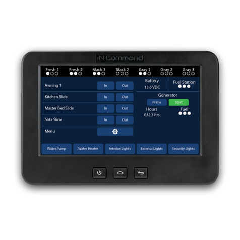
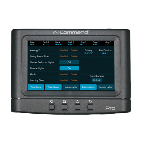
Display Commander (DC)
Body Control Module (BCM)
Page 1

Keystone 12 VDC Wire Standard
Page 2

BCM Pins 1-18 are on the Left side, ascending from Top to Bottom.
BCM Pins 19-36 on the Right side, ascending from Bottom to Top.
BCM Pins GND, RX, TX, and +12V DC (DC RX/TX wires) are at the Top Right
side.
Electric Wiring Guide for the BCM
Page 3

Pin NAME BCM FUNCTION NOTE A DMM
TANK LEVEL
0-.74V = EMPTY (○○○)
.75-1.74V= 1/3 (●○○)
1.75-3.59V = 2/3 (●●○)
3.6V = FULL (
●●●)
MEASURE FROM PIN 9 TO
EACH INPUT
1 FRESH 1 TANK IN 0-185KOHM
INPUT FROM SENDING UNIT SINGLE WIRE WORKS
ON RESISTANCE
VDC
2 BLACK 1 TANK IN 0-185KOHM
INPUT FROM SENDING UNIT SINGLE WIRE WORKS
ON RESISTANCE
VDC
3 BLACK 2 TANK IN 0-185KOHM
INPUT FROM SENDING UNIT SINGLE WIRE WORKS
ON RESISTANCE
VDC
4 GREY 1 TANK IN 0-185KOHM
INPUT FROM SENDING UNIT SINGLE WIRE WORKS
ON RESISTANCE
VDC
5 GREY 2 TANK IN 0-185KOHM
INPUT FROM SENDING UNIT SINGLE WIRE WORKS
ON RESISTANCE
VDC
6 GREY 3 TANK IN 0-185KOHM
INPUT FROM SENDING UNIT SINGLE WIRE WORKS
ON RESISTANCE
VDC
7 7 VDC COMMON OUTPUT TO TANK SENDING UNITS MEASURE FROM PIN 33 7VDC
TANK LEVEL
0-.74V = EMPTY (○○○)
.75-1.74V= 1/3 (●○○)
1.75-3.59V = 2/3 (●●○)
3.6V = FULL (
●●●)
MEASURE FROM PIN 9 TO
EACH INPUT
LIGHTING I/O
15A
8 LIGHT GROUP 12V 15A IN INPUT FROM MAIN BREAKER BOX 12VDC
9 LIGHT GROUP1 GND JUST A TERMINAL NO PCB TRACE NEEDED GND
10 LIGHT GROUP1 12V 15A OUT OUTPUT 12VDC FROM PIN 8 LIGHT IN 12V 12VDC
11 LIGHT GROUP2 GND JUST A TERMINAL NO PCB TRACE NEEDED GND
12 LIGHT GROUP2 12V 15A OUT OUTPUT 12VDC FROM PIN 8 LIGHT IN 12V 12VDC
13 AWNING LIGHT GND GND PASS THROUGH CONNECTION GND
14 AWNING LIGHT 12V 5A OUT POWER FROM 15A INPUT 12VDC
LIGHTING I/O
15A
Water Heater
15 +12V WATER HEATER FAULT IN RECEIVE 12V FAUILT SIGNAL 12VDC
16 WATER HEATER GND GND PASS THROUGH CONNECTION GND
17 WATER HEATER GAS +12V 1A OUT OUTPUT 12VDC TO GAS 12VDC
18
WATER HEATER ELECTRIC +12V 1A
OUT
OUTPUT 12VDC TO ELECTRIC 12VDC
TRAVEL LOCK 19 LOCKOUT SIGNAL IN 12V 12V INPUT FROM TOW VEHICLE BRAKE LOCK OUT SLIDES, JACKS &
AWNINGS WHEN PRESENT 12VDC
Water Heater
Water Pump
20 WATER PUMP +12V OUT 10A Output 12V to WATER PUMP 12VDC
21 WATER PUMP GND JUST A TERMINAL NO PCB TRACE NEEDED GND
22 WATER PUMP +12V IN 10A INPUT FROM MAIN BREAKER BOX 12VDC
Water Pump
AWNING
23 GND OUT (AWNING#1) OUTPUT 12V POWER & GROUND
REVERSING POLARITY DC
MOTOR
15A 12V/GND
24 12V OUT 15 AMP (AWNING#1) OUTPUT 12V GROUND & POWER
REVERSING POLARITY DC
MOTOR
12V/GND
30A
AWNING
Slides
25 GND OUT (SLIDE#4) OUTPUT 12V IN POWER & GROUND
REVERSING POLARITY DC
MOTOR
12V/GND
26 12V OUT 30 AMP (SLIDE#4) OUTPUT 12V IN GROUND & POWER
REVERSING POLARITY DC
MOTOR
12V/GND
27 GND OUT (SLIDE#3) OUTPUT 12V IN POWER & GROUND
REVERSING POLARITY DC
MOTOR
12V/GND
28 12V OUT 30 AMP (SLIDE#3) OUTPUT 12V IN GROUND & POWER
REVERSING POLARITY DC
MOTOR
12V/GND
29 GND OUT (SLIDE#2) OUTPUT 12V IN POWER & GROUND
REVERSING POLARITY DC
MOTOR
12V/GND
30 12V OUT 30 AMP (SLIDE#2) OUTPUT 12V IN GROUND & POWER
REVERSING POLARITY DC
MOTOR
12V/GND
31 GND OUT (SLIDE#1) OUTPUT 12V IN POWER & GROUND
REVERSING POLARITY DC
MOTOR
12V/GND
32 12V OUT 30 AMP (SLIDE#1) OUTPUT 12V IN POWER & GROUND
REVERSING POLARITY DC
MOTOR
12V/GND
Power
30A
Slides
33 CHASSIS GROUND GROUND GND
34 +12VDC IN ELECTRIC MOTOR FEED FROM BATTERY 30A 12VDC
35 +12 VDC IN BCM POWER FROM CONVERTER 15A 12VDC
36 EMPTY TERMINAL NONE
Power
BCM
Pin Values
Page 4

The BCM should be wired correctly, without loose connections, and +12 VDC connected at pin 35.
A RED LED will indicate that the BCM is powered and receiving 12 VDC. The DC is connected to the BCM with
4 wires in the upper right corner of the board: ground, receive, transmit, and 12 VDC power in (Gnd, RX, TX,
and +12VDC).
The toggle switch on the BCM corresponds to the dial underneath it. (In the event where communication
between the DC and BCM is lost or the DC is damaged, this switch will enable "manual" functions of the
selected devices) The switch and knob are used for Motors 1-5 (which could include slide outs, and awnings)
The DC will be mounted in a "all access" area near the entrance. On the DC, hold down the Power ( )
button for 5 seconds. After a moment,the Passcode Screen will appear. Enter your Passcode . If this is the
first time the DC has been powered on, an End User License Agreement (EULA)screen will appear. Upon
accepting the EULA, the Enter New Passcode screen will appear. Enter your new passcode twice.
Page 5

The DC will now bring up the Home Screen. If the Floor Plan has been loaded, all the available watertanks ,
battery voltage, and 3 "Hotkeys" will appear. The hotkeys will turn on the Water Pump, Water Heater, and
Interior lighting groups.
The DC has 4 physical buttons underneath the LCD Display. These are (from left to right) the Power, Pages,
Home, and Return buttons. To power on or off the DC, hold the Powerbutton down for 5 seconds. Touch the
power button, and the DC will activate (if powered on). The Pages button will cycle the pages on the DC;
from Home, to the Functions page, to the Menu page. The Return button will take you to the previous page.
Press the Pages button and observe the Functions Page. Here all the available functions for the RV will be
listed. Cycle each function and ensure it works smoothlyand corresponds to the correct device. Ensure all
the Home Screen "Hotkeys" actuate/turn on the corresponding devices.
Page 6

When turning on the Water Pump, open the Kitchen Faucet and listen for the pump to turn on. The Water
Pump is pressure controlled and will cycle based on demand. During this time the Water Pump button will
stay highlighted. The Interior Lights button will turn on all interior lights and stay highlighted when the lights
are on.
Pressing the "Pages" button a second time will take you to the Menu Page. The Buttons on top of the page
represent (from left to right): the Function List Menu, Connected Devices List, Bluetooth Menu, Password
Menu, Settings Menu, and Information Page .
Time to pair a device. Select the Bluetooth Menu ( ).
Selecting the Water Heater button will offer 3 settings: Electric, Propane, or Both. When the desired
selection is made, the Water Heater button's label will change to reflect the selection and stay highlighted.
Select the Water Heater button again to turn it off.
Page 7

The Pairing Screen will appear:
On the iOS Device, go to Settings and turn on Bluetooth.The iOS device will automaticallybegin broadcasting
a signal and it will show up in theUnpaired Devices list. Selectthe device. Onboth the iOS device and the DC,
a Pairing Request screen will appear. Accept the paring request. The DC will now be listed in the iOS Device's
Bluetooth menu (i.e.: JENSENDC05E1F7). Select the DC on the iOS device, it will show "Connected" on the
device's Bluetooth list, and the iOS device will show up in the DC's Paired Devices list. Now open the iN-
Command App on the device. It will pair and show the Home screen.
iOS (Apple) Device
Page 8

The Android Devices pair a little differently:
When the Pairing Screen is open on the DC, ensure that Bluetooth is functioning on the Android device, and
open the iN-Command App. Select the Menu button in the Android App and then the Bluetooth button. On
the DC press Discover and on the Android device press Scan. The BCM (i.e.: JENSENDC05E1F7) will show up in
the Android's Unpaired list. Select the DC. A Pairing Request will show up on the DC and the Android device,
accept both. The DC will now appear in the Android's Paired List with yellow font (indicating that it is Actively
paired with the DC. There can be more than 1 DC paired to a Android OR iOS device). Select the Home
button, the DC Pairing screen will appear, then the App will show the Home screen.
Android Device
The iOS and Android device Apps need to have the correct floorplan downloaded from the DC to display the
Trailer's functions. On either device (iOS or Android) go to the Settings screen and select the Reset button.
The Reset Menu will appear. Select Floorplan. The functions will populate on the App's Menu screen. Press
the Home button. Tank levels and Battery charge will be listed. Press the Function List button. The Functions
will be listed with an activation button next to them. The iOS or Android Device is now ready for use.
The iN-Command systemcan only be paired to 7 devices 4 Android and 3 iOS)and only 4 of them can be
active (3 Androids and 1 iOS). "Active" meaning they can activate functions and receive data. Apple
programming dictates that only 1 iOS device can be actively paired. To use another iOS device that is paired
to the iN-Command system,simply push the iOSApp's Power button and shut the App down.This will
disconnect thedevice from the BCM withouthaving to go to the iOS device's Bluetooth list and disconnecting
it. The new iOS device will need to have the DC selected in it's Bluetooth settings before opening the App.
3 Android devices are able to be actively paired at one time. If a user wishes to use the 4th paired Android
device, simply use the Power button on the device's App that the 4th device will be replacing. The Android
device will disconnectto allow the other device to be active.
Page 9

To verify that the Handheld device is connected to the DC, select the Interior Lights button. All the Interior
Lights should cycle with each button press and the corresponding buttons on the DC , and other devices,
should cycle from OFF to ON and vice versa.
Using the handheld device, cycle through all the functions previously tested on the DC. Ensure the DC display
correlates with thehandheld device's. While testingthe handheld device,push buttons on theDC. Lights
should function while using a Motor Function (slide, awning, etc.). Other Motor Functions should NOT be able
to actuate whilea MotorFunction is in use. A "SystemBusy "message shouldappear.
When connectingmultiple handheld devices,connection should be smooth,no other devicesshould be
kicked off, actuation of systems on one device should correspond to the buttons on other devices, and only
the non-motorized functions should be able to be actuated by any device while motorized functions are being
actuated on another.
Troubleshooting
Next, go to the ConnectedDevices List ( ).
The list should contain all Actively Paired devices with the option to "disconnect" them. Ensure the devices
can be disconnected.
Last, let's test the Lock Out feature. Apply +12 VDC to the Lock Out circuit by using a wire with clips.
Attach one end to Pin 35 and the other to Pin 19. This represents the driver of the tow vehicle stepping
on the brake. On the Home page, a Red button will appear with "Travel Lock " on it. All motorized
functions are now disabled, but the Hotkeysand lights will stillwork.
Carefully remove the wire attached to Pin 35 and Pin 19. The Red button on the DC's Home page will turn
light blue with "Unlock" written on it. To unlock the Travel Lock, this button on the DC must be selected.
the Travel Lock cannot be removed with a handheld device for safety reasons.
Page 10

Symptom Solution
Try cycling the DC with the Power button.
Check main fuse in Distribution Panel.
Press Reset button on BCM.
Check for 12V+ on +12VDC wire to DC using a
Digital Multi-meter.
Check ground wire connection to DC.
Try cycling power using the RV main breaker.
Check if the Red power LED is off,
Check the fuse in the Distribution Panel.
Check 12V+ on wire at pin 35.
Disconnect wire from pin 7, if BCM powers up,
there is a short on the wire. Correct wiring.
Check Ground wire at pin 33.
Disconnect and reconnect 12V+ and Ground
wires from the back of DC.
Cycle power to the BCM and DC.
Check wire connections to DC.
Ensure Battery is charged. Plug in shore power.
DC not controlling light or motor
functions, and DC is showing
0VDC
Swap the TX and RX wires either at the BCM or
back of the DC.
Electric motors do not move
Check for 12V+ at Pin 34. Ensure the relay
activates*.
Travel Lock is on
Ensure 12V+ is removed from pin 19. Press
Reset button
*Relay not activating
Replace the relay with one from an unused
circuit by gently pulling it off the board. Relay is
an automotive standard at 12VDC coil,
40/30Amp 14VDC contact
Display Commander (DC) will not
turn ON or no front panel operation
No power to the Body Control
Module (BCM), The Red Light is
off
DC screen flashing on and off after
installation
Troubleshooting
Troubleshooting The iN-Commandsystem is pretty painless. The BCM and DC simulate all the lights, gauges,
and switches on the old control panels. The BCM Pin Vales portion ofthis guide will clear mostissues.
Basically, if the BCM does not have the desired voltage, or signal input, it will not be able to function or read
tanks correctly. Also, if the BCM has the correct output voltage or signal , but nothing is functioning, the
problem lies in the wiring leading to the malfunctioningcomponent or thecomponent itself.
Any issues that are related to iN-Command that cannot be cleared using the above list will be tied to the
BCM and DC hardware and software. Careful inspection of the BCM will need to be done (possibly blowing
the BCM board with air to remove any dust ,debris ,or conductive material). If the BCM looks clean and
undamaged (without burnt or cracked components) with all the wires secure and not touching each other,
troubleshooting the program is needed.
Contact an ASA representative 1-877-845-8750for questions regarding iN-Command software or hardware
Page 11

Above is the Water tank sending unit. The sending unit runs on 7 VDC supplied by the BCM. The 7 VDC
signal runs to a sensor embedded into the side of the water tank. The 1/3, 2/3, and Full sensors are then
aligned in an ascending diagonal line from the 7 VDC sensor. The "To Tank Input" line runs to the BCM
and terminates at Pin s 1-7 depending on the tank. When water or waste starts to fill the tank, it contacts
the 7 VDC sensor and the 1/3, 2/3, and Full sensors. The Voltage travels through the 1/3, 2/3, and Full
sensor leads to a resistor bank, then out the red wire to the BCM. If the BCM is not receiving the correct
voltage (seen on Page 4 BCM Pin Values/Tank Levels in the Notes section) on Pins 1-7, it will not reflect
the correct tank level.
Should the incorrect voltage be coming from the tank, there could be debris on the sensor (for the Gray
and Black tanks) , the line to the 1/3, 2/3, or Full sensors are not terminated correctly, the sensorsare
not installed at the desired angle, or the sensor is bad.
Page 12
Other manuals for iN-Command JRVCS105
3
This manual suits for next models
1
Table of contents
Other ASA Electronics Control System manuals

ASA Electronics
ASA Electronics iN-Command Pro Plus JRVCS2 User manual

ASA Electronics
ASA Electronics iN-Command JRVCS105 User manual

ASA Electronics
ASA Electronics iN-Command JRVCS105 User manual

ASA Electronics
ASA Electronics iN-Command NCS40T User manual

ASA Electronics
ASA Electronics iN-Command JRVCS1 User manual

ASA Electronics
ASA Electronics JENSEN JRVCS1 User manual

ASA Electronics
ASA Electronics iN-Command JRVCS105 User manual