manuals.online logo
Brands
  1. Home
  2. •
  3. Brands
  4. •
  5. Asco
  6. •
  7. Control Unit
  8. •
  9. Asco RedHat 8314 Series Installation and operating instructions

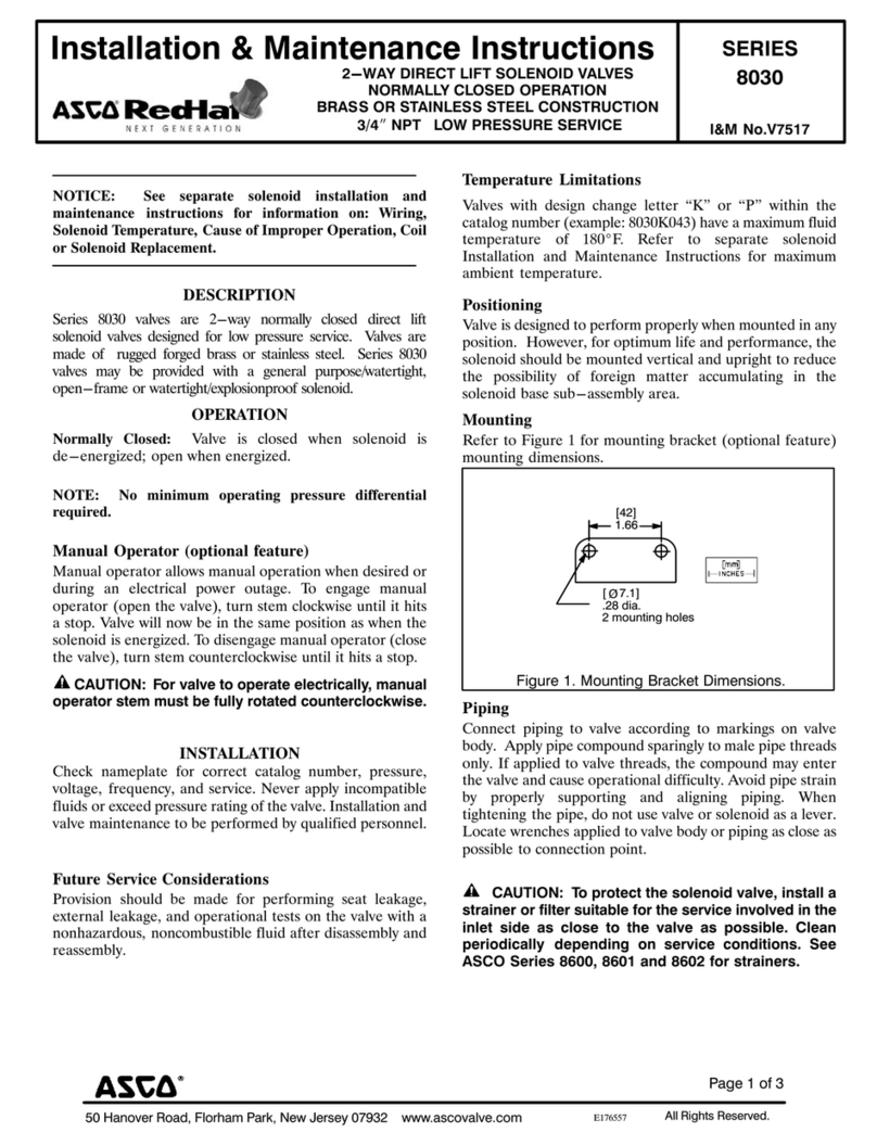
Asco RedHat 8314 Series Installation and operating instructions

Page 1 of 3
50 Hanover Road, Florham Park, New Jersey 07932 www ascovalve com All Rights Reserved
E176939
Installation & Maintenance Instructions SERIES
I&M No.V7533
8314NORMALLY O EN AND UNIVERSAL O ERATION
3/64I, 3/32I, 1/8I AND 5/32I ORIFICES
1/8I AND 1/4I N T
MIDGET 3-WAY SOLENOID VALVES NORMALLY CLOSED,
NOTICE: See separate solenoid installation and
maintenance instructions for information on: Wiring,
Solenoid Temperature, Cause of Improper Operation and
Coil Replacement.
DESCRIPTION
Series 8314 valves are midget 3-way solenoid valves . Valve bodies
are of brass constr ction. Series 8314 valves may be provided with a
general p rpose/watertight, open-frame or explosionproof/watertight
solenoid.
OPER TION
Normally Closed: Applies press re when solenoid is energized; exha sts
press re when solenoid is de-energized. Flow is Connection 2" to 1"
when solenoid is energized. Connection 3" is closed. Flow is from
Connection 1" to 3" when solenoid is de-energized. Connection 2"
is closed. Press re is applied at Connection 2".
Normally Open: Applies press re when solenoid is de-energized;
exha sts press re when solenoid is energized. Flow is Connection 1" to
2" when solenoid is energized. Connection 3" is closed. Flow is from
Connection 3" to 1" when solenoid is de-energized. Connection 2"
is closed. Press re is applied at Connection 3".
Universal: For normally closed or normally open operation, selection or
diversion of press re can be applied at Connections 1", 2" or 3". Flow
is between Connection 1" to 2" when solenoid is energized.
Connection 3" is closed. Flow is between Connection 1" to 3" when
solenoid is de-energized. Connection 2" is closed. Press re may be
applied at Connection 1", 2" or 3".
IMPORT NT: No minimum operating pressure differential
required.
DE-ENERGIZED
ENERGIZED
NORMALLY CLOSEDNORMALLY OPEN
DE-ENERGIZED
DE-ENERGIZED
ENERGIZEDENERGIZED
12
3
12
3
12
3
12
3
12
3
12
3
UNIVERSAL
PRESSURE ANY ORIFICE
Flow Diagram
INST LL TION
Check nameplate for correct catalog n mber, press re, voltage,
freq ency, and service. Never apply incompatible fl ids or exceed
press re rating of the valve. Installation and valve maintenance to be
performed by q alified personnel.
Temperature Limitations
Valves with design change letter K" or P" within the catalog n mber
(example: 8314K035) have a maxim m fl id temperat re of 180F.
Refer to separate solenoid Installation and Maintenance Instr ctions
for maxim m ambient temperat re.
Positioning
This valve is designed to perform properly when mo nted in any
position. However, for optim m life and performance, the solenoid
sho ld be mo nted vertically and pright to red ce the possibility of
foreign matter acc m lating in the solenoid base s b-assembly area.
Piping
Connect piping or t bing to valve according to markings on valve
body. Apply pipe compo nd sparingly to male pipe threads only. If
applied to valve threads, the compo nd may enter the valve and ca se
operational diffic lty. Avoid pipe strain by properly s pporting and
aligning piping. When tightening the pipe, do not se valve or
solenoid as a lever. Locate wrenches applied to valve body or piping
as close as possible to connection point.
IMPORT NT: To protect the solenoid valve, install a
strainer or filter, suitable for the service involved, in the inlet
side as close to the valve as possible. Clean periodically
depending on service conditions. See SCO Series 8600,
8601 and 8602 for strainers.
M INTEN NCE
WARNING: To prevent the possibility of
death, personal injury or property damage, turn
off electrical power, depressurize valve, and vent
fluid to a safe area before servicing the valve.
NOTE: It is not necessary to remove the valve from the pipeline for
repairs.
Cleaning
All solenoid valves sho ld be cleaned periodically. The time between
cleanings will vary depending on the medi m and service conditions. In
general, if the voltage to the coil is correct, sl ggish valve operation,
excessive noise or leakage will indicate that cleaning is req ired. In the
extreme case, fa lty valve operation will occ r and the valve may fail to
open or close. Clean valve strainer or filter when cleaning the valve.
Preventive Maintenance
Keep medi m flowing thro gh the valve as free from dirt and
foreign material as possible.
I&M No V7533
50 Hanover Road, Florham Park, New Jersey 07932 www ascovalve com
Page 2 of 3
Periodic exercise of the valve sho ld be considered if ambient or
fl id conditions are s ch that corrosion, elastomer degradation,
fl id contamination b ild p, or other conditions that co ld
impede solenoid valve shifting are possible. The act al freq ency
of exercise necessary will depend on specific operating conditions.
A s ccessf l operating history is the best indication of a proper
interval between exercise cycles.
Depending on the medi m and service conditions, periodic
inspection of internal valve parts for damage or excessive wear is
recommended. Thoro ghly clean all parts. If parts are worn or
damaged, install a complete reb ild kit.
Causes Of Improper Operation
Incorrect Pressure: Check valve press re. Press re to valve m st
be within range specified on nameplate.
Excessive Leakage: Disassemble valve and clean all parts. If parts
are worn or damaged, install a complete ASCO Reb ild Kit.
Valve Disassembly
1. Disassemble valve in an orderly fashion sing exploded views for
identification of parts.
2. Remove solenoid, see separate instr ctions.
3. Unscrew solenoid base s b-assembly and remove body gasket,
core assembly, core spring and core g ide (core g ide not
present on all constr ctions).
4. All parts are now accessible to clean or replace. Replace worn
or damaged parts with a complete ASCO Reb ild Kit.
Valve Reassembly
1. Reassemble valve sing exploded views for identification and
placement of parts.
2. L bricate solenoid base gasket with DOW CORNING 111
Compo nd l bricant or an eq ivalent high-grade silicone
grease.
3. Replace body gasket and install core assembly,core spring and
core g ide (if present) into solenoid base s b-assembly.
4. Replace solenoid base s b-assembly (with core assembly) into
valve body. Torq e solenoid base s b-assembly to 175$25
in-lbs. [19,8$2,8 Nm].
5. Install solenoid, see separate instr ctions and make electrical
connections.
WARNING: To prevent the possibility of
death, personal injury or property damage, turn
off electrical power, depressurize valve, and vent
fluid to a safe area before servicing the valve.
6. Restore line press re and electrical power s pply to valve.
7. After maintenance is completed, operate the valve a few times
to be s re of proper operation. A metallic click signifies the
solenoid is operating.
ORDERING INFORM TION
FOR SCO REBUILD KITS
Parts marked with an asterisk (*) in the exploded views are s pplied
in Reb ild Kits. When Ordering Reb ild Kits for ASCO valves,
order the Reb ild Kit n mber stamped on the valve nameplate. If the
n mber of the kit is not visible, order by indicating the n mber of kits
req ired, and the Catalog N mber and Serial N mber of the valve(s)
for which they are intended. [3,2]
125 R (4 places)
[Ø6,8]
266 dia
[22]
88
[15]
59
[17]
68
[22]
86
Mounting Bracket
59
69
1/4 NPT
1/8 NPT
[22,2]
[22,2]
875
875
brass & stainless steel
2 mounting holes 190-32
UNF-2B, 50 [12,7] deep
31 [7,9] min full thread
2 mounting holes 190-32
UNF-2B, 38 [9,7] deep
25 [6,4] min full thread
[15,1]
[17,5]
brass
1/8 NPT
stainless steel
[17]
688
190-32 UNF-2Bx 44 [11] deep
2 holes for mounting
[15,0]
592
Page 3 of 3
50 Hanover Road, Florham Park, New Jersey 07932 www ascovalve com
I&M No V7533
Torque Chart
art Name Torque Value Inch- ounds Torque Value Newton-Meters
solenoid base sub-assembly 175 ± 25 19,8 ± 2,8
Figure 1 Series 8314 valve without solenoid
solenoid base
sub-assembly
Indicates parts supplied
in ASCO Rebuild Kit
core assembly
core spring
valve body
(1/4 NPT Shown)
body gasket
mounting bracket
(1/4 NPT only)
core assembly
core spring
core guide
View showing core guide
(not present on all
constructions)

Other Asco Control Unit manuals

Asco 8210 series Installation and operating instructions

Asco

Asco 8210 series Installation and operating instructions

Asco 290 Series User manual

Asco

Asco 290 Series User manual

Asco 8214G54 Installation and operating instructions

Asco

Asco 8214G54 Installation and operating instructions

Asco 8401 Series User manual

Asco

Asco 8401 Series User manual

Asco 8215 Series Installation and operating instructions

Asco

Asco 8215 Series Installation and operating instructions

Asco 8042 Series Installation and operating instructions

Asco

Asco 8042 Series Installation and operating instructions

Asco FLOWTRONIC D 60701073 User manual

Asco

Asco FLOWTRONIC D 60701073 User manual

Asco RedHat 8223 Series Installation and operating instructions

Asco

Asco RedHat 8223 Series Installation and operating instructions

Asco 552 Series User manual

Asco

Asco 552 Series User manual

Asco 327 Series User manual

Asco

Asco 327 Series User manual

Asco MotorFlowD 610 Series User manual

Asco

Asco MotorFlowD 610 Series User manual

Asco 317 Series User manual

Asco

Asco 317 Series User manual

Asco 833-354 Series User manual

Asco

Asco 833-354 Series User manual

Asco 290 Series Instruction Manual

Asco

Asco 290 Series Instruction Manual

Asco JOUCOMATIC R294 Series User manual

Asco

Asco JOUCOMATIC R294 Series User manual

Asco 262 Series User manual

Asco

Asco 262 Series User manual

Asco RedHat 8321 Series Installation and operating instructions

Asco

Asco RedHat 8321 Series Installation and operating instructions

Asco 551 Series User manual

Asco

Asco 551 Series User manual

Asco 8040 Series Installation and operating instructions

Asco

Asco 8040 Series Installation and operating instructions

Asco 8320 Series Installation and operating instructions

Asco

Asco 8320 Series Installation and operating instructions

Asco 8314 Series Installation and operating instructions

Asco

Asco 8314 Series Installation and operating instructions

Asco 8316 Series User manual

Asco

Asco 8316 Series User manual

Asco Aseptic Positioner D Series Instruction Manual

Asco

Asco Aseptic Positioner D Series Instruction Manual

Asco 8345 Series Installation and operating instructions

Asco

Asco 8345 Series Installation and operating instructions

Popular Control Unit manuals by other brands

Viavi T-BERD MTS 5800 user manual

Viavi

Viavi T-BERD MTS 5800 user manual

Wiznet EG-SR-7100A user manual

Wiznet

Wiznet EG-SR-7100A user manual

KUHL Quantron E2 Original instructions

KUHL

KUHL Quantron E2 Original instructions

MD mXion KBM user manual

MD

MD mXion KBM user manual

Burkert 3364 operating instructions

Burkert

Burkert 3364 operating instructions

Yoshitake GD-26 Series product manual

Yoshitake

Yoshitake GD-26 Series product manual

Qu-Bit Electronix Data Bender quick start guide

Qu-Bit Electronix

Qu-Bit Electronix Data Bender quick start guide

Adeunis RF ARF54 user guide

Adeunis RF

Adeunis RF ARF54 user guide

Hubitron Steueungstechnik HBG 800-DP operating manual

Hubitron Steueungstechnik

Hubitron Steueungstechnik HBG 800-DP operating manual

Equinox Systems ISPnano I Series user manual

Equinox Systems

Equinox Systems ISPnano I Series user manual

HBX ZON-0550 installation manual

HBX

HBX ZON-0550 installation manual

BOC Edwards EXDC Series instruction manual

BOC Edwards

BOC Edwards EXDC Series instruction manual

Trimteck Optimux OpGL instruction manual

Trimteck

Trimteck Optimux OpGL instruction manual

Raychem TRACETEK TTC-1 Installation, operation and maintenance instructions

Raychem

Raychem TRACETEK TTC-1 Installation, operation and maintenance instructions

Motec Systems E888 user manual

Motec Systems

Motec Systems E888 user manual

rtd DM35820HR user manual

rtd

rtd DM35820HR user manual

Osaka PRO 08D Quick reference guide

Osaka

Osaka PRO 08D Quick reference guide

AQUATROL POWERFLO AQT-290 Service manual

AQUATROL

AQUATROL POWERFLO AQT-290 Service manual

manuals.online logo
manuals.online logoBrands
  • About & Mission
  • Contact us
  • Privacy Policy
  • Terms and Conditions

Copyright 2025 Manuals.Online. All Rights Reserved.