manuals.online logo
Brands
  1. Home
  2. •
  3. Brands
  4. •
  5. Asco
  6. •
  7. Control Unit
  8. •
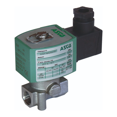
  9. Asco 8210 series User manual

Asco 8210 series User manual

Page 1 of 4
50 Hanover Road, Florham Park, New Jersey 0793 www.ascovalve.com
MM All Rights Reserved. Printed in U.S.A.
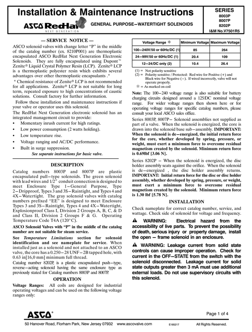
Installation & Maintenance Instructions SERIES
Form No.V5455R5
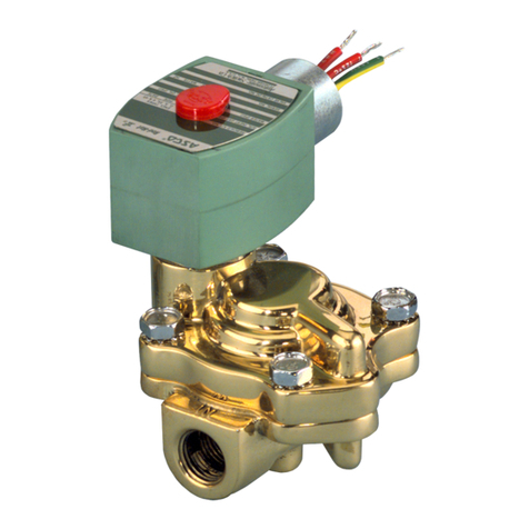
2-WAY INTERNA PI OTED-OPERATED SO ENOID VA VES 8210
BRASS AND STAIN ESS STEE CONSTRUCTION
NORMA Y C OSED OPERATION Ċ 1, 1 1/4, & 1 1/2 NPT
8211
NOTICE: See separate solenoid installation and maintenance
instructions for information on: Wiring, Solenoid Temperature,
Cause of Improper Operation, Coil or Solenoid Replacement.
DESCRIPTION
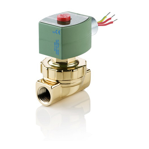
Series 8210 valves are 2-way normally closed internal
pilot-operated solenoid valves designed for general service. Valves
are made of rugged forged brass or stainless steel. Series 8210 valves
are provided with a general purpose solenoid enclosure.
Series E 8210 and 8211 are the same as Series 8210 except they are
provided with an explosionproof or explosionproof/watertight
solenoid enclosure.
OPER TION
Normally Closed: Valve is closed when solenoid is de-energized;
open when energized.
NOTE: No minimum operating pressure differential required.
Manual Operator (optional feature)
Manual operator allows manual operation when desired or during an
electrical power outage. To engage manual operator (open the valve),
remove operator cap and gasket base of valve. Turn manual operator
stem clockwise as far as possible. Do not force operator stem. Valve
will then be in the same position as when the solenoid is energized.
To disengage manual operator, turn stem counterclockwise as far as
possible.
CAUTION: Stem must be fully retracted counterclockwise
before operating valve electrically.
Replace manual operator cap gasket and cap.
INST LL TION
Check nameplate for correct catalog number, pressure, voltage,
frequency, and service. Never apply incompatible fluids or exceed
pressure rating of the valve. Installation and valve maintenance to be
performed by qualified personnel.
Future Service Considerations
Provision should be made for performing seat leakage, external
leakage, and operational tests on the valve with a nonhazardous,
noncombustible fluid after disassembly and reassembly.
Temperature Limitations
or maximum valve ambient and fluid temperatures, refer to chart
below. Check catalog number prefix and watt rating on nameplate.
Watt
Rating
AC/DC
Catalog
Number
Prefix
Coil
Class
Maximum
Ambient
Temp.
Maximum
Fluid
Temp.
15.1 & 16.1
None, KF,
SF or SC F 1 5F (51.7C) 180F (8 C)
AC HT, KH,
ST or SU H 140F (60C) 180F (8 C)
30.6
DC
HT H 104F (40C) 77F ( 5C)
Positioning
C Construction ( lternating Current): Valve is designed to
perform properly when mounted in any position. However, for
optimum life and performance, the solenoid should be mounted
vertical and upright so as to reduce the possibility of foreign matter
accumulating in the solenoid base sub-assembly area.
DC Construction (Direct Current): Valve must be mounted with
solenoid vertical and upright.
Piping
Connect piping to valve according to markings on valve body. Apply
pipe compound sparingly to male pipe threads only. If applied to
valve threads, the compound may enter the valve and cause
operational difficulty. Avoid pipe strain by properly supporting and
aligning piping. When tightening the pipe, do not use valve or
solenoid as a lever. Locate wrenches applied to valve body or piping
as close as possible to connection point.
CAUTION: To protect the solenoid valve, install a strainer
or filter suitable for the service involved in the inlet side as
close to the valve as possible. Clean periodically depending
on service conditions. See ASCO Series 8600, 8601 and 8602
for strainers.
M INTEN NCE
WARNING: To prevent the possibility of death,
serious injury or property damage, turn off electrical
power, depressurize valve, and vent fluid to a safe area
before servicing the valve.
NOTE: It is not necessary to remove the valve from the pipeline for
repairs.
Cleaning
All solenoid valves should be cleaned periodically. The time between
cleanings will vary depending on the medium and service conditions.
In general, if the voltage to the coil is correct, sluggish valve operation,
excessive noise or leakage will indicate that cleaning is required. In
the extreme case, faulty valve operation will occur and the valve may
fail to open or close. Clean strainer or filter when cleaning the valve.
Preventive Maintenance
Keep the medium flowing through the valve as free from dirt and
foreign material as possible.
While in service, the valve should be operated at least once a
month to insure proper opening and closing.
Depending on the medium and service conditions, periodic
inspection of internal valve parts for damage or excessive wear is
recommended. Thoroughly clean all parts. If parts are worn or
damaged, install a complete ASCO Rebuild Kit.
Causes of Improper Operation
Incorrect Pressure: Check valve pressure. Pressure to valve must
be within range specified on nameplate.
Excessive Leakage: Disassemble valve and clean all parts. If parts
are worn or damaged, install a complete ASCO Rebuild Kit.
50 Hanover Road, Florham Park, New Jersey 0793 www.ascovalve.com
Page of 4 Form No.V5455R5
Valve Disassembly
1. Disassemble valve in an orderly fashion using exploded views
for identification and placement of parts. Refer to igure 2
for AC construction; igure 3 for DC construction.
2. Remove solenoid enclosure. See separate instructions.
3. Unscrew solenoid base sub-assembly. or DC construction, a
special wrench is supplied in ASCO Rebuild Kit. or wrench
only, Order ASCO Wrench Kit No. K168146-001.
4. Remove bonnet screws, valve bonnet,bonnet gasket, spring
retainer (AC construction only) core spring, core/diaphragm
sub-assembly and body gasket.
5. or valves equipped with a manual operator, remove cap, cap
gasket, bonnet and bonnet gasket. Remove stem assembly with
stem gasket from bonnet.
6. All parts are now accessible for cleaning or replacement. If
parts are worn or damaged, install a complete ASCO Rebuild
Kit.
Valve Reassembly
1. Lubricate all gaskets and the disc at the base of the core
/diaphragm sub-assembly with DOW CORNING 111
Compound lubricant or an equivalent high-grade silicone
grease.
2. Replace body gasket and core/diaphragm sub-assembly.
Locate bleed hole in core/diaphragm sub-assembly directly
over valve outlet. or 1 1/2 NPT construction, locate bleed
hole in core/diaphragm sub-assembly approximately 30 from
valve outlet.
3. Replace core spring and spring retainer (AC construction
only). Install small end of core spring in core first, wide end
protruding from top of core. or DC construction, install
core spring, small end down toward valve body.
4. Replace valve bonnet and bonnet screws. Hand tighten bonnet
screws as far as possible.
IMPORT NT: Press firmly down on core/diaphragm
sub-assembly to seat diaphragm assembly against valve seat.
While holding this position, torque bonnet screws in a crisscross
manner to 144 ± 15 in-lbs [16,3 ± 1,7 Nm].
5. Replace bonnet gasket and solenoid base sub-assembly.
Torque solenoid base sub-assembly to 175 ± 25 in-lbs
[19,8 ± 2,8 Nm]. or DC construction, the solenoid base
sub-assembly must be placed inside the housing before
assembling into the valve body. Before doing this, read
separate lubrication instructions in Solenoid Installation &
Maintenance Instructions.
6. or valves provided with a manual operator, replace stem
assembly and bonnet (with gaskets). Torque bonnet to 75 ± 10
in-lbs [8,5 ± 1,1 Nm]. Replace cap gasket and cap.
7. Install solenoid. See separate instructions.
WARNING: To prevent the possibility of death,
serious injury or property damage, check valve for
proper operation before returning to service. Also
perform internal seat and external leakage tests with
a nonhazardous, noncombustible fluid.
8. Restore line pressure and electrical power supply to valve.
9. After maintenance is completed, operate the valve a few times
to be sure of proper operation. A metallic click signifies the
solenoid is operating.
ORDERING INFORM TION
FOR SCO REBUILD KITS
Parts marked with an asterisk (*) in the exploded view are supplied in
Rebuild Kits. When Ordering Rebuild Kits for ASCO valves, order
the Rebuild Kit number stamped on the valve nameplate. If the
number of the kit is not visible, order by indicating the number of kits
required, and the Catalog Number and Serial Number of the valve(s)
for which they are intended.
Torque Chart
Part Name Torque Value
Inch-Pounds
Torque Value
Newton-Meters
Manual
operator bonnet 75 ± 10 8,5 ± 1,1
Figure 1. Manual operator (optional feature)
valve
Indicates Parts Supplied
In ASCO Rebuild Kits
bonnet
stem
stem
bonnet
cap
cap
gasket
assembly
gasket
gasket
body
50 Hanover Road, Florham Park, New Jersey 0793 www.ascovalve.com
Page 3 of 4Form No.V5455R5
Torque Chart
Part Name Torque Value Inch-Pounds Torque Value Newton-Meters
Solenoid base sub-assembly 175 ± 5 19,8 ± ,8
Bonnet screw 144 ± 15 16,3 ± 1,7
Figure . Series 8 10 valve without solenoid (AC construction shown).
valve body
bonnet gasket
Indicates Parts Supplied
In ASCO Rebuild Kits
bonnet screw (4)
core/diaphragm
sub-assembly
body gasket
bleed hole
valve bonnet
solenoid base
sub-assembly
spring retainer
core spring
(small end in core first, wide
end protrudes from top of core)
1 and 1 1/4 NPT brass
construction shown
Locate bleed hole in
core/diaphragm sub-assembly
directly over outlet. For 1 1/ 
NPT construction locate bleed
hole 30 from valve outlet.
50 Hanover Road, Florham Park, New Jersey 0793 www.ascovalve.com
Page 4 of 4 Form No.V5455R5
Torque Chart
Part Name Torque Value Inch-Pounds Torque Value Newton-Meters
Solenoid base sub-assembly 175 ± 5 19,8 ± ,8
Bonnet screw 144 ± 15 16,3 ± 1,7
Figure 3. Series 8 10 valve without solenoid (DC construction shown).
solenoid base
sub-assembly
valve body
bonnet gasket
Indicates Parts Supplied
In ASCO Rebuild Kits
housing
bonnet screw (4)
core/diaphragm
sub-assembly
body gasket
bleed hole
valve bonnet
wrenching flats 1/  NPT conduit
connection
milled flats
for wrenching
Locate bleed hole in
core/diaphragm sub-assembly
directly over outlet. For 1 1/ 
NPT construction locate bleed
hole 30 from valve outlet.
Special wrench supplied
For wrench kit only
order No. K168146-001
1 and 1 1/4 NPT brass
construction shown
in ASCO Rebuild Kit.

This manual suits for next models

1

Other Asco Control Unit manuals

Asco 551 Series User manual

Asco

Asco 551 Series User manual

Asco RedHat 8314 Series Installation and operating instructions

Asco

Asco RedHat 8314 Series Installation and operating instructions

Asco 290 Series User manual

Asco

Asco 290 Series User manual

Asco JOUCOMATIC FLOWTRONICD 607 User manual

Asco

Asco JOUCOMATIC FLOWTRONICD 607 User manual

Asco 8267 Series Installation and operating instructions

Asco

Asco 8267 Series Installation and operating instructions

Asco Numatics 502 User manual

Asco

Asco Numatics 502 User manual

Asco Aseptic Positioner D Series Instruction Manual

Asco

Asco Aseptic Positioner D Series Instruction Manual

Asco 8320 Series Installation and operating instructions

Asco

Asco 8320 Series Installation and operating instructions

Asco 8262 series Installation and operating instructions

Asco

Asco 8262 series Installation and operating instructions

Asco 327 Series User manual

Asco

Asco 327 Series User manual

Asco 8345 Series Installation and operating instructions

Asco

Asco 8345 Series Installation and operating instructions

Asco 833-354 Series User manual

Asco

Asco 833-354 Series User manual

Asco 290 Series Instruction Manual

Asco

Asco 290 Series Instruction Manual

Asco 290 Series Instruction Manual

Asco

Asco 290 Series Instruction Manual

Asco 8317 Series Installation and operating instructions

Asco

Asco 8317 Series Installation and operating instructions

Asco 290 Series User manual

Asco

Asco 290 Series User manual

Asco 8222 Series Installation and operating instructions

Asco

Asco 8222 Series Installation and operating instructions

Asco 8342 series Instruction Manual

Asco

Asco 8342 series Instruction Manual

Asco 8003P Series Installation and operating instructions

Asco

Asco 8003P Series Installation and operating instructions

Asco FLOWTRONIC D 60701073 User manual

Asco

Asco FLOWTRONIC D 60701073 User manual

Asco 215 Series User manual

Asco

Asco 215 Series User manual

Asco 121 Series User manual

Asco

Asco 121 Series User manual

Asco 8344 Series User manual

Asco

Asco 8344 Series User manual

Asco 8551 Series Installation and operating instructions

Asco

Asco 8551 Series Installation and operating instructions

Popular Control Unit manuals by other brands

Weishaupt EM3/3 manual

Weishaupt

Weishaupt EM3/3 manual

Toshiba IK-CU51 instruction manual

Toshiba

Toshiba IK-CU51 instruction manual

ABB AC500 PLC Hardware manual

ABB

ABB AC500 PLC Hardware manual

GEA DHV DN65/50 KVS 16 operating instructions

GEA

GEA DHV DN65/50 KVS 16 operating instructions

Siemens SIJECT 16i Operation manual

Siemens

Siemens SIJECT 16i Operation manual

Teleco TVPLI868A01 manual

Teleco

Teleco TVPLI868A01 manual

Samoa 383 500 Service guide

Samoa

Samoa 383 500 Service guide

CTC Union 2216 installation guide

CTC Union

CTC Union 2216 installation guide

Fastech Ezi-STEP operating manual

Fastech

Fastech Ezi-STEP operating manual

Zano Controls GRID 1-10V quick start guide

Zano Controls

Zano Controls GRID 1-10V quick start guide

Siemens SINAMICS V60 Getting started

Siemens

Siemens SINAMICS V60 Getting started

Fireye MBCE-110FR manual

Fireye

Fireye MBCE-110FR manual

Pickering 40-785C user manual

Pickering

Pickering 40-785C user manual

Incam LCW-20P operation instruction

Incam

Incam LCW-20P operation instruction

Wiznet W7500S2E Series user manual

Wiznet

Wiznet W7500S2E Series user manual

Cooper Security i-on Series Engineering guide

Cooper Security

Cooper Security i-on Series Engineering guide

Swegon WISE Parasol Z b Series Instructions for use

Swegon

Swegon WISE Parasol Z b Series Instructions for use

BYD P6K Series INSTALLATION MANUAL AND USER MANUAL

BYD

BYD P6K Series INSTALLATION MANUAL AND USER MANUAL

manuals.online logo
manuals.online logoBrands
  • About & Mission
  • Contact us
  • Privacy Policy
  • Terms and Conditions

Copyright 2025 Manuals.Online. All Rights Reserved.