manuals.online logo
Brands
  1. Home
  2. •
  3. Brands
  4. •
  5. Asco
  6. •
  7. Control Unit
  8. •
  9. Asco 8316 Series Installation and operating instructions

Asco 8316 Series Installation and operating instructions

Page 1 of 4 E291076 - 07/2019 All Rights Reserved. I&M V_6592_CA
©ASCO Valve, Inc. 160 Park Avenue, Florham Park, New Jersey 07932 www.emerson.com
I&M V_6592_CA
Installation & Maintenance Instructions
3-WAY SOLENOID VALVES
NORMALLY CLOSED AND NORMALLY OPEN OPERATION
3/8” , 1/2” AND 3/4” NPT
SERIES
8316
NORMALLY OPEN
UNLATCHED
(CYL)
A
P
(PRESS)
LATCHED
(CYL)
A
E
(EXH)
P
(PRESS)
NORMALLY CLOSED
(CYL)
A
E
(EXH)
P
(PRESS)
LATCHED
(CYL)
A
E
(EXH)
P
(PRESS)
NOTICE: See separate solenoid installation and maintenance
instructions for information on: Wiring, Solenoid Temperature, Causes
of Improper Operation, and Coil Replacement.
DESCRIPTION
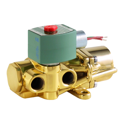
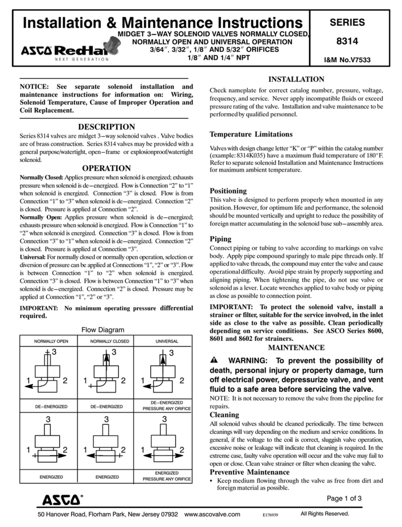
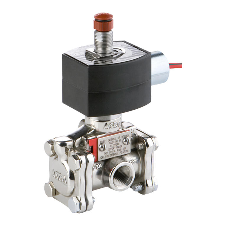
Series 8316 are 3-way, diaphragm-operated solenoid, pilot-controlled
valves. Valves are made of brass with only four moving parts: a core
assembly, two diaphragm assemblies and a disc holder sub-assembly.
Valves may be provided with a general purpose, explosionproof/watertight
solenoid enclosures.

dry inert gas and non-lubricated air service.
OPERATION
Normally Open
Solenoid De-energized: 



Normally Closed
Solenoid De-energized:



Flow Diagrams
IMPORTANT: A minimum operating pressure dierential of 10 psi is
required; however, valve vents to 0 psi.
Manual Operator
Manual operator allows manual operation when desired or during an
electrical power outage. To operate valve manually, rotate manual operator
stem clockwise 180
solenoid is energized. Rotate manual operator stem counterclockwise 180
before operating valve electrically.
INSTALLATION



personnel.
Temperature Limitations

or as limited by by hazardous location (explosive atmosphere) solenoid
       


8316nd 120

separate solenoid instruction sheet provided for ambient temperature.
Positioning
This valve is designed to perform properly when mounted in any position.
However, for optimum life and performance, the operator movement should
be mounted vertical and upright to reduce the possibility of foreign matter

in the catalog number must be mounted with the solenoid vertical and upright.
Mounting
Refer to Figure 1 for mounting bracket (optional feature) mounting
dimensions.
Piping

        
only. If applied to valve threads, the compound may enter the valve and
        
aligning piping. When tightening the pipe, do not use valve or solenoid as a
lever. Locate wrenches applied to valve body or piping as close as possible
to connection point.
To ensure proper operation of the valve,the pressure and exhaust lines must

on the nameplate must be maintained between pressure and exhaust at the

this minimum pressure during shifting. To check pressure during shifting,
install a pressure gauge in the pressure piping as close to the valve as possible.
IMPORTANT: To protect the solenoid valve, install a strainer or lter,
suitable for the service involved in the inlet side as close to the valve as
possible. Clean periodically depending on service conditions. See ASCO
Series 8600 and 8601 for strainers.
Flow Controls (Speed or Metering Devices)
Flow control valves may be added to control cylinder speed. If used, these

valve and the cylinder.
IMPORTANT: Do not install ow controls (speed or metering devices)
or any type of restrictive device in either the Pressure “P” (inlet) or
Exhaust “E” (outlet) ports of the valve. Restricting either of these lines
may cause valve malfunction.
MAINTENANCE
WARNING: To prevent the possibility of death,
personal injury or property damage, turn o󰀨 electrical
power, depressurize valve, and vent uid to a safe area
before servicing the valve.
AVERTISSEMENT: Pour éviter tous danger de mort,
de blessure grave ou de dommage matériel, avant
d’intervenir sur la vanne, couper le courant, purger la
vanne dans une zone sécurisée.

Cleaning
         
cleanings will vary depending on the medium and service conditions.
In general, if the voltage to the coil or solenoid is correct, sluggish valve

In the extreme case, faulty valve operation will occur and the valve may fail

Preventive Maintenance
• 
material as possible.
• While in service, the valve should be operated at least once a month to
ensure proper opening and closing.
• Depending on the medium and service condition, periodic inspection
of internal valve parts for damage or excessive wear is recommended.
Thoroughly clean all parts. If parts are worn or damaged, install a

UNLATCHED
E
(EXH)
Page 2 of 4 I&M No. V_6592_CA
©ASCO Valve, Inc. 160 Park Avenue, Florham Park, New Jersey 07932 www.emerson.com
Causes of Improper Operation
• Incorrect Pressure:       

• Excessive Leakage: Disassemble valve and clean all parts. If parts are

Valve Disassembly (Refer to Figures 1 and 2)
1. Disassemble valve in an orderly fashion. Use exploded views for

2. To remove valve solenoid, see separate solenoid instructions.
3. If the valve being serviced has a manual operator, refer to section

4. Unscrew solenoid base sub-assembly. Remove solenoid base gasket,
    

core spring and core guide.
5. 
self-tapping screw to remove insert from body. Turn screw a few turns

CAUTION: Do not damage center hole (pilot orice) in raised
surface insert. Remove insert by using a pair of pliers to grip the head
of the screw.
ATTENTION: N’endommager pas le trou central (orice
pilote) situé dans la partie haute de la pièce d’insertion. Retirez
la pièce d’insertion en utilisant une pince sur la tête de la vis.
6. Remove three gaskets from insert. Tag each gasket as it is removed so
that they can be reassembled in the same location. Middle and lower
gaskets are the same size. However, the lower gasket is a softer material.
Then remove disc holder sub-assembly, spring cup and disc spring.

7. The solenoid pilot is now completely disassembled.
8. Remove bonnet screws and lockwashers (4) from each end of valve
body. Remove valve bonnets, body passage gaskets, retaining rings,
diaphragm assemblies and body gaskets from each end of the valve
body. These parts are identical.
9.              

Valve Reassembly
1. 
of parts.
2.       

3.           
retaining ring, body passage gasket, valve bonnet and bonnet screws.
4. 
Nm].
5. 

been previously used.
6. Snap upper and middle insert gaskets into grooves of insert. Lower

and the lower corner of the body insert cavity. Middle and lower insert
gaskets are the same size. However, lower gasket is made of a softer
material.
7.   
and disc holder sub-assembly) into body cavity, making certain that the
disc holder spring is centered.
8. If the valve being rebuilt has a manual operator, refer to section on

9. Replace solenoid base gasket, core assembly, core spring and core guide,
if present. If the core spring is the internal type as shown in Figure 1, be

end of core spring protrudes from core top. If the core spring is the same
diameter throughout, the end with the closed turns will protrude from the
top of the core.
10.         

11. Install solenoid, see separate instructions, and make electrical hookup.
12. Restore line pressure and electrical power supply to valve.
13. 
of proper operation.
Manual Operator Disassembly
1. 
To determine correct manual operator construction, check valve
nameplate for watt rating. Then see Figure 2 for corresponding watt
rating.
2. Unscrew solenoid base sub-assembly. For valves with internal type
core springs, remove core spring, core assembly and solenoid base
gasket.
3. Unscrew manual operator body from main valve body and remove
body gasket.
4. Before removing the stem retainer from the manual operator body, note
the location of the captive spacer on the stem/lever sub-assembly. The
captive spacer will either be on the inside or outside of the fork on the
stem retainer. Location of this spacer is important for reassembly.
5. Remove stem retainer and slip the stem/lever sub-assembly from the
manual operator body. Then remove stem gasket from stem/lever sub-
assembly.
6. For valve with external type core springs, remove core assembly, core
spring, core guide and rider ring (if present). For valve with a watt
rating of 16.8; 6,;6.1; etc., remove disc holder sub-assembly.
7. 
Manual Operator Reassembly
1. Reassemble manual operator in reverse order of disassembly. Use
         

determine construction.
2. Replace body gasket and disc holder sub-assembly, if used.
3. Replace stem gasket on stem/lever sub-assembly.
4.        
assembly with stem gasket and stem retainer. On constructions with
an external type core springs, it is necessary to position (preassemble)
the core assembly in the manual operator body as part of the manual
operator body sub-assembly
5. There is a captive spacing washer on the stem/lever sub-assembly.
Referring to the full size template in Figure 2, locate the spacing washer
as follows:

dia.) or valves having a watt rating of 6; 6.1; etc., the spacer must be
located inside the retainer fork.

or valves having a watt rating of 16.8; 10.1; 11.2, etc., the spacer
must be located outside the retainer fork.
6. Install the stem/lever sub-assembly in manual operator body. Determine
the proper location of the spacer and slip the stem retainer in place.
7. For valves, with external type core springs, install core assembly with
core spring, core guide and rider ring (if present) into base of manual
operator body. For valves with internal type core spring, install disc
holder sub-assembly into base of manual operator body.
8. 

9. 
position that the operator would be in if the valve was to be operated
electrically.
10. Install core assembly, core spring, solenoid base gasket and solenoid


11. Install the solenoid and make electrical hookup
12. Restore line pressure and electrical power supply.
13.         
manually a few times to be sure of proper operation.
ORDERING INFORMATION
FOR ASCO REBUILD KITS


Rebuild Kit number stamped on the valve nameplate. If the number of
the kit is not visible, order by indicating the number of kits 

they are intended.
Page 3 of 4 I&M No. V_6592_CA
©ASCO Valve, Inc. 160 Park Avenue, Florham Park, New Jersey 07932 www.emerson.com
    

  

        
Page 4 of 4 I&M No. V_6592_CA
©ASCO Valve, Inc. 160 Park Avenue, Florham Park, New Jersey 07932 www.emerson.com
     

  

        

Other manuals for 8316 Series

2

Other Asco Control Unit manuals

Asco 8344 Series User manual

Asco

Asco 8344 Series User manual

Asco 8210 series User manual

Asco

Asco 8210 series User manual

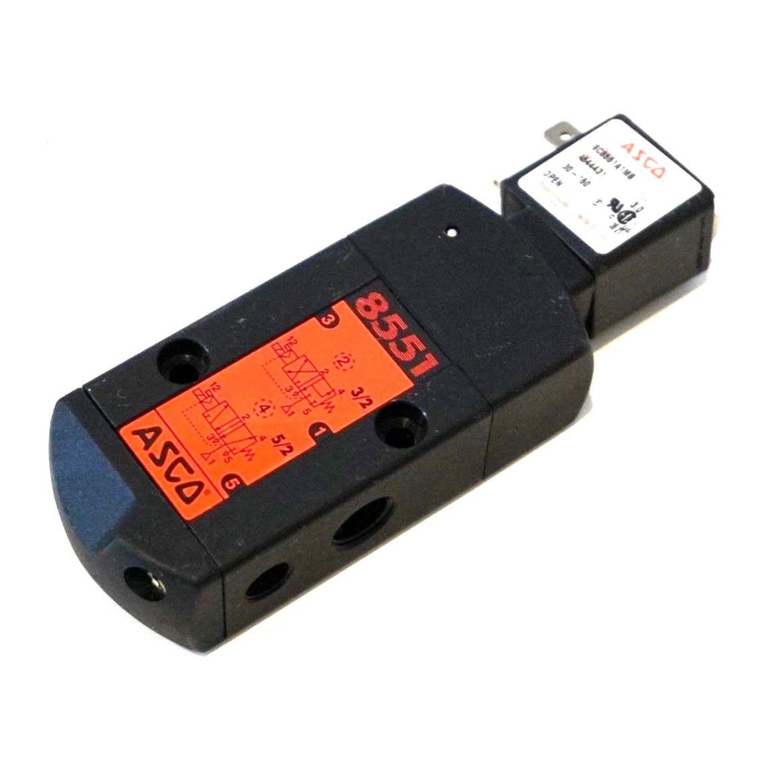
Asco 8551 Series Installation and operating instructions

Asco

Asco 8551 Series Installation and operating instructions

Asco Numatics 502 User manual

Asco

Asco Numatics 502 User manual

Asco 551 Series User manual

Asco

Asco 551 Series User manual

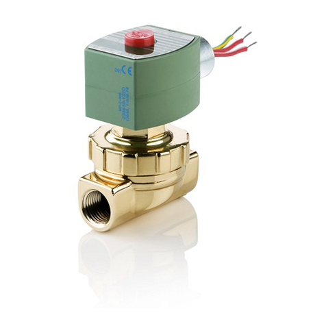
Asco RedHat 8223 Series Installation and operating instructions

Asco

Asco RedHat 8223 Series Installation and operating instructions

Asco 8030 Series Installation and operating instructions

Asco

Asco 8030 Series Installation and operating instructions

Asco 8316 Series Installation and operating instructions

Asco

Asco 8316 Series Installation and operating instructions

Asco 290 Series User manual

Asco

Asco 290 Series User manual

Asco 8314 Series Installation and operating instructions

Asco

Asco 8314 Series Installation and operating instructions

Asco 290 Series User manual

Asco

Asco 290 Series User manual

Asco JOUCOMATIC SENTRONIC 601 Series User manual

Asco

Asco JOUCOMATIC SENTRONIC 601 Series User manual

Asco 8040 Series Installation and operating instructions

Asco

Asco 8040 Series Installation and operating instructions

Asco 8210 series Installation and operating instructions

Asco

Asco 8210 series Installation and operating instructions

Asco 8342 series Instruction Manual

Asco

Asco 8342 series Instruction Manual

Asco 8262 series Installation and operating instructions

Asco

Asco 8262 series Installation and operating instructions

Asco JOUCOMATIC R294 Series User manual

Asco

Asco JOUCOMATIC R294 Series User manual

Asco 552 Series User manual

Asco

Asco 552 Series User manual

Asco 8316 Series User manual

Asco

Asco 8316 Series User manual

Asco 8210 Series Installation and operating instructions

Asco

Asco 8210 Series Installation and operating instructions

Asco 302 Series User manual

Asco

Asco 302 Series User manual

Asco RedHat  8317 Series Installation and operating instructions

Asco

Asco RedHat 8317 Series Installation and operating instructions

Asco 298 Series User manual

Asco

Asco 298 Series User manual

Asco 290 Series User manual

Asco

Asco 290 Series User manual

Popular Control Unit manuals by other brands

Niko 340-00111 manual

Niko

Niko 340-00111 manual

Flomatic Comboair installation instructions

Flomatic

Flomatic Comboair installation instructions

Nordson EFD 736HPA Maintenance & Parts Guide

Nordson EFD

Nordson EFD 736HPA Maintenance & Parts Guide

elsner elektronik IMSG 230 compact Technical specifications and installation instructions

elsner elektronik

elsner elektronik IMSG 230 compact Technical specifications and installation instructions

CALEFFI 510 Series quick start guide

CALEFFI

CALEFFI 510 Series quick start guide

Chroma Uploader II quick start guide

Chroma

Chroma Uploader II quick start guide

HKS Super SQV IV 71008-AK001 manual

HKS

HKS Super SQV IV 71008-AK001 manual

Niobrara QUCM 3964 Installation and programming manual

Niobrara

Niobrara QUCM 3964 Installation and programming manual

WEG DBW03 Series user manual

WEG

WEG DBW03 Series user manual

EOS ECON A2 Installation and user manual

EOS

EOS ECON A2 Installation and user manual

ExTox ET-1D Series instruction manual

ExTox

ExTox ET-1D Series instruction manual

Huawei MU509-b Application guide

Huawei

Huawei MU509-b Application guide

Spirax Sarco 5953 Series Installation and maintenance instructions

Spirax Sarco

Spirax Sarco 5953 Series Installation and maintenance instructions

H3C PSR450-12A user manual

H3C

H3C PSR450-12A user manual

Seraphim SRP-XXX-6PA-BB installation guide

Seraphim

Seraphim SRP-XXX-6PA-BB installation guide

Parker Racor RK19506 instructions

Parker

Parker Racor RK19506 instructions

Festo CDVI5.0 Assembly instructions

Festo

Festo CDVI5.0 Assembly instructions

Bartec APEX px operating instructions

Bartec

Bartec APEX px operating instructions

manuals.online logo
manuals.online logoBrands
  • About & Mission
  • Contact us
  • Privacy Policy
  • Terms and Conditions

Copyright 2025 Manuals.Online. All Rights Reserved.