TD 92724EN
20 May 2015/ Ver. D
Installation Guide
CR4 and CR6 Battery Pack Charger for Ascom
2
1. Introduction
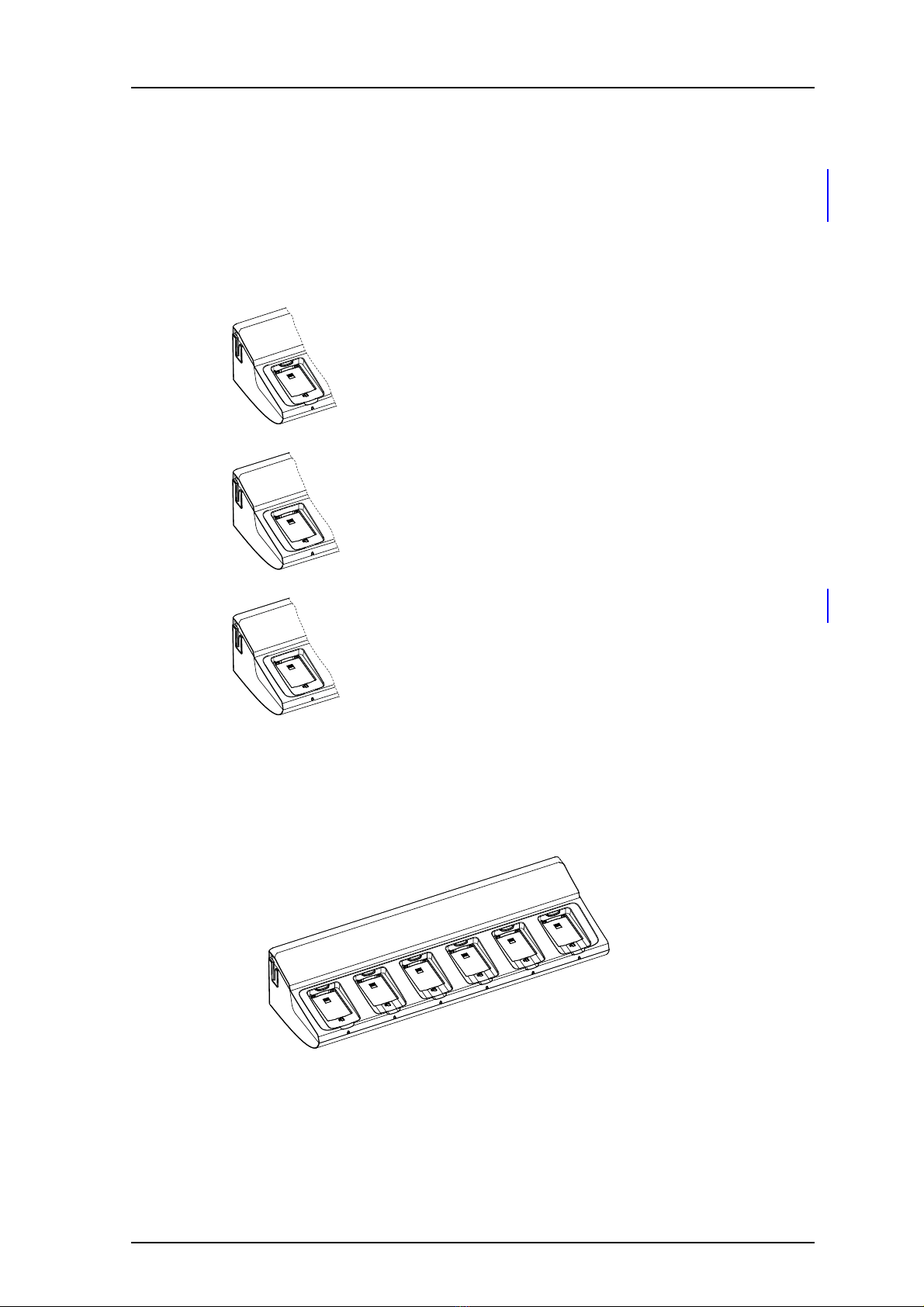
Single Unit
The Battery Pack Charger can be installed as a single unit.
Multiple Units
A number of Battery Pack Chargers and Charging Racks may be connected together.
Maximum five units may be connected. An installation with multiple units requires a fixed
electrical installation.
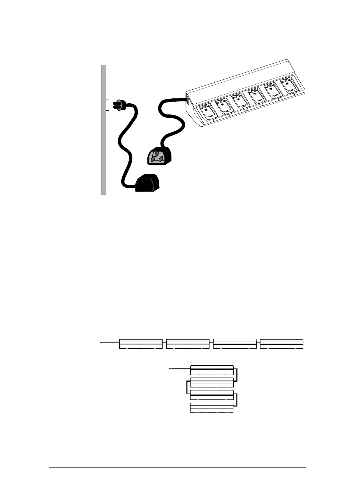
NOTE: In the USA and Canada the Battery Pack Charger must only be installed as a single
unit. Connection of several units is not permitted.
1.1 Safety
•It is not allowed to supply more than one unit by the power cord with the C14 connector.
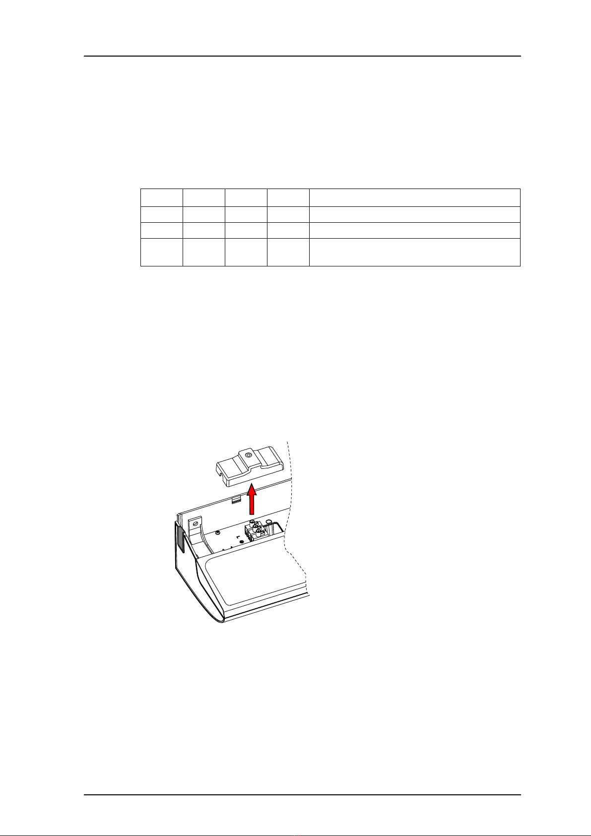
• The safety covers on top of the supply voltage terminal blocks must be mounted to
prevent hazardous situations, like electric shock.
• When servicing the unit, the power cord must be disconnected.
• For permanently connected equipment, a readily accessible disconnect device shall be
incorporated in the building installation wiring. The disconnect device shall disconnect
both poles.
• For pluggable equipment, the wall outlet shall be installed near the equipment and shall
be easily accessible.
In Sweden, Norway and Finland the unit must be connected to protective earth (safety
grounding). For other countries it is recommended to use a protective earth connection.
• Suomi: Laite on liitettävä suojamaadoituskoskettimilla varustettuun pistorasiaan.
• Norge: Apparatet må tillkoples jordet stikkontakt.
• Sverige: Apparaten skall anslutas till jordat uttag.
1.2 Regulatory Compliance Statements (EU and EFTA only)
This equipment is intended to be used in the whole EU & EFTA.
This equipment is in compliance with the essential requirements and other relevant
provisions of R&TTE Directive 1999/5/EC. The Declaration of Conformity may be consulted
at:
http://www.ascom.com/ws/products_ws.htm
The product is marked with .
1.3 Regulatory Compliance Statements (USA and Canada only)
FCC Compliance Statements for USA
This equipment has been tested and found to comply with the limits for a Class B digital
device, pursuant to part 15 of the FCC Rules. These limits are designed to provide reasonable
protection against harmful interference in a residential installation. This equipment
generates, uses and can radiate radio frequency energy and, if not installed and used in
accordance with the instructions, may cause harmful interference to radio communications.
However, there is no guarantee that interference will not occur in a particular installation. If
this equipment does cause harmful interference to radio or television reception, which can