Asko DC 7181 User manual

ASKO DC 7181
Use & Care Guide
Drying cabinet
Save these instructions for future reference

Dear ASKO customer!
Congratulations on your excellent product choice and welcome to the Asko
family. A global family with its roots in Scandinavia.
Good results, design, low environmental impact (both on nature and in your
home), user-friendliness, low consumption of time, energy and water, long
service life, reliability.... Good appliances should include all of these. And this
is what we try to give you.
When you buy an ASKO product, we want you to feel assured that the inside
is as good as the outside, and that the ethics and morals on which we built this
machine are just as high as the quality and performance you get from it. That
is what Scandinavian quality is all about.
In order to get the best possible results from your drying cabinet, please read this
manual before using the appliance. And if you have any questions, please do not
hesitate to contact us by the phone or via our website.
Best regards from Scandinavia and the people at Asko.

3
Customer Care Center 1-800-898-1879 www.askousa.com
Date: November 2006
The contents of this user manual describe the
drying cabinet’s:
Function
Use
This user manual
Contents
and contains instructions for:
Installation
Maintenance
Important safety instructions . . . . . . . . 4
Symbols . . . . . . . . . . . . . . . . . . . . . 4
Important safety information . . . . . . 4
Description of the drying cabinet . . . . 5
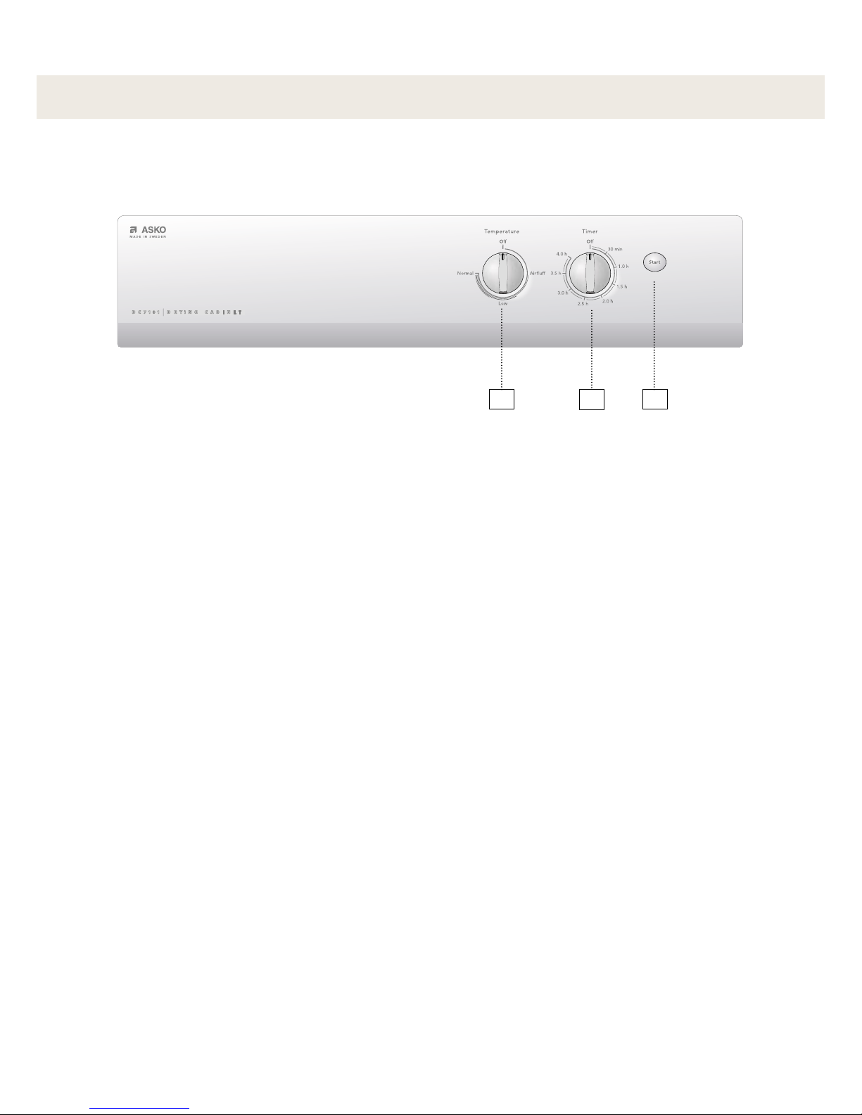
Control panel . . . . . . . . . . . . . . . . . . . . . 6
Location requirements . . . . . . . . . . . . . 7
Electrical requirements . . . . . . . . . . . . . 8
User liability. . . . . . . . . . . . . . . . . . . 8
Electrical connection . . . . . . . . . . . . 8
Grounding instructions . . . . . . . . . . 8
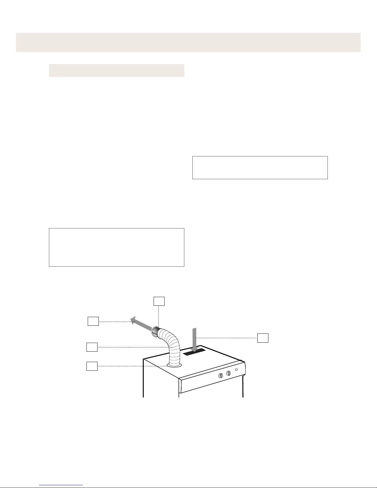
Ventilation requirements . . . . . . . . . . . . 9
Ventilation out into the room where
the drying cabinet is located . . . . . . 9
Connection to a vent duct . . . . . . . 10
Installation instructions . . . . . . . . . . . 12
Unpacking drying cabinet . . . . . . . 12
A complete delivery includes . . . . 12
Recommended tools . . . . . . . . . . . 12
Assembly kit . . . . . . . . . . . . . . . . . 13
Reverse door swing . . . . . . . . . . . . 14
Level drying cabinet . . . . . . . . . . . 15
Attaching drying cabinet to wal
l . . . . 15
Mounting into custom cabinetry
. . . . 16
Ventilation connection . . . . . . . . . . 18
Electrical connection . . . . . . . . . . . 18
Final inspection . . . . . . . . . . . . . . . 19
Operation instructions . . . . . . . . . . . . 20
Starting your drying cabinet . . . . . 20
Pausing or restarting. . . . . . . . . . . 20
Stopping your drying cabinet . . . . 20
Loading . . . . . . . . . . . . . . . . . . . . . 20
Cycle and drying tips. . . . . . . . . . . 21
Cycles . . . . . . . . . . . . . . . . . . . . . . 22
Care . . . . . . . . . . . . . . . . . . . . . . . . . . . . 23
Cleaning the drying cabinet . . . . . 23
When the drying cabinet is not in
use . . . . . . . . . . . . . . . . . . . . . . . . 23
Troubleshooting . . . . . . . . . . . . . . . . . . 24
Service and Warranty . . . . . . . . . . . . . 25
Technical data . . . . . . . . . . . . . . . . . . . 27
Technical characteristics . . . . . . . . 27
Exhaust . . . . . . . . . . . . . . . . . . . . . 27
Energy consumption and drying
times . . . . . . . . . . . . . . . . . . . . . . 27
Manufacturing standards . . . . . . . . 27
Installation spacing for custom
cabinetry . . . . . . . . . . . . . . . . . . . . 27
Personal notes . . . . . . . . . . . . . . . . . . . 28

4Customer Care Center 1-800-898-1879 www.askousa.com
Important safety instructions
Read this manual carefully and follow the
provided instructions.
Indicates risk for injury (including
fatal injury) or serious damage to the
product if the instructions are not
observed.
Warning! Advice and instructions for how the
product is best used for problem-free
operation
Important safety information
The following advice and warnings are in-
cluded to help you avoid incorrect operation
and unnecessary risks for accidents. You must
therefore read the manual carefully prior to
installation and use of the drying cabinet.
Read this user manual prior to operating
the drying cabinet.
Do not dry clothing or similar articles that
have recently been subjected to gasoline
or other volatile and flammable liquids. This
can result in the formation of an explosive
gas mixture.
Do not allow children to play in or on the
drying cabinet. Keep an eye on children
close to the drying cabinet.
The drying cabinet is to be installed or
stored indoors.
Follow Asko’s instructions when making
repairs or replacing parts.
If softeners or anti-static agents are used,
follow the manufacturer’s instructions for
use.
Never use heat in the cabinet for products
that contain foam rubber or similar mate-
rials. Carefully follow the manufacturer’s
instructions for washing and drying of such
products.
Keep the area around the outlet duct free
from dust and dirt.
Periodically clean the inside of the drying
cabinet.
Always keep this manual accessible for
future reference.
Symbols
This manual does not cover every
possible conditions and situation that
can occur. Use common sense and
caution when installing, operating, and
maintaining any appliance.

5
Customer Care Center 1-800-898-1879 www.askousa.com
DC XXXX
1
2
3
4
5
6
7
8
11
12
13
10
9
Description of the drying cabinet
1. Exhaust collar
2. Drying cabinet model
3. Hanger hooks
4. Rating plate (inside)
5. Upper hanger section
6. Middle hanger section
7. Lower hanger section
8. Shoe rack (optional)
9. Air intake
10. Control panel
11. Door
12. Door hanger for lighter articles
13. Glove hanger

6Customer Care Center 1-800-898-1879 www.askousa.com
123
D C 7 1 8 1 D R Y i N G C A B I N E T
Control panel
1. Temperature setting
2. Timer
3. START button

7
Customer Care Center 1-800-898-1879 www.askousa.com
23 7/16” (59.5 cm)
72 7/16” (184.0 cm)
25 1/4” (64.0 cm)
24” (61.0 cm)
Location requirements
If the drying cabinet is to be installed with
a connection to exhaust air ventilation,
this must be available on the premises.
A grounded electrical outlet must be
within 79 in. (2 meters) of the drying
cabinet’s upper section. A 79-in. (2-me-
ter) grounded power cord with a plug is
connected at the top of the drying cabi-
net. If the electrical outlet is not located
as above, the location must be adjusted
so that an extension cord is not neces-
sary.
The electrical outlet shall be easily ac-
cessible after installation of the drying
cabinet. Take this into consideration even
in cases when the drying cabinet is built
into custom cabinetry or similar framing.
For further information, see the section
“Electrical requirements”.
The floor must be able to support the
weight of the cabinet 133 lbs (60 kg).
The floor must be flat with a slope under
the cabinet of no more than 1 in. (2.5
cm).
The drying cabinet is only intended for
installation indoors and at temperatures
above 0°C (32°F).
The drying cabinet may not be located in
environments where pressurized water
is used for cleaning.
Installation dimensions

8Customer Care Center 1-800-898-1879 www.askousa.com
Electrical requirements
Risk for electrocution
Connect to grounded wall outlet
Do not remove ground connection
Do not use an adapter
Do not extend the cord
Failure to observe the above entails
risk for serious injury or fire.
Warning!
Electrical connection
The drying cabinet must be connected to
a 120 V, single-phase, 60 Hz grounded
wall outlet.
The drying cabinet is delivered ready for
connection with a 79-in. (2-meter) power
cord with a grounded plug.
The drying cabinet is to be connected
with the supplied power cord to a ground-
ed wall outlet and may not be wired to
terminals.
The electrical outlet shall be located so
that the power plug can be easily un-
plugged without moving the unit.
Check that the power source is in agree-
ment with the data on the rating plate
and that the wiring is properly grounded
in compliance with applicable standards.
We recommend that the wiring be in-
stalled with a circuit breaker.
The connection shall be separately
fused.
The manufacturer bears no liability if
the electrical connection is not made as
specified in this user manual.
User liability
It is the responsibility of the user to contact an
authorized electrician if an electrical outlet in
compliance with this manual is unavailable.
Grounding instructions
This drying cabinet must be properly ground-
ed. In the event of malfunction or breakdown,
grounding will reduce the risk of electric shock
by providing a path of least resistance for
electric current.
WARNING
Improper connection can result in a risk of
electric shock. Check with a qualified electri-
cian or service representative or personnel
if you are in doubt as to whether the drying
cabinet is properly grounded. Do not modify
the plug provided with the drying cabinet. If
it will not fit the outlet, have a proper outlet
installed by a qualified electrician.

9
Customer Care Center 1-800-898-1879 www.askousa.com
2
2
1
1
Ventilation requirements
Moist air can be discharged in two ways:
Ventilation out into the room where the drying cabinet is located
Connection to a vent duct (exhaust air ventilation)
Top
1. Moist air out
2. Air intake
Ventilation out into the room where the
drying cabinet is located. Built-in drying
cabinet in custom cabinetry
Ventilation out into the room where the
drying cabinet is located. Drying cabinet
not built in
Ventilation out into the room
where the drying cabinet is
located
It is advisable to open a door or window
in the room for optimal ventilation.
When the drying cabinet is built in, the
supplied vent hose (only certain markets)
is replaced by a solid vent pipe with a
diameter of 4 in.(10.2 cm). The vent
pipe should not exceed 3 ft (91.4 cm) in
length.
The distance between the vent pipe’s
upper edge and the ceiling must not be
less than 1 foot (30 cm).
The vent pipe must extend beyond the
enclosing cabinet work.
Provide appropriate air supply to the
drying cabinet’s air intake.
Minimum 1 ft
(30 cm)
Minimum 1 ft
(30 cm)
Top

10 Customer Care Center 1-800-898-1879 www.askousa.com
1
2
3
4
5
Connection to a vent duct
The drying cabinet can be connected to a vent duct in two ways:
By means of a draft stabilizer
The vent duct valve is replaced with the sup-
plied draft stabilizer. See also the section
“Ventilation connection”, on page 18.
The length of the hose for ventilation in sup-
plied kit (only certain markets) is 3 1/4 ft (1
m)
Do not assemble the valve which may
already exist in the building in the
ventilation system, inside the drying
cabinet.
When the cabinet is on, 45 m³ (1590 cubic
ft) of moist air is discharged per hour.
Because of this, make sure that air can
enter the room to replace the moist air that
has been removed.
The drying cabinet may not be
connected to a furnace duct.
The drying cabinet connected to vent duct
with a draft stabilizer.
1. Moist air
2. Hose (maximum 3 ¼” ft (1 m) in
length
3. Exhaust collar
4. Draft stabilizer
5. Air intake

11
Customer Care Center 1-800-898-1879 www.askousa.com
1
2
3
4
5
When the cabinet is connected to the vent
duct, the entire room is ventilated through
the drying cabinet.The vent duct valve is
replaced with an adapter (not supplied). See
also the section “Ventilation connection”,
on page 18.
Do not assemble the valve which may
already exist in the building in the
ventilation system, inside the drying
cabinet.
This connection provides best drying
results.
The drying cabinet connected to vent duct.
Permanently connected to vent duct
1. Moist air
2. Adapter
3. Hose (maximum 3 ¼ ft (1 m)
in length
4. Exhaust collar
5. Air intake

12 Customer Care Center 1-800-898-1879 www.askousa.com
Remove all packaging materials. Do not
use sharp objects that can damage the
contents.
Ensure that the goods have not been
damaged during transport. Any transport
damages must be reported to your sales
representative within seven days.
Risk for tipping
The cabinet is top-heavy and tips easily
when not secured.
Do not move the cabinet alone.
Doing so entails risk for serious injury
or damage.
Warning!
Suffocation risk
Packaging material such as plastic and
Styrofoam shall be kept out of reach of
children.
Be aware of the suffocation hazards to
small children caused by playing with
plastic materials.
Warning!
After unpacking, inspect the goods to
ensure that they are free from defects.
Damages, faults and any missing parts
shall immediately be reported to your
sales representative.
Check that all transport securing devices
have been removed before connecting
power to the drying cabinet.
Unpacking drying cabinet
Installation instructions
A complete delivery includes
Cabinet with fan unit
Assembly kit (see next page)
Installation and User manual
Recommended tools
Spirit level
Tape measure
Hand drill
Screwdriver (Phillips)
5/16-in. (8-mm) drill bit
Pencil
Protective gloves (optional)

13
Customer Care Center 1-800-898-1879 www.askousa.com
1
2
3
4
5
6
7
8
9
1. 1
draft stabilizer (only certain markets)
2. 1 flexible hose for ventilation (only certain markets)
3. 1 exhaust collar with 2 retaining screws
4. 2
retaining screws for cabinet attachment to walls
5. 2 washers
6. 2 plastic plugs
7. 2 spacers (plastic)
8. 4 cover plugs for cabinet adjustment pads
9. 1 allen wrench
Assembly kit

14 Customer Care Center 1-800-898-1879 www.askousa.com
1
2
Excessive Weight Hazard
Use two or more people to handle the
drying cabinet.
Failure to do so can result in back or
other injury.
Warning!
You can change your door swing from a
right-side opening to a left-side opening, if
desired.
1. Place the drying cabinet on its back.
2. Remove the hinge pin at the lower hinge
(1) and lift off the door.
3. Remove the plastic plug and press it in
place on the lower hinge on the opposite
site.
4. Remove the hinge pin from the upper hinge
(2) and fit it to the opposite side.
5. Unscrew the glove hanger on the inside
of the door and turn it completely around.
The glove hanger is secured with four
screws.
6. Rotate the door, position it and secure it
with the lower hinge pin (1).
Reverse door swing

15
Customer Care Center 1-800-898-1879 www.askousa.com
12
1 2
4
3
6
5
2
Level drying cabinet
1. Check to make sure the unit is level front
to back and side to side.
2. Use the supplied Allen wrench and adjust
all four adjustment pads through the holes
in the drying cabinet’s bottom plate (use
pliers if necessary).
3. Press the four cover plugs into the holes. 1. Level
2. Allen wrench
Attaching drying cabinet to wall
Risk for forward tipping
The cabinet may not be used without
being screwed to the wall.
If this is not observed, serious personal
injury and damage can occur.
Warning!
1. Place the drying cabinet in its intended
place, open the door and pull out the upper
hanger section.
2. Drill assembly holes in the wall for the
attachment screws through the predrilled
holes in the back of the drying cabinet.
3. Secure the cabinet with the supplied
screws and associated washers. Fit the
plastic plugs (if necessary) into the wall
and also place the plastic spacers be-
tween the back side of the drying cabinet
and the wall behind it, according to the
figure.
1. Pre-drilled holes
2. Retaining screws with washers
3. Plastic plug
4. Wall behind the drying cabinet
5. Spacer
6. Drying cabinet back wall

16 Customer Care Center 1-800-898-1879 www.askousa.com
A
1
2
3
4
5
Mounting into custom
cabinetry
1. Keep the door taped closed until the cabinet is
in place. Slide the drying cabinet in so that it is
flush and centered with the cabinetry facing.
2. Plug in the power cord to the electrical outlet,
making sure that the cord is not crimped and
that the plug can be easily unplugged without
moving the unit.
3. Remove the tape and open the door. Pull out
the upper hanger section. Measure and note
the distance between the drying cabinet’s rear
wall and the wall behind the drying cabinet. See
dimension “A” in the figure.
4. Mark the location of the holes on the wall with
a pencil.
5. Push back the hanger section, close the door
and tape it closed. Pull out the entire drying
cabinet.
6. Use a wood shim with thickness “A” according
to point 3 as a gauge block. The shim must:
a) be divided into two parts for allowing free air
flow behind the drying cabinet. Length ~6 in.
(15 cm) each.
b) have a thickness of minimum ½” (13 mm).
7. Screw the shims with two screws each to the
wall behind the drying cabinet so that it covers
the marked holes according to point 4. Use
screws with appropriate length.
Slide the drying cabinet in so that
it is flush and centered with the
cabinetry facing.
1. Minimum ventilation openings in the
top and between the cabinet and the
rear wall must be ½” (13 mm).
2. Tape measure
3. Mounting hole
4. Rear drying cabinet wall
5. Wall behind drying cabinet

17
Customer Care Center 1-800-898-1879 www.askousa.com
~6” (15 cm)
1
2
3
4
5 6
8. Push the drying cabinet back into its
final location. Remove the tape that
holds the door closed and check that
the shims are aligned with the back
of the drying cabinet. Also check that
the drying cabinet’s front section fits
properly into the custom cabinetry.
9. Level the drying cabinet according to
section “Level drying cabinet” on
page 15.
1. Fastening screws
2. Mounting hole markings from
the predrilled holes in the rear
drying cabinet wall.
3. Air flow
4. Wood shims
IMPORTANT: Check that the shims are properly
secured to the rear wall and that the installation
screws do not obstruct the drying cabinet’s
mounting holes.
Custom cabinetry with mounted wood
shims allowing free air stream
10. Pull out the upper hanger section and
drill assembly holes in the wood shims
for the attachment screws through the
predrilled holes in the back of the drying
cabinet.
11. Secure the cabinet with the supplied
screws and associated washers.
5. Pre-drilled holes
6. Retaining screws with washers
The wood shims are not included
in the delivery.

18 Customer Care Center 1-800-898-1879 www.askousa.com
1
Ventilation connection
If the drying cabinet is installed in a
custom cabinetry, fit the exhaust collar
through the vent opening in the upper
part of the cabinetry when the drying
cabinet is moved to its final location.
1. Place the exhaust collar over the hole in
the drying cabinet’s top plate, align the
screw holes and screw the exhaust collar
into place.
2. Connect the vent pipe if the drying cabinet
is built in, or press the supplied (only cer-
tain markets) flexible hose into place. See
the section ’Ventilation requirements’ on
page 9.
The exhaust collar is designed to be
screwed in place with two screws to
the drying cabinet’s top plate. There are
predrilled holes in the exhaust collar
and top plate.
1. Exhaust collar
Electrical connection
Consult the earlier section ’Electrical requi-
rements’ on page 8.

19
Customer Care Center 1-800-898-1879 www.askousa.com
1. Check that all parts are correctly fitted. If
not, go through the steps again.
2. Ensure that all packaging materials have
been disposed of.
3. Use a mild dishwashing detergent with
warm water and wash the drying cabinet
both inside and out. Wipe thoroughly. For
further information, see the section “Care”
section later in this manual.
4. Insert the power plug.
5. Turn the heat control to “Normal” (full heat)
and the time switch to about 20 minutes.
Next, press “START”.
6. Read the section “Operation”, later in this
manual.
If the drying cabinet does not start,
check the following:
- That the drying cabinet door is
closed.
- That the heat control and time switches
are activated.
- That the “START” button has been fully
depressed .
- That the drying cabinet is connected
to the wall outlet.
- That the house breaker has not
tripped.
7. When the drying cabinet has been on for
five minutes, open the door and check if it
is warm inside the cabinet.
If the cabinet is not producing heat,
even though the heat control is acti-
vated and the fan is running, turn the
time switch back to “0” and wait 30
minutes.
After 30 minutes, try to start the unit
by turning the time knob to the desired
program time, and the temperature
knob to “Normal”.
Next, press the “Start” button.
For further information, see the section
“Troubleshooting”.
Final inspection

20 Customer Care Center 1-800-898-1879 www.askousa.com
Operation instructions
Starting your drying cabinet
1. Place laundry in the drying cabinet and
close the door. For further information, see
the section “Loading”.
2. Set an appropriate temperature and drying
time. See the section “Cycles”.
3. Press the “START” button.
Stopping your drying cabinet
Open the door and set the time switch to
“0”.
Pausing or restarting
Pause: Open the door.
Restart: Close the door and press the
“START” button.
Loading
There are three sections with hangers in the
cabinet. Each section has a number of rods
for hanging items.
The optimized hanging system has remov-
able hangers, which facilitates hanging and
removal of items, and also makes it easier on
the back and shoulders.
Hang the items in the drying cabinet
based on the space required – not on
weight.
For optimal performance, do not place
flat-dry items on the upper hanger sec-
tion.
Long articles are hung close to the cabi-
net walls and shorter towards the center.
By hanging the items in this way, the best
drying results are attained.
Fold up the two lower hanger sections
when drying long articles.
Hang gloves, caps, scarves and similar
articles on the hanger rack on the inside
of the door.
Pull out the hanger hooks in the upper
section to facilitate hanging wash. Push
them back in when not in use.
Do not overfill the drying cabinet. The
items will wrinkle and drying will be un-
even. Instead, try to leave space between
the articles.
If there is a risk of some articles staining,
be sure to leave space around them.
If you have paused the drying process,
the drying cabinet continues from the
position of the time switch when the
drying cycle was stopped. If you want
to stop drying completely, turn the
time switch to “0”.
To reduce the risk of electric shock or
injury to persons, read the ‘Important
Safety Instructions’ on page 4 before
operating this appliance.
Warning!
Other manuals for DC 7181
3
Table of contents
Other Asko Dryer manuals
Popular Dryer manuals by other brands

Frigidaire
Frigidaire FRE5711KW Guía de Uso y Cuidado

Maytag
Maytag MGD5100DC Use & care guide

AEG
AEG LAVATHERM 33600 Operating and installation instructions

Fisher & Paykel
Fisher & Paykel smartLoad user guide

Kenmore
Kenmore 8751 - 6.7 cu. Ft. HE2 Electric Dryer quick start guide

PHS
PHS WARNER HOWARD EL1100W Quick start manual