Asko T700 Series User manual

1
ASKO
T7OOT7OO
T7OOT7OO
T7OO--
--
-SERIES DRYERSSERIES DRYERS
SERIES DRYERSSERIES DRYERS
SERIES DRYERS
SERVICE MANUALSERVICE MANUAL
SERVICE MANUAL
CONTENTSCONTENTS
CONTENTSCONTENTS
CONTENTS
Introduction and Safety RegulationsIntroduction and Safety Regulations
Introduction and Safety Regulations................
................
........ 22
22
2
The Drying ProcessThe Drying Process
The Drying Process....................................................................................
....................................................................................
.......................................... 33
33
3
InstallationInstallation
Installation..................................................................................................................
..................................................................................................................
......................................................... 44
44
4
Dryer FeaturesDryer Features
Dryer Features..................................................................................................
..................................................................................................
.................................................1111
1111
11
Overheat ProtectionOverheat Protection
Overheat Protection............................................................................
............................................................................
......................................1212
1212
12
FF
FF
Fault Tault T
ault Tault T
ault Tracingracing
racingracing
racing..........................................................................................................
..........................................................................................................
.....................................................1313
1313
13
Common ProblemsCommon Problems
Common Problems......................................................................................
......................................................................................
...........................................1414
1414
14
Components and Measurement VComponents and Measurement V
Components and Measurement Valuesalues
aluesalues
alues....
....
..1515
1515
15
TT
TT
Test Pest P
est Pest P
est Program and Error Messagesrogram and Error Messages
rogram and Error Messagesrogram and Error Messages
rogram and Error Messages......................
......................
...........1818
1818
18
Consumption VConsumption V
Consumption Valuesalues
aluesalues
alues..............................................................................
..............................................................................
.......................................1919
1919
19
TT
TT
Tools and Applications Areasools and Applications Areas
ools and Applications Areasools and Applications Areas
ools and Applications Areas..........................................
..........................................
.....................2121
2121
21
Service InformationService Information
Service Information..............................................................................
..............................................................................
.......................................2323
2323
23
Appendix AAppendix A
Appendix A..................................................................................................................
..................................................................................................................
.........................................................6262
6262
62
IndexIndex
IndexIndex
Index........................................................................................................................................
........................................................................................................................................
....................................................................6363
6363
63

2
YouhaveinyourhandtheASKOServiceManualfor
the new generation of dryers that are friendly to the
environmentinboththeirmanufactureanduse.
Thisnewgenerationofdryershasbeendesignedfor
easeofservicing. By thiswemean that it'sasimple
job, for example, to replace a damaged side panel.
That's why we've changed the design from a one-
piececasingtoasplitcasing.
Tosecurepartsandwiring, wehavereplaced many
of the screws by plastic snap fasteners, and certain
parts have integrated ribbon cabling, all for
simplifyingservice.
We have also integrated service aids, such as hooks
tohangpartson,sothatyoucanusebothhandsfor
installation.
TT
TT
THE DIFFERENT MODELSHE DIFFERENT MODELS
HE DIFFERENT MODELSHE DIFFERENT MODELS
HE DIFFERENT MODELS
ThetablebelowshowstheModelnumbersandthe
correlatingmodeltype:
Model Type
T700 TD11(Mechanicalvented)
T720 TD22(Mechanicalcondensing)
T760 TD33(Electronicvented)
T780 TD44(Electroniccondensing)
T700isathermostatically-controlleddryerwithair
extraction.T720is atimer-controlleddryerwitha
condenser.
T760 is a sensor-controlled electronic dryer with
airextraction.T780isasensor-controlledelectronic
dryerwithacondenser.
The T760 and T780 have a humidity sensor that
can tell when the clothes are dry. On these models
youcan choosefromelevenlanguagesforthe LED
display.
WehopethatthisServiceManualwillbeapositive
tool in your daily work. If you have any questions
concerning servicing ASKO products, contact the
ASKO Advisory Center at:
1161ExecutiveDriveWest
Richardson,Texas 75081
972-238-0846
INTRODUCTION AND SAFETY REGULATIONS
GENERALGENERAL
GENERALGENERAL
GENERAL
Theelectricalandplumbinginstallationsshouldbe
carried out by a qualified electrician and plumber.
BesuretofollowallFederal,State,Countyandlocal
codes.
WARNINGWARNING
WARNINGWARNING
WARNING
Alwaysswitchoffthemain electricalpowersupply
when dismantling and assembling the dryer.
WARNINGWARNING
WARNINGWARNING
WARNING
Always use a grounded EMC wristband when
working with electrical components, such as
printed circuit boards and electronic control
units.
T720 AND T780: TRANSPORT/WINTERT720 AND T780: TRANSPORT/WINTER
T720 AND T780: TRANSPORT/WINTER
STORAGESTORAGE
STORAGESTORAGE
STORAGE
If the dryer is to be transported or stored for the
winter in unheated premises, make sure the
condensationwatertankisempty.
DISPOSALDISPOSAL
DISPOSALDISPOSAL
DISPOSAL
Thedryerismanufacturedandlabelledforrecycling.
Contactyourlocalrefugeauthoritytofindouthow
thedryershouldbescrappedandrecycledproperly.
This number is normally found in the “City of”
numbersprovided in yourtelephone book.
WARNINGWARNING
WARNINGWARNING
WARNING
To prevent children from being accidentally
locked in the drum, the door(s) must be removed
when discarding the dryer.

3
T700 AND T760 – VENTED DRYERST700 AND T760 – VENTED DRYERS
T700 AND T760 – VENTED DRYERS
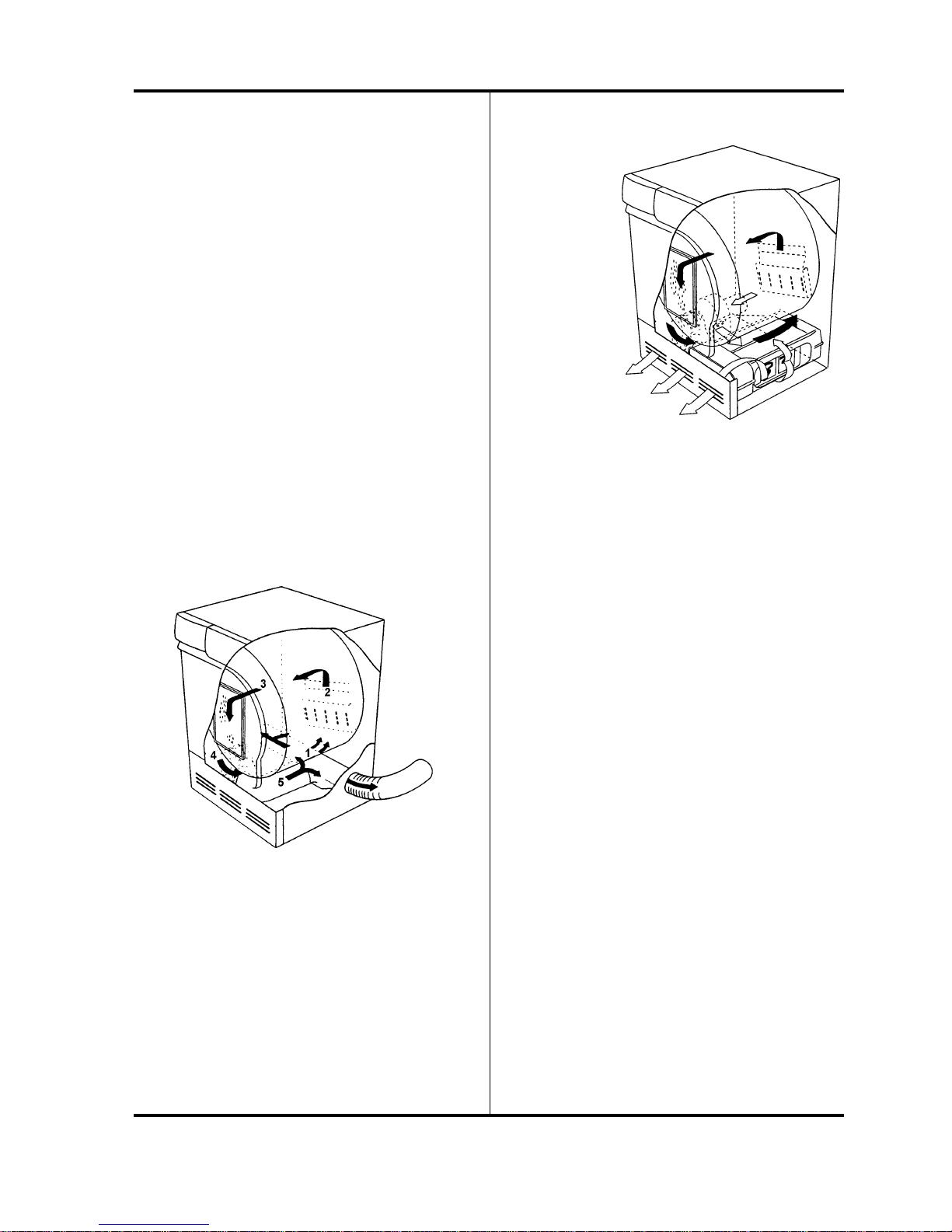
These models are vented dryers; therefore, they
requiredoutsideventingforaproperinstallation.
Room temperature air is heated by the heating
elementanddrawnintothedrum,whereitextracts
thedampness fromtheclothes.Thepaddles inthe
drumpreventtheclothesfromstickingtoeachother.
Air passes through the lint filter in the front door,
throughtheexhaustsystemandouttheexhaustvent.
On Model T700, on the way through the air
extractionsystem,theairpassesoverthethermostats.
Thethermostatsmeasurestheexhausttemperature
as it leaves the dryer. When using the automatic
program,thethermostatsindicatewhentheclothes
aredry.
On Model T760, on the way through the air
extractionsystem,theairpassesahumiditysensor.
The sensor measures the amount of humidity in
theclothes.Ifyouareusinganautomaticprogram,
thesensorindicateswhentheclothesaredry.
THE DRYING PROCESS
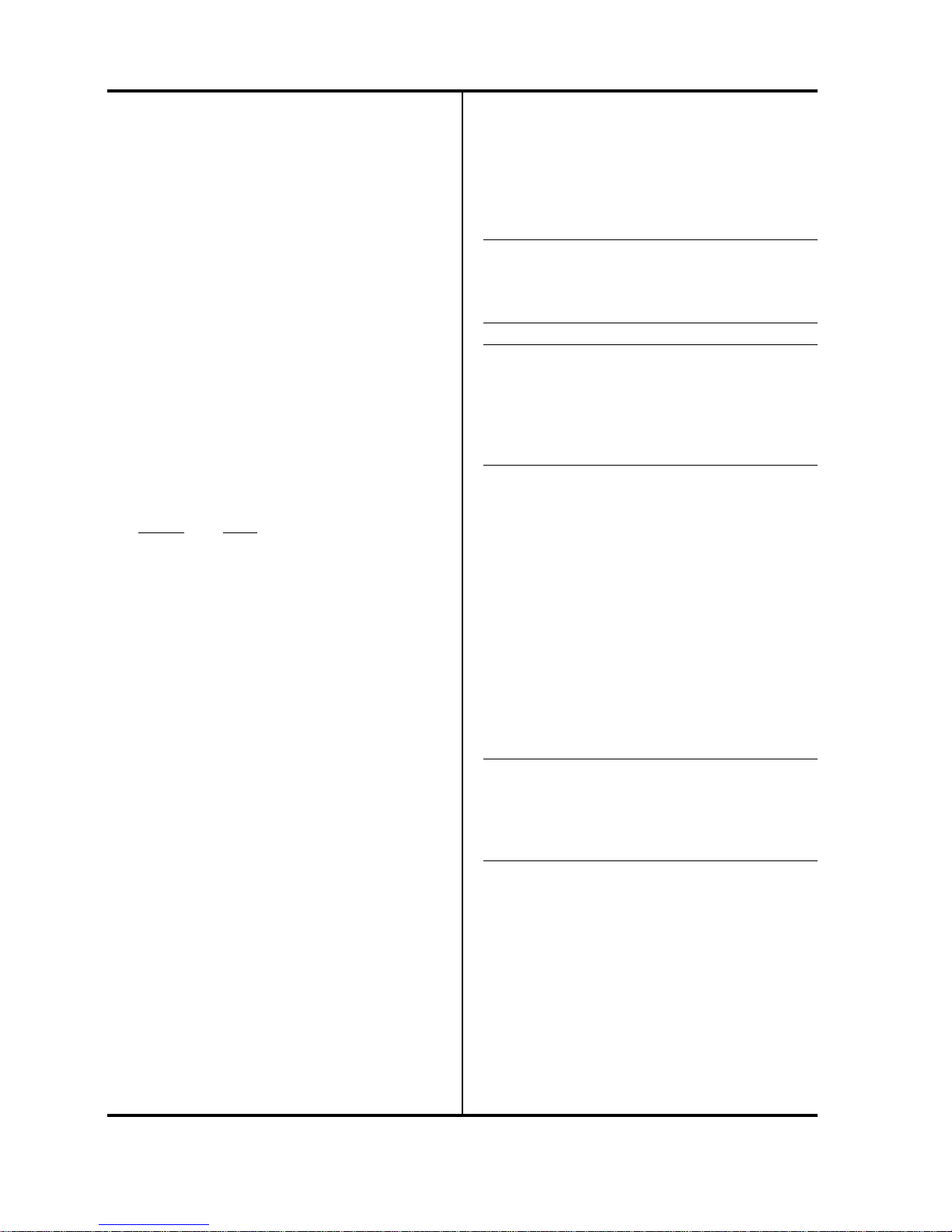
T720 AND T780 – CONDENSING DRYERST720 AND T780 – CONDENSING DRYERS
T720 AND T780 – CONDENSING DRYERS
These models are non-vented, condensing dryers
thatareusedinareaswhereventingisnotpossible.
Condenserdryershavetwocirculationsystems:one
for drying air and one for cooling air. In the
following illustration, the black arrows show the
warm drying air, and the white arrows the cooling
airatroomtemperature.
1. Room temperature air
2. Air that has been heated.
3. Maist air going through the lint filter
4. Air passing the thermostats
5. Air going out the exhaust
Model T720 is a timed dryer only. The user sets
the amount of time for the dryer to run.
Thedrumpaddlespreventtheclothesfromsticking
toeachother.Onthewaythroughtheairextraction
system,theairpassesahumiditysensor.
Model T780hasasensorthatmeasurestheamount
of humidity in the clothes. If you are using an
automatic program, the sensor indicates when the
clothesaredry.
DRYING AIRDRYING AIR
DRYING AIR
Room temperature air is heated by the heating
element and passes through the drum, where it
blowsthroughtheclothesandextractsthedampness
from them.
Theairisfilteredthroughthelintfilterinthefront
door, goes down to the fan and onwards to the
condenserunit.
Onitswaythroughthecondenserthesaturatedair
releasesitswater content.The extractedwater falls
intoaholder,fromwhichitiseitherpumpedupto
awater tankortakenoutviaadrainhose toafloor
drainorsimilar.
COOLING AIRCOOLING AIR
COOLING AIR
Thecondenseriscooledbyairatroomtemperature,
drawninthroughtherearofthemachine.Theairis
blownthroughthecondenserandexhauststhrough
a grill in the bottom hatch. If the machine is built
into a cabinet, the air is drawn through the gap
between the floor and the bottom of the machine.
T700 and T760 Air Circulation
T720 and T780 Air Circulation
The black arrows
show the warm
drying air. The
white arrows
show the cooling
air at room
temperature.

4
INSTALLATION
Read these instructions carefully and completely
before you install the machine. The installation
shouldbecarriedoutbyaqualifiedservicetechnician
who is familiar with all local codes and ordinances
forelectricalandplumbingconnections.
NOTE:
Cosmetic damage must be reported to the dealer
within five days from the date of purchase. After
unpackingthedryer,thoroughlychecktheunitfor
cosmeticdamage.
SPECIFICASPECIFICA
SPECIFICASPECIFICA
SPECIFICATIONSTIONS
TIONSTIONS
TIONS
Height 33-1/2”–34-1/2 (850–876 mm)
Width 23-7/16” (595 mm)
Plus exhaust hose connection
Depth T760/T780: 23-7/16" (595 mm)
T700/T720: 24-7/16” (620 mm)
Depth w/door open All Models: 46-1/16”
Weight T700/T760: 86 lbs (39 kg)
T720/T780: 103 lbs (47 kg)
Drum material Stainless Steel
Outer casing Stove-enamelled hot-dipped
galvanized steel with powder
coat paint or Stainless Steel
on T760 and T780
Power requirement 2800 watts
Electrical connection Stand-alone: single-phase,
208–240 V, 15 Amp
ASKO washer connected to
ASKO dryer: single-phase,
208–240 V, 30 Amp
Internal fuses (2) 15 amp.
Heating element 2500 watts
Speed 52 rpm
Drain(T720/780) 7’ 6-3/4” rubberhose
Venthose Must be UL, CSA, or CUL
(notprovided) approved.
AIR EXHAUST CONNECTION (T700/T760)AIR EXHAUST CONNECTION (T700/T760)
AIR EXHAUST CONNECTION (T700/T760)
The exhaust hose can be connected at the rear or on
eithersideofthedryer.Whenthemachineisdelivered,
the exhaust outlet at the rear is open.The exhaust air
hoseshouldberoutedtheshortestpossiblewayandas
straight as possible from the dryer to the formal vent
section.Thiswillensureproper,moreefficientdrying.
Thedryerisshippedwithastubpipealreadyinstalled
ontherearexhaustoutlet.Theconsumerorinstaller
mustpurchaseaUL-CSA-approvedexhausthose.
The length of the vent for dryers can vary. The
generaluseis22feetof4-inchridgedventhoseina
straight run. Subtract 4 feet for every 90° elbow,
includinganyelbowatthedryer.
WARNINGWARNING
WARNINGWARNING
WARNING
To reduce the risk of fire, vented dryers must be
exhausted outdoors or the equivalent.
Exhaust Hose ConnectionExhaust Hose Connection
Exhaust Hose Connection
To connect the exhaust hose to the rear outlet,
follow the steps below:
1. Pushtheventhoseontothestubpipeandsecure
it with a clamp.
2. Withthehoseattached,insertthestubpipeinto
thehole. It shouldsnapinto place.
3. After you push the dryer into place, check for
kinks in the hose. (Be careful not to use too
muchhose.)
WARNINGWARNING
WARNINGWARNING
WARNING
Never cover the end of the dryer stub or vent
hosewithanythingtocatchlint,except for a UL-
approved vent basket.
Exhaust Outlet
Stub
Clamp
Hose
(not provided)

5
INSTALLATION
CONDENSACONDENSA
CONDENSACONDENSA
CONDENSATION DRAIN CONNECTIONTION DRAIN CONNECTION
TION DRAIN CONNECTIONTION DRAIN CONNECTION
TION DRAIN CONNECTION
(T720/T780)(T720/T780)
(T720/T780)
If possible, you should install the dryer so the
condensedwaterwillcontinuouslyflowintoadrain
or sink.To do this, follow the instructions below:
1. Disconnect the short hose (1) from the blue
nipple. (It’s okay to let the hose hang down.)
2. Connecttherubberhosesuppliedwiththedryer
to the blue nipple (2).
3. Run the hose to a drain or sink, as illustrated.
Try to keep the hose as straight as possible.
NOTE
The drain hose must not be more than 40” (1016
mm) above the floor.
Back of dryer
40”
(1016mm)
maximum
height
CONNECTION TCONNECTION T
CONNECTION TO A VENTILAO A VENTILA
O A VENTILAO A VENTILA
O A VENTILATIONTION
TIONTION
TION
DUCT (T700/T760)DUCT (T700/T760)
DUCT (T700/T760)
1. Connect the exhaust hose to a ventilation
exhaustfittingortoadischargethroughthewall.
2. Secure the hose joint to the outlet stub on the
machine.
3. Run the hose with as few bends and loops as
possibletothepointofdischarge.Ifnecessary,it
canbeextendedtoamaximumof22feet(6600
mm) of 4” (100 mm) diameter ridged hose.
Makeanybendsasgentleaspossible.Amaximum
of four 90° bends may be fitted in the hose. The
morebendsandthelongerthehose,thelessairwill
circulate through the machine, which will impede
dryingperformance.Subtract4feet(1200mm)for
every 90° elbow.
Ifmorethan22 feet ofhoseisneeded, the diameter
mustbeincreasedto6”or8”(152mmor203mm).
Ifthehoseistakentoawalloutlet,aventilationgrill
should be fitted to prevent reverse flow of cold air.
WARNING!WARNING!
WARNING!WARNING!
WARNING!
This appliance should never be exhausted into a
chimney, a wall, a ceiling, or a concealed space of
a building. Only a metal ventilation grill should
be used.
Subtract 4 feet
(1200 mm) for
every 90° elbow.
Make sure nothing is blocking the ventilation grill.
Fit the ventilation grill to the
outside or inside of the wall.
Ventilation grill

6
INSTALLATION
FREESTFREEST
FREESTFREEST
FREESTANDING INSTANDING INST
ANDING INSTANDING INST
ANDING INSTALLAALLA
ALLAALLA
ALLATIONTION
TIONTION
TION
Thedryercanbeplacednexttothewashingmachine.
There should be at least 1/2” (12.5 mm) of space
betweenthewasheranddryer.
It is essential that the machine is level and the
locknutsaretighttoeliminatevibration.
When installing the dryer next to a wall, be sure to
leave at least 1/2” (12.5 mm) of space between the
unit and the wall. This allows for door swing of
dryer. Never push the washer flush against the wall
becauseitmaydamagethemachinecasingorthewall.
All hole measurements are
to the center of the holes.
NOTE
Donotraisethedryerhigherthan34-1/2”.
BUILBUIL
BUILBUIL
BUILTT
TT
T-IN INST-IN INST
-IN INST-IN INST
-IN INSTALLAALLA
ALLAALLA
ALLATION (T700/T760)TION (T700/T760)
TION (T700/T760)TION (T700/T760)
TION (T700/T760)
ModelsT700 andT760 can be installed beneath a
cabinet or worktop with a minimum height of 34”
(864 mm).There must be a gap of about 1/4” (.64
mm)allaroundthemachine,includingbetweenthe
rearedgeofthemachinetoppanelandthebackwall.
Theopening widthmust beat least24” (610 mm).
Spacemustalsobeavailablefortheexhausthoseon
theleft,rightorrearofthemachine.Seethediagram
for hole sizes and positions. Note that the hole
measurementsareto the centerofthe hole.
When installing the
dryer next to a wall, be
sure to leave at least
1/2” of space between
the unit and the wall.

7
INSTALLATION
STST
STST
STACKED INSTACKED INST
ACKED INSTACKED INST
ACKED INSTALLAALLA
ALLAALLA
ALLATIONTION
TIONTION
TION
ASKO dryers can be mounted on top of any
matchingASKOwasher.Mountsaresuppliedwith
themachine.
Toinstallthedryerontopofthewasher,followthe
steps below:
1. Remove the two outside screws (20 torx) from
the back of the washer that holds the top in
position and use them to secure the metal
brackets,asillustrated.
2. To ensure the dryer is correctly positioned on
top of the washer, align the plastic cups with
the front top edge of the washer.
To position the plastic cups, break off the left
tab (A) on the cup to be placed on the right
side of the washer and break off the right tab
(B) on the cup to be placed on the left side of
thewasher.Putthecupinplacebeforeremoving
theprotectivepapertogetageneralareawhere
thecups willbe placed.
4. Once the cups are in place, break off the
remainingplastictabs.
5. Lift the dryer into
position. Raising the
front edge, push the
dryer backwards until
it engages with the
brackets on the back
of the washer.
6. Carefully lower the
front of the dryer,
makingsurethefeetfit
intotheplasticcups.
Tumble dryer
Washer
Stacked InstallationStacked Installation
Stacked Installation
WARNING!WARNING!
WARNING!WARNING!
WARNING!
Never stack a washer on top of a dryer!
Total height 67”.
Adjustable to 69”.
Plastic cups
Washer
back
Metal brackets
Two metal brackets for
securing the dryer to
the washer Two plastic cups to
secure the dryer legs.
3. Remove the protective
paper from the self-
adhesivesurfacebeneath
the cups. Being careful
nottopresstheadhesive
surface against the top
ofthewashingmachine,
use the tabs to position the cups (as illustrated)
thenpressthemfirmly into place.

8
INSTALLATION
Connecting a ThreeConnecting a Three
Connecting a Three-wire P-wire P
-wire P-wire P
-wire Power Cordower Cord
ower Cordower Cord
ower Cord
ELECTRICAL CONNECTIONSELECTRICAL CONNECTIONS
ELECTRICAL CONNECTIONS
The power supply cord must be grounded. If the
machineistobeusedinawetarea,thesupplymust
beprotectedbyaresidualcurrentdevice.
Connection to a permanently wired supply point
mustbe made onlybya qualifiedelectrician.
Assupplied: Single-phase, 208–240V, 60 Hz,
2800 Watt total rating
2500Wattheaterrating
NOTE:NOTE:
NOTE:NOTE:
NOTE:
InCanada,thedryerisdeliveredready-fittedwitha
four-prongplug intendedforconnectiontoasingle-
phasesupply.
WARNING:
The receptacle on the rear of the machine is
designed to accommodate ASKO washers ONLY
(rated 208–240 V.) To use this receptacle, you
must use the ready-fitted plug supplied with the
washing machine or an equivalent. The supply
connection must be 208–240 V, 20 A.
ASKOwashersrated208–240Vhavetwointernal
fuses of 15 A each.
Remove cover to
access terminal box.
(Requires a 20-Torx
screwdriver.)
WARNING!WARNING!
WARNING!WARNING!
WARNING!
Before starting this procedure, be sure the power
is turned off at the breaker/fuse box.
Power Supply Cord
You will need a three-wire power supply cord with
three No. 10 copper wires and a matching three-
wirereceptacleofNEMAType10-30R,asillustrated
below:
1. Turn the power off at the breaker/fuse box.
2. Remove terminal block cover (20 torx).
3. Assemble 3/4”
UL-listed strain
relief into the
hole below the
terminal block
opening.
4. Loosen or
remove center
terminal block
screw.
5. Connect neutral
wire (white ) of
power supply
cord to the
center, silver-
colored terminal
screw.Tightenscrew.
6. Connectthe other wirestoouter screws.
7. Tightenthestrainreliefscrews.
8. Replace terminal box cover on back of dryer.
9. Plugdryerintowallreceptacle.
10.Turn power on at breaker/fuse box.
11.Turn on the main power switch on the dryer.
(The power indicator light should come on.)

9
INSTALLATION
Connecting a FourConnecting a Four
Connecting a Four-wire P-wire P
-wire P-wire P
-wire Power Cordower Cord
ower Cordower Cord
ower Cord
WARNING!WARNING!
WARNING!WARNING!
WARNING!
Before starting this procedure, be sure the power
is turned off at the breaker/fuse box.
Power Supply Cord
You will need a four-wire power supply cord with
fourNo.10copperwiresandamatchingfour-wire
receptacle of NEMA Type 14-30R, as illustrated
below. The fourth wire must be identified with a
green cover and the neutral conductor by a white
cover.
1. Turn the power off at the breaker/fuse box.
2. Remove terminal block cover.
3. Assemble 3/4” UL-listed strain relief into the
hole below the terminal block opening.
4. Removecenter terminalblock screw.
5. Remove ground
wire (green with
yellow stripes)
from external
groundconnector
screw.Fastenunder
center, silver-
colored terminal
block screw.
6. Connect ground
wire (green) of
cord to external
groundconductor
screw.
7. Connect neutral wire (white) of cord under
centerscrewof terminalblock.
8. Connectthe other wirestoouter screws.
9. Tightenthestrainreliefscrews.
10.Replaceterminalbox coveron back of dryer.
11.Plugdryerintowallreceptacle.
12.Turn power on at breaker/fuse box.
13.Turn on the main power switch on the dryer.
(The power indicator light should come on.)

10
INSTALLATION
REVERSING THE DOOR HINGESREVERSING THE DOOR HINGES
REVERSING THE DOOR HINGES
ThedoorhingesonASKOdryersarereversible.The
dryers are shipped left-hinged. To reverse them,
follow the steps below:
WARNING!WARNING!
WARNING!WARNING!
WARNING!
Switchoff themainpower supplybefore youstart
this procedure.
3. Pull the door out and to the left
as you turn the hinge counter
clockwise.
4. Remove the top hinge pin
thenturnthehingeupside
down and put the hinge
pin into the top hole.
1. Remove the lower cover
by first removing the
two screws (A) at the
bottom of the machine.
Next, grasp the sides and pull it forward and
down.
2. Remove the
three screws
holding the
hinge.
5. Repeat steps 1–4 for the bottom hinge.
8. Remove the cover
plate by pushing it
downthenliftingit
out from the top.
7. Remove the door
latch by pushing it
up then lifting it
out from the
bottom.
9. Reverse steps 6 and 7 to place the door latch
andcoverplateinto their newpositions.
10.Tighten the screws on the sides of the doors to
holdthelatchandcoverplateinplace.
12.Remove the screw in the top
rightcornerofthelowercover,
asindicatedintheillustration.
(Ifyouhaveacondenserdryer,
you will need to open the
condensercontainerdoor.)
13.Now you are ready to mount the door on the
right side. Holding the door at an angle (as
illustrated),fit the hinge pin into the tophole.
11.Using a flathead screwdriver,
remove the plastic plugs in the
upperandloweredgeofthedoor
and place them in the empty
holesonthe oppositeside.
14.Tighten the screws in the
orderillustratedatright(a,b,
c).
15.Replace the screw you
removed in step 12 (d).
16.Replace the lower cover (see Step 1 on this
page).
6. Loosenthetwoscrewsonbothsidesofthedoor
soyoucanremovethemagneticdoorlatchand
thecoverplate.

11
DRYERFEATURES
FRONT VIEWFRONT VIEW
FRONT VIEW REAR VIEWREAR VIEW
REAR VIEWREAR VIEW
REAR VIEW
Condensed water
container
(T720 & T780)
Control
panel
Bottom
cover
Lint filter
Lint filter
cover
Reversible
door
Front
panel
Side
panel
Top
cover
Condensed
water drain
hose (T720
and T780)
Reset
button
NOTE: Canadian dryers
are equipped with an
electrical cord.
Terminal
box
Receptacle for
ASKO washer

12
OVERHEAOVERHEA
OVERHEAOVERHEA
OVERHEAT PROT PRO
T PROT PRO
T PROTECTIONTECTION
TECTIONTECTION
TECTION
ASKO dryers are designed with an overheat
protection switch that automatically turns off the
machineifthe temperatureis toohigh.Thiscould
happen if the lint filter or exhaust hose becomes
clogged with dust.
Should the machine turn itself off because of
overheating,firstmakesurethefollowingpartsare
cleanandfree of lintanddirt:
• lintfilter and filtercover
• exhausthose,exhaustventandhose
• fanhousingandfan
If none of these are the problem, check the
following:
• Check both 15 Amp fuses on the back of the
dryer
• Be sure the switch actuator is making contact
with the Start switch.
• OnmodelsT760andT780makesureaprogram
(P1–P4)hasbeenchosen.
• Check for a control unit fault
• Checkfora heating elementfault
NOTE:
If the dryer overheats frequently, it may not be
vented properly or the room in which it is located
maynothavesufficientaircirculation.
Press the reset
button to start the
machine. You should
hear a click when
the reset button is
depressed.
OVERHEAT PROTECTION
If the overheat protection switch is activated, you
have to reset it before the machine will run.To do
this,presstheresetbutton(rubberdisk)ontheback
ofthemachine,asillustratedtotheright.Youshould
heara click whenit engages.Themachine will not
start until ithas cooledsufficiently.

13
FAULT TRACING
The machine won’t start.The machine won’t start.
The machine won’t start.
1. Makesurethepoweristurnedon.(Theindicator
light should glow red.)
2. Checkthatyousettheprogramortimecorrectly.
3. Make sure the door is closed securely.
4. On Models T720/T780, make sure the
condensertankisempty.
5. Check that the electric plug is securely in the
socket.
6. Checkthehousebreaker/fuses.
7. If all of the above options are eliminated, the
overheatprotectionhasprobablybeenactivated.
(See page 12.)
The machine starts but it stops when IThe machine starts but it stops when I
The machine starts but it stops when I
release the Start button.release the Start button.
release the Start button.
1. The overheat protection has probably tripped.
Clean the lint filter and let the machine cool
downbeforetrying again. (Seepage12.)
The machine takThe machine tak
The machine takes too long to dryes too long to dry
es too long to dryes too long to dry
es too long to dry.....
1. Makesurethedryerisinstalledaccordingtothe
instructionsonpages4–10.
2. Checkthatthe lint filterisclean.
3. If dryer sheets are being used (not
recommended), the lint filter may need to be
washed with warm water and a soft brush to
cleananyblockedholes.
4. The dryer may be overloaded, not allowing
sufficient room for the warm air to circulate
properly or the clothes to tumble freely.
5. Thelaundryshouldonlybedampwhenitcomes
outof thewasher.Ifit seemstoo wet, it should
be spun in the washer at a faster or longer spin
cycle.
6. Make sure the outside vent exhaust is not
blocked.
7. On models T720/T780, make sure the
condenser is not blocked with dust or lint.
The clothes are coming out wrinkled.The clothes are coming out wrinkled.
The clothes are coming out wrinkled.
1. The clothes should be removed as soon as the
dryer signals the end of the cycle. If it isn’t
possible to remove the clothes right away, use
theAnti-creaseoption.
2. Heavyfabricsand lightfabrics should bedried
separately.
3. Dryonlypermanentpressitemstogether.
4. Dryinsmallerloads.
5. Useslowerspinspeeds.
6. Usefabric softenerintherinseprogram.
7. Tryusingalowerwash temperature,especially
forpermanentpressanddelicateitems.
8. Make sure the customer is using the correct
temperatureforthetype(s)offabricbeingdried.
The motor is running but the drum isn’tThe motor is running but the drum isn’t
The motor is running but the drum isn’t
turning.turning.
turning.turning.
turning.
1. The drive belt could be broken.
2. Thedrivebeltmaybedislodgedfromthemotor
pulley.
3. The drive belt may be off the idler pulley.
4. Be sure nothing is preventing the drum from
turning.
The machine makes a funny noise.The machine makes a funny noise.
The machine makes a funny noise.
1. Aslightrumblingmaybeheard when you first
turnon thedryer.This is normaland itshould
only last a few seconds.
2. Make sure the customer wasn’t drying tennis
shoes or something heavy when the noise was
heard.
3. Snaps, zippers and buttons can hit the side of
thedrumandcausesomenoise.
ERROR MESSAGESERROR MESSAGES
ERROR MESSAGES
On Models T760 and T780, the LED window
displaysanerrormessageifafaultoccursduringthe
timetheprogramisrunning.Theseerrormessages
arelistedon page 18.

14
The washing will not dryThe washing will not dry
The washing will not dry.....
The machine only runs for 20 minutes.The machine only runs for 20 minutes.
The machine only runs for 20 minutes.
1. Checkthe main power fuse.
2. Make sure the dryer wasn’t overheated due to
lint blocking the filter, condenser unit or fan
housing.
3. Model T780: Overfilling. (The display shows
"Faultindication,filling.")
4. Possibly,themachinedidnotreachthemeasured
valueof1.8mVwithin15minutes. Thiscould
be due to:
a. Incorrectconnectiontosinglephase–too
lowheatingelementpower(720or600W)
b. Incorrectconnectionofelementtocontrol
unit
c. Incorrect connection in element terminal
block
d. Humiditysensornotlocatedinfanhousing
e. Faultyhumiditysensor
f. Heatingelementopencircuit
5. Check the drive belt for the following:
a. Improperly located on the motor pulley.
b. Improperlylocated onidler pulley.
c. Twisted.
Overheat protection tripped even thoughOverheat protection tripped even though
Overheat protection tripped even though
lint filter and condenser unit have beenlint filter and condenser unit have been
lint filter and condenser unit have been
cleaned.cleaned.
cleaned.cleaned.
cleaned.
1. Checkfor lint inthe internalfanwheel.
2. Cleantheairductsandbehindtheelement.
3. Check for a fault in the control unit
Overfilling fault indication, even thoughOverfilling fault indication, even though
Overfilling fault indication, even though
tank is emptytank is empty
tank is empty.....
Condenserwaterpumpcouldbeblockedorburned
out. If the pump is burned out, an associated fault
will be burned wiring in the control unit. Always
checkfirstifthecondenserwaterpumphasburned
outbefore installinga new control unit.
The machine shows the maximum programThe machine shows the maximum program
The machine shows the maximum program
time fault indication.time fault indication.
time fault indication.
This indicates that the machine has been running
for the maximum time that the control unit is
allowed (> 3 hours) .
Several things could cause this. (It could be one of
theseitemsor a combination.)
1. Checkthe main power fuse.
2. Make sure the dryer wasn’t overheated due to
lint blocking the filter, condenser unit or fan
housing.
3. Makesurethedryerisn’tincorrectconnectedto
asinglephase,15A.
4. Check that the external air isn’t restricted or
blocked,resultinginpoorcondensation.
5. A high ambient temperature + low heating
elementpower+lowdryingtemperaturecould
resultinpoorcondensation.
6. A low ambient temperature + low heating
elementpower+lowdryingtemperaturemakes
it difficult to get the dampness out of the
clothes.
7. It’s possible the washing was spun dry at low
speed (i.e., less than 800 rpm), which would
make it difficult to dry the washing.
8. Thewashingpossibly wastakenout before the
program was complete and the machine was
loadedwithanewbatchofwashing.Inthiscase,
thecontrolunitprobablywouldnot have time
to reset itself and the remaining program time
wasaddedto thenextdrying cycle.
9. Check the humidity sensor, its wiring and
connections.
COMMONPROBLEMS

15
MOTOR (2/118/JU) 50 HZMOTOR (2/118/JU) 50 HZ
MOTOR (2/118/JU) 50 HZ
Part number: 80 618 24
Mainwinding: 23,8 Ω
Auxiliary-winding: 28,1 Ω
Voltage: 220/240 V
Current: 1,1 A, 270 W, 2850 rpm
The two-pole motor is connected directly to the
fanforinternalairandviaageartodrivethedrum.
On machines with condensers (T720/780) it also
drivesthe fan for external air.
CAPCAP
CAPCAP
CAPACITACIT
ACITACIT
ACITOROR
OROR
OR
Part number: 80 542 68
The capacitor is located on the motor and has a
value of 8µF.
CONDENSED WCONDENSED W
CONDENSED WAA
AA
ATER PUMP (T720/T780)TER PUMP (T720/T780)
TER PUMP (T720/T780)TER PUMP (T720/T780)
TER PUMP (T720/T780)
Hanning 25WHanning 25W
Hanning 25W
Part number: 80 638 09
Resistance: 111 Ω
The condensation water pump pumps the water
fromthecondenserhousingattherearofthemachine
to the water tank.
RADIO INTERFERENCE FILRADIO INTERFERENCE FIL
RADIO INTERFERENCE FILTERTER
TERTER
TER
Part number: 80 585 58
Leakagecurrent: 230 V/ 50 Hz 0.315 mA
Thefiltereliminatesradiointerferencegeneratedby
themachine.
INDICAINDICA
INDICAINDICA
INDICATOR LAMPTOR LAMP
TOR LAMPTOR LAMP
TOR LAMP
Part number: 80 070 73
Current: 1.68 mA, 230 V, 50 Hz
The lamp indicates that the main power switch is
set to on.
THERMISTOR (T760/T780)THERMISTOR (T760/T780)
THERMISTOR (T760/T780)
Part number: 80 619 00
Resistance: 40-60 kΩ at 20°-30°C
Thethermistorcontrolstemperatureregulation.Ifthe
thermistor becomes short-circuited or disconnected
fromthecontrolunit, the program stops.
CONTCONT
CONTCONT
CONTACTACT
ACTACT
ACTOROR
OROR
OR
Part number: 80 091 48
Resistance: 2 kΩ
The contactor opens in case of overheating, when
the door is opened and at the end of the program.
THERMOSTTHERMOST
THERMOSTTHERMOST
THERMOSTAA
AA
ATSTS
TSTS
TS
T700T700
T700T700
T700
Part number:
Low 80 619 46 (111° F/44°C)
Normal 80 014 45 (127° F/53°C)
Overheat 80 088 07 (239° F/115° C)
The thermostats are located in the fan housing. It
controls the temperatures for the automatic
programsandthetimeprogramupto60minutes.
The 239° F thermostat automatically disconnects
oneoftheheatingloopsifthetemperaturerisestoo
high.Thisthermostatislocatednexttotheheating
elementat the rearofthe dryer.
T720T720
T720T720
T720
Part number:
Low 80 144 44 (118° F/47° C)
Normal 80 560 29 (158° F/70° C)
This thermostat is located in the fan housing. It
controlsthetemperaturefortheautomaticprograms
and the time program up to 60 min.
OVERHEAOVERHEA
OVERHEAOVERHEA
OVERHEAT PROT PRO
T PROT PRO
T PROTECTION THERMOSTTECTION THERMOST
TECTION THERMOSTTECTION THERMOST
TECTION THERMOSTAA
AA
ATT
TT
T
Part number: 80 084 87 (302° F/150°C
manual)
This thermostat stops the program if the
temperature rises too high. The unit has to be
manually reset. It is located next to the heating
elementat the rearofthe dryer.
HUMIDITY SENSOR (T760/T780)HUMIDITY SENSOR (T760/T780)
HUMIDITY SENSOR (T760/T780)
Part number: 80 618 55
The humidity sensor is used to control the drying
process.Duringoperationthesensoroutputsignal
isbetween1and16mVDC.Anyothervaluecauses
the program to stop.
OVERFILL PROTECTION (T720/780)OVERFILL PROTECTION (T720/780)
OVERFILL PROTECTION (T720/780)
Part number: 80 526 43
If both of the dryer containers are overfilled, the
program is stopped by a switch in the lower
container.TheLEDwindowindicatesoverfilling.
COMPONENTS AND MEASUREMENT VALUES

16
39
40
41
42
43
53
54
55
56
57
1+2 11+2 11+2 1OFF 111OFF
OFF1+2
1+2 11+2 11+2 1OFF 212OFF
OFF1+2 Low Temperature
Normal Temperature
1 = High Power Heater
2 = Low Power Heater
Temperature ˚C
ELECTRICAL CONNECTIONSELECTRICAL CONNECTIONS
ELECTRICAL CONNECTIONS
(Seepages8 and9.)
DOOR SWITCHDOOR SWITCH
DOOR SWITCH
Part number: 50 531 07
Thedooroperatesadoorswitch.Whenthedooris
opened, the program stops. If the door is opened
andclosed during the program, the machine must
berestarted withthe Start button.
BUZZER (T700/T720)BUZZER (T700/T720)
BUZZER (T700/T720)
Part number: 80 618 83
Thebuzzersoundstoindicatethattheprogramhas
finished.
COMPONENTS AND MEASUREMENT VALUES
PROGRAM CONTROL UNIT (T760/T780)PROGRAM CONTROL UNIT (T760/T780)
PROGRAM CONTROL UNIT (T760/T780)
Thecontrolunitcontainsmicroprocessorstocontrol
theprogram,motor, heating elementetc.
LED WINDOWLED WINDOW
LED WINDOW (T760/T780)(T760/T780)
(T760/T780)(T760/T780)
(T760/T780)
The LED window displays selected programs and
optionsandprogram information.(Seepage xx.)
PROGRAMMER (T700/T720)PROGRAMMER (T700/T720)
PROGRAMMER (T700/T720)
Theprogrammerhasmechanicalsettingpointsand
a motor with four-minute steps.
HEAHEA
HEAHEA
HEATING SEQUENCE FOR MODELS T700 AND T760TING SEQUENCE FOR MODELS T700 AND T760
TING SEQUENCE FOR MODELS T700 AND T760TING SEQUENCE FOR MODELS T700 AND T760
TING SEQUENCE FOR MODELS T700 AND T760

17
COMPONENTS AND MEASUREMENT VALUES
46
47
48
49
50
69
(64)
70
(65)
71
(66)
72
(67)
73
(68)
1+2 11+2 11+2 1OFF 111OFF
OFF1+2
1+2 11+2 11+2 1OFF 212OFF
OFF1+2 Low Temperature
Normal Temperature
1 = High Power Heater
2 = Low Power Heater
Temperature ˚C
HEAHEA
HEAHEA
HEATING ELEMENTTING ELEMENT
TING ELEMENTTING ELEMENT
TING ELEMENT
T700/T760 – 2620 WT700/T760 – 2620 W
T700/T760 – 2620 W
Part number: 80 618 33
Resistance: 66.7/25.7Ω
The element has a maximum power rating of
2620W but consists of two loops of 1900W and
720W, which permits rewiring from 2620W to
1900W.
HEAHEA
HEAHEA
HEATING SEQUENCE FOR MODELS T720 AND T780TING SEQUENCE FOR MODELS T720 AND T780
TING SEQUENCE FOR MODELS T720 AND T780TING SEQUENCE FOR MODELS T720 AND T780
TING SEQUENCE FOR MODELS T720 AND T780
T720/T780 – 2500 WT720/T780 – 2500 W
T720/T780 – 2500 W
Part number: 80 637 71
Resistance: 79,7/25Ω
The element has a maximum power rating of
2500W but consists of two loops of 1900 W and
600 W, which permit rewiring from 2500W to
1900W.

18
TEST PROGRAMTEST PROGRAM
TEST PROGRAM
Themachinemustbeinitsstartingstate(obtained
bypressing the mainpower button).
Short-circuit the outputs ST4-1 and ST4-2.
Startthe test program.
T780:Startthe condensationwater
pump.
or wait for 60 seconds and the test
programwillcontinue.
Theprogram heats, increasing the temperature by
57° F (14° C) in a maximum of 10 minutes, then
allows it to cool for 5 minutes (testing that the
heatingelementisworking).
Thevaluedetectedbythehumiditysensorcanvary
accordingtotheenvironmentandonwhetherthere
iswetclothing inthe dryer.
ERROR MESSAGES – T760/T780ERROR MESSAGES – T760/T780
ERROR MESSAGES – T760/T780
ErrormessageswilldisplayintheLEDwindowifa
faultoccurswhileaprogramisinprogress.Thetable
belowdefineseachpossibleerrormessage.Oncethe
problemisresolvedyoumayhavetoturnthepower
offthen on to clear the error message.
Message: Three hoursMessage: Three hours
Message: Three hours
The machine has run the maximum drying time
(threehours).
Possiblesolutions:
• Makesurebothfusesareintact.
• Cleanthelintfilter.
• Makesureexhaust hose isclear(T760).
• Makesurethecondenser(T780)isclearoflint
anddust.
• Clearmessagebyturningthepoweroffthenon.
TEST PROGRAM AND ERROR MESSAGES
Message: Overflow (T780)Message: Overflow (T780)
Message: Overflow (T780)
Thecondensedwatercontainerisfull.Thiscontainer
is located at the top left corner of the dryer.
Possiblesolutions:
• Make sure the condensed water container is
empty.Ifdraining into adrainpipe, make sure
theblackrubberhoseisnotkinkedorblocked.
Thedrainshouldnot be higherthan40inches
(1016 mm) from the floor.
• Make sure the condensation pump is not
blocked.
Message: SensorMessage: Sensor
Message: Sensor
This can appear if there are dry clothes in the drum
when the unit is started or if the humidity sensor is
not installed properly in the fan housing or control
unit.Inthiscase,themachinewillstopafter20minutes.
It could also be caused by a fault in the humidity
sensor.Ifthemessagedoesnotdisappearwhenyou
openthe door,checkthe humiditysensor.
Message: ThermistorMessage: Thermistor
Message: Thermistor
The thermistor may have become disconnected or
haveaninternalfault.Aserviceablethermistorhasa
resistanceofbetween60and40kWat68°F–86°F
(20° C–30° C).
Possible causes and solutions:
• The thermistor is not properly installed in the
fan housing. In this case, the heating element
will remain switched in for as long as the
thermistor cannot detect the selected air
temperature.Thiscanleadtoanexcessivelyhigh
airtemperatureinthedrum.
• The filter could be blocked. In this case, the
overheat protection device is tripped and the
machine will stop. Once the unit is cool, press
the reset button on the rear of the machine to
startthemachine.
• Theincoming phase is missing.
– Error L1 – the machine will stop after 20
minutes.Lowheatingelementpower(720
or 600 W).
– Error L2 – the machine will not start.
Indicatorlampnot lit.
– Error L3 – the machine operates but the
running time is too long (low heating
elementpower(1900W)).
• The fan motor stops after a few seconds.
Overheatprotectiontrips,heatingelementand
controldamaged.
Start
P1
P2
Amplified voltage value
from humidity sensor
Temperature measured
by thermistor

19
CONSUMPTION VALUES
T700/T720T700/T720
T700/T720T700/T720
T700/T720
Before tumble drying, cotton garments should be
spun at 800 to 1600 rpm (long spin drying) in an
ASKO washer. Other garments (non-iron and
acrylic) should be spun at 800 rpm (short spin
drying)inanASKOwasher.
Thefollowingconditionsapplyfortheconsumption
valuesstatedbelow:
Incomingairtemperature: 68° F (20° C)
Incomingairhumidity: 65%
Dryingtemperature: Normal ( )
Low ( )
Heatingelementpower: T700 2620W
T720 2500W
T700 CONSUMPTION VALUEST700 CONSUMPTION VALUES
T700 CONSUMPTION VALUES
*Approximate number of pounds for each load size: Full = 11 pounds; Half = 5.5 pounds
** kWh values are based on 800 –1600 rpm spins.
ENERGY
LOAD CONSUMPTION
PROGRAM FABRIC TEMP SIZE* (approx. kWh) **
1. Extra dry Cotton,linen Normal Full 3.8 –3.3
2. Normal Dry Cotton,linen Normal Full 3.4 –2.6
Permanent press, cotton/polyester Low Half 1.3 –
Acrylics, rayon, acetates Low Half 1.7
T720 CONSUMPTION VALUEST720 CONSUMPTION VALUES
T720 CONSUMPTION VALUES
*Approximate number of pounds for each load size: Full = 11 pounds; Half = 5.5 pounds
** kWh values are based on 800 –1600 rpm spins.
ENERGY
LOAD CONSUMPTION
FABRIC SIZE * ( approx. kWh) **
Cotton,linen Full 3.1 –2.4
Permanent press, cotton/polyester Half 1.2 –
Acrylics, rayon, acetates Full 1.7 –

20
T760T760
T760T760
T760
Before tumble drying, cotton garments should be
spun at 800 to 1600 rpm (long spin drying) in an
ASKO washer. Other garments (non-iron and
acrylic) should be spun at 800 rpm (short spin
drying)inanASKOwasher.
CONSUMPTION VALUES
T760 CONSUMPTION VALUEST760 CONSUMPTION VALUES
T760 CONSUMPTION VALUES
*Approximate number of pounds for each load size: Full = 11 pounds; Half = 5.5 pounds
** kWh values are based on 800 –1600 rpm spins.
Thefollowingconditionsapplyfortheconsumption
valuesstatedbelow:
Incomingairtemperature: 68° F (20° C)
Incomingairhumidity: 65%
Dryingtemperature: Normal ( )
Low ( )
Heatingelementpower: 2620 W
T780T780
T780T780
T780
Before tumble drying, cotton garments should be
spun at 800 to 1600 rpm (long spin drying) in an
ASKO washer . Other garments (non-iron and
acrylic) should be spun at 800 rpm (short spin
drying)inanASKOwasher.
Thefollowingconditionsapplyfortheconsumption
valuesstatedbelow:
Incomingairtemperature: 68° F (20° C)
Incomingairhumidity: 65%
Dryingtemperature: Normal ( )
Low ( )
Heatingelementpower: 2500 W
T780 CONSUMPTION VALUEST780 CONSUMPTION VALUES
T780 CONSUMPTION VALUES
*Approximate number of pounds for each load size: Full = 11 pounds; Half = 5.5 pounds
** kWh values are based on 800 –1600 rpm spins.
ENERGY
LOAD CONSUMPTION
PROGRAM FABRIC TEMP SIZE * (kWh) **
P1 Extra dry Cotton,linen Normal Full 4.1 –3.4
P2 Dry Cotton,linen Normal Full 3.9 –3.1
Permanent press, cotton/polyester Low Half 1.7 –
P3 Normal dry Cotton,linen Normal Full 3.4 –2.6
Permanent press, cotton/polyester Low Half 1.5 –
Acrylics, rayon, acetates Low Half 1.7 –
P4 Iron dry Cotton,linen Normal Full 2.4 –2.0
ENERGY
LOAD CONSUMPTION
PROGRAM FABRIC TEMP SIZE * (kWh) **
P1 Extra dry Cotton,linen Normal Full 3.8 –3.1
P2 Dry Cotton,linen Normal Full 3.5 –2.8
Permanent press, cotton/polyester Low Half 1.4 –
P3 Normal dry Cotton,linen Normal Full 3.4 –2.6
Permanent press, cotton/polyester Low Half 1.5 –
Acrylics, rayon, acetates Low Half 1.7 –
P4 Iron dry Cotton,linen Normal Full 2.4 –2.0
Other manuals for T700 Series
6
This manual suits for next models
3
Table of contents
Other Asko Dryer manuals