BPC130 / BDIST / MDIST – Product Manual
U-0456-0145.doc – Issue: 04 complete, approved
Page 3 of 40
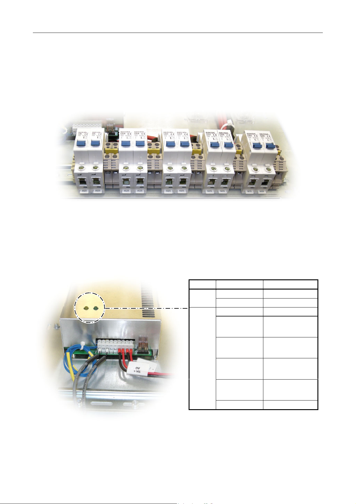
Contents
1Overview .....................................................................................................................................................5
2Operation ....................................................................................................................................................7
2.1 Controls.......................................................................................................................................7
2.2 Indicators.....................................................................................................................................7
3Installation..................................................................................................................................................8
3.1 Equipment and Tool Requirements ............................................................................................8
3.2 Cabling Requirements.................................................................................................................8
3.3 Main Components........................................................................................................................9
3.4 Recommended Installation Procedure .......................................................................................9
3.4.1 Battery Backup System Installation – Rack with 800 mm Depth ......................................10
3.4.1.1 Installing the Battery Tray and Batteries................................................................10
3.4.1.2 Installing the Charger Tray and Charger ................................................................12
3.4.1.3 Connecting the Power Distribution (BDIST)............................................................14
3.4.1.4 Connecting the Batteries.........................................................................................15
3.4.1.5 Fitting the Front Panel ............................................................................................15
3.4.1.6 Powering the system up..........................................................................................16
3.4.1.7 Commissioning the Battery Backup System at the Router.....................................16
3.4.2 Battery Backup System Installation – Rack with 600 mm Depth ......................................17
3.4.2.1 Installing the Battery Tray and Batteries................................................................17
3.4.2.2 Installing the Charger Tray and Charger ................................................................18
3.4.2.3 Connecting the Power Distribution (BDIST)............................................................18
3.4.2.4 Connecting the Batteries.........................................................................................19
3.4.2.5 Fitting the Front Panel ............................................................................................20
3.4.2.6 Powering the system up..........................................................................................20
3.4.2.7 Commissioning the Battery Backup System at the Router.....................................20
3.4.3 MDIST Installation .............................................................................................................20
4Connection Diagram .................................................................................................................................21
5Commissioning .........................................................................................................................................22
5.1 Obtaining the Router’s Contact .................................................................................................22
5.2 Configuring the Router Contact for Fault Reporting ................................................................22
5.3 Configuring the Fault Text ........................................................................................................24
5.4 Configuring the Fault Type........................................................................................................24
6Fault Finding.............................................................................................................................................25
7Maintenance .............................................................................................................................................27
7.1 Visual Inspection .......................................................................................................................27
7.2 Resistance Measurement..........................................................................................................27
7.3 Battery Replacement ................................................................................................................28
7.3.1 800 mm Deep Rack ............................................................................................................28
7.3.2 600 mm Deep Rack ............................................................................................................29
8Product Specification................................................................................................................................30
9Mechanical Dimensions............................................................................................................................32
10 Safety and Precautions.............................................................................................................................35
10.1 Handling ....................................................................................................................................35
10.2 Installation ................................................................................................................................35
10.3 Weight Safety.............................................................................................................................35
10.4 Environmental...........................................................................................................................35
10.5 Electrical Safety ........................................................................................................................35
10.6 Fire / Burn Safety ......................................................................................................................36
10.7 Battery Disposal ........................................................................................................................36