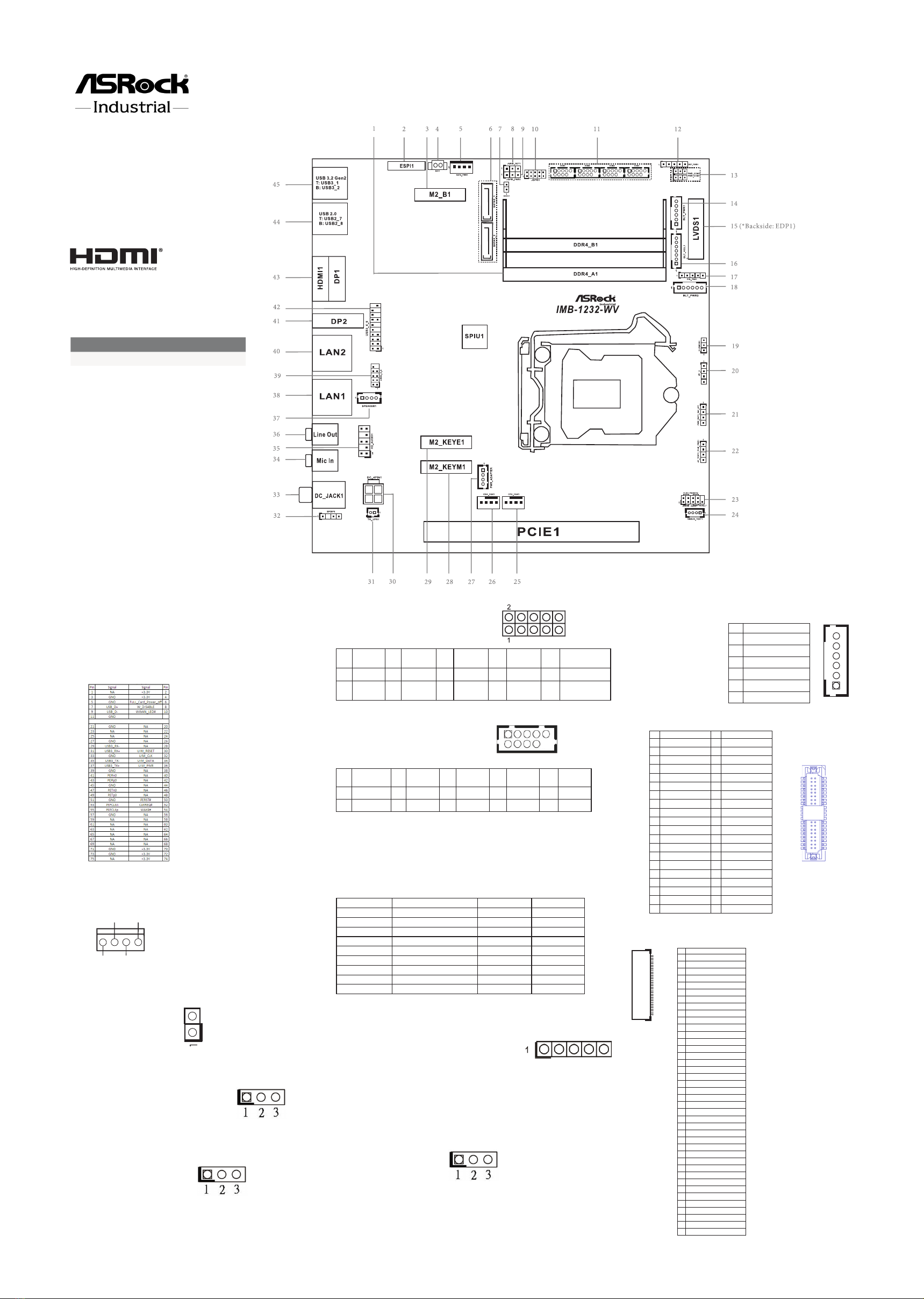
ASRock Industrial IMB-1232-WV Service manual
Other ASRock Industrial Computer Hardware manuals

ASRock Industrial
ASRock Industrial IMB-1005 User manual

ASRock Industrial
ASRock Industrial NUC BOX-J6412 User manual

ASRock Industrial
ASRock Industrial IMB-1714 User manual

ASRock Industrial
ASRock Industrial IMB-1314 Service manual

ASRock Industrial
ASRock Industrial IMB-1241 Service manual

ASRock Industrial
ASRock Industrial IMB-X1314 Service manual

ASRock Industrial
ASRock Industrial NUC-1335UE/D4 User manual

ASRock Industrial
ASRock Industrial iBOX 1300/D4 Series User manual

ASRock Industrial
ASRock Industrial NUC-N97 User manual

ASRock Industrial
ASRock Industrial IMB-1235 Service manual

ASRock Industrial
ASRock Industrial SBC-250J Service manual

ASRock Industrial
ASRock Industrial NUC BOX-1260P User manual

ASRock Industrial
ASRock Industrial IMB-1003 Service manual

ASRock Industrial
ASRock Industrial 4X4-7735U/D5 User manual

ASRock Industrial
ASRock Industrial iBOX ADL-N Series User manual

ASRock Industrial
ASRock Industrial SBC-261J User manual

ASRock Industrial
ASRock Industrial iEP-9010E User manual

ASRock Industrial
ASRock Industrial SOM-P104 Service manual

ASRock Industrial
ASRock Industrial 4X4 BOX-7840U User manual

ASRock Industrial
ASRock Industrial SBC-373-WT Service manual


Popular Computer Hardware manuals by other brands

Toshiba
Toshiba TOSVERT VF-MB1/S15 IPE002Z Function manual

Shenzhen
Shenzhen MEITRACK MVT380 user guide

TRENDnet
TRENDnet TEW-601PC - SUPER G MIMO WRLS PC CARD user guide

StarTech.com
StarTech.com CF2IDE18 instruction manual

Texas Instruments
Texas Instruments LMH0318 Programmer's guide

Gateway
Gateway 8510946 user guide


Sierra Wireless
Sierra Wireless Sierra Wireless AirCard 890 quick start guide

Leadtek
Leadtek Killer Xeno Pro Quick installation guide

Star Cooperation
Star Cooperation FlexTiny 3 Series Instructions for use

Hotone
Hotone Ampero user manual

Connect Tech
Connect Tech Xtreme/104-Express user manual

Yealink
Yealink WF50 user guide