manuals.online logo
Brands
  1. Home
  2. •
  3. Brands
  4. •
  5. ASRock Industrial
  6. •
  7. Computer Hardware
  8. •
  9. ASRock Industrial IMB-1240-WV Service manual

ASRock Industrial IMB-1240-WV Service manual

11 : COM Port PWR Setting Jumpers
PWR_COM1 (For COM Port1)
1-2: +5V (Default)
2-3: +12V
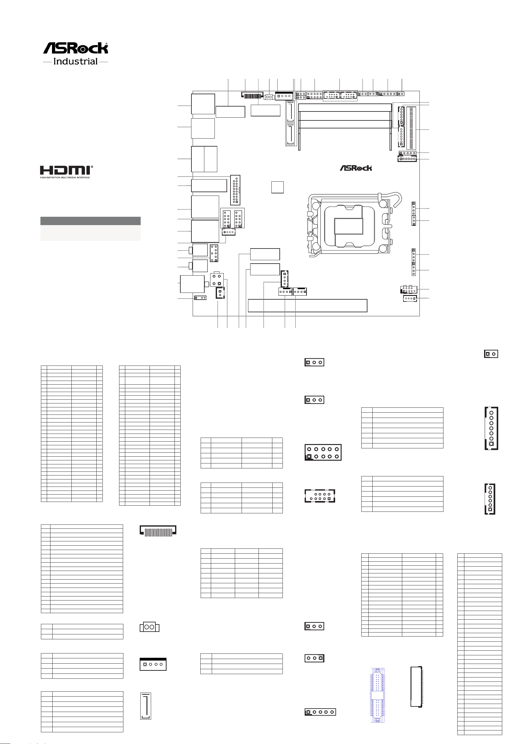
Jumpers and Headers Setting Guide
IMB-1240-WV
IMB-X1240-WV
The terms HDMI® and HDMI High-Denition
Multimedia Interface, and the HDMI logo are
trademarks or registered trademarks of HDMI
Licensing LLC in the United States and other
countries.
Revision History
Date Description
April 19, 2023 First Release
August 14, 2023 Second Release
Industrial
12
11
10
18
3
24
56
79
17 (*Backside:
EDP1)
13 14
18
16
19
22
23
27
28
29
34
33
32 30
25
26
24
20
Mic In
HD_AUDIO1
PCIE1
USB 3.2 Gen2
T: USB3_2
B: USB3_1
Line Out
DC_4PIN1
SATA3 _6 SATA3_5
SPEAKER1
1
HDMI2
LAN1
SPDIF1
1
DDR _B15
DDR _A15
M2_KEYM1
COM1
PWR_COM1
DC_JACK1
USB3_4_9
TO_UPS1
1
M2_KEYE1
M2_KEYM2
PWR_ADAPTER
1
BLT_ VO L1 BLT_PWR1
PNL_PWR1
1
BKT_PWR1
COM3
43
41
40
42
39
36
35
38
37
21
USB2_5_6
M2_B1
EDP_BLT_PWR2
USB2_10_11
DACC1
HEATER1
11
1
1
1
1
JGPIO1
JGPIO_SET1
JGPIO_PWR1
BAT1 SATA_PWR1
1
1
1
1
1
1
1
1
1
CI1_2
CLRMOS1
1
PLED PWRBTN
HDLED RESET
1
PANEL1
SMBUS_TEST1
11
CPU_FAN1
C_FAN1HA
1
1
1
11
LAN2
1
USB 3.2 Gen2
T: USB3_8
B: USB3_7
DP1
HDMI1
PWR_BAT1_SIO_AT1
AT_TEST1_PCIE_PWR1
1
1
15
31
44
45
46
1111
11
1
ESPI1
LVDS 1
BIOS
ROM
1
1
1
* This motherboard supports RS232/422/485 on COM1, 3 ports. Please refer to
the table below for the pin denition. In addition, COM1, 3 ports (RS232/422/485)
can be adjusted in BIOS setup utility > Advanced Screen > Super IO Congura-
tion. You may refer to our user manual for details.
Pin RS232 RS422 RS485
1 DCD TX- RTX-
2 RXD RX+ N/A
3 TXD TX+ RTX+
4 DTR RX- N/A
5 GND GND GND
6 DSR N/A N/A
7RTS N/A N/A
8 CTS N/A N/A
9 PWR PWR PWR
COM1, 3 Ports Pin Denition
** PD (Panel Detection): Connect this pin to
LVDS Panel’s Ground pin to detect Panel
detection.
1
39 40
2
Pin Signal Name Signal Name Pin
1 GND +3.3V 2
3 GND +3.3V 4
5 PERn3 NA 6
7 PERp3 NA 8
9 GND SATA_LED 10
11 PETn3 +3.3V 12
13 PETp3 +3.3V 14
15 GND +3.3V 16
17 PERn2 +3.3V 18
19 PERp2 NA 20
21 GND NA 22
23 PETn2 NA 24
25 PETp2 NA 26
27 GND NA 28
29 PERn1 NA 30
31 PERp1 GND 32
33 GND USB_D+ 34
35 PETn1 USB_D- 36
37 PETp1 GND 38
39 GND SMB_CLK 40
41 PERn0 SMB_DATA 42
43 PERp0 NA 44
45 GND NA 46
47 PETn0 NA 48
49 PETp0 PERST# 50
51 GND CLKREQ# 52
53 PEFCLKn WAKE# 54
55 PEFCLKp NA 56
57 GND NA 58
67 NA NA 68
69 PEDET +3.3V 70
71 GND +3.3V 72
73 GND +3.3V 74
75 GND
1 : M.2 Key-M Socket
(M2_KEYM2)
2 : ESPI Header (ESPI1)
Pin Signal Name
1 GND
2 ESPI_CLK
3 GND
4 ESPI_CS#
5 ESPI_RESET#
6 GND
7 +3V
8 GND
9 SMB_CLK
10 SMB_DATA
11 ESPI_IO0
12 ESPI_IO1
13 ESPI_IO2
14 ESPI_IO3
15 GND
16 +3VSB
17 NA
18 GND
19 ESPI_ALERT#
20 GND
3 : M.2 Key-B Socket
(M2_B1)
•
Special BIOS to support M2X4-SATA-4P
4 :
Battery Connector (BAT1)
5 : SATA Power Output Connector (SATA_PWR1)
6 :
SATA3 Connectors (SATA3_5, SATA3_6)
Pin Signal Name Signal Name Pin
1 NA +3.3V 2
3 GND +3.3V 4
5 GND Full_Card_
Power_o󰀨 6
7 USB_D+ W_DISABLE1# 8
9 USB_D- NA 10
11 GND
21 GND NA 20
23 NA NA 22
25 NA NA 24
27 GND NA 26
29 USB3_RX- NA 28
31 USB3_RX+ UIM_RESET 30
33 GND UIM_CLK 32
35 USB3_TX- UIM_DATA 34
37 USB3_TX+ UIM_PWR 36
39 GND NA 38
41 PERn0 NA 40
43 PERp0 NA 42
45 GND NA 44
47 PETn0 NA 46
49 PETp0 NA 48
51 GND PERST# 50
53 PEFCLKn CLKREQ# 52
55 PEFCLKp WAKE# 54
57 GND NA 56
59 NA NA 58
61 NA NA 60
63 NA NA 62
65 NA NA 64
67 NA NA 66
69 NA NA 68
71 GND +3.3V 70
73 GND +3.3V 72
75 NA +3.3V 74
7 :
Digital Input / Output Power Select
(JGPIO_PWR1)
1-2:
+12V (Default)
2-3:
+5V
8 :
Digital Input / Output
Default Value
Setting (JGPIO_SET1)
1-2: Pull-High
(Default)
2-3: Pull-Low
9 :
Digital Input/Output Pin Header (JGPIO1)
Pin Signal Name Signal Name Pin
1SIO_GP71 GPP_H23 2
3SIO_GP72 GPP_I10 4
5SIO_GP73 GPP_E5 6
7SIO_GP74 GPP_E6 8
9JGPIOPWR_R GND 10
10 : COM Port Headers (COM1, COM3)*
Pin Signal Name Signal Name Pin
1DDCD# RRXD 2
3TTXD DDTR# 4
5GND DDSR# 6
7RRTS# CCTS# 8
9PWR 10
12 : HEATER1 Header (HEATER1)
Pin Signal Name
1 Heater PWR
2 GND
3 NCT
Pin Signal Name
1 +5V
2 GND
3 GND
4 +12V
Pin Signal Name
1 GND
2 SATA-A+
3 SATA-A-
4 GND
5 SATA-B-
6 SATA-B+
7 GND
14 : DACC1
Open: no ACC
Short: ACC (Default)
• Auto clear CMOS when system boot improperly.
15 : Backlight Volume Control
(BLT_VOL1)
16 :
Inverter Power Control Wafer
(BLT_PWR1)
Pin Signal Name
1 GPIO_VOL_UP
2 GPIO_VOL_DW
3 PWRDN
4 BLT_UP
5 BLT_DW
6 GND
7 GND
Pin Signal Name
1 GND
2 GND
3 CON_LBKLT_CTL
4 CON_LBKLT_EN
5 LCD_BLT_VCC
6 LCD_BLT_VCC
17** : LVDS Panel Connector
(LVDS1)
Pin Signal Name Signal Name Pin
1 LCD_VCC LCD_VCC 2
3 +3.3V N/A 4
5 N/A LVDS_A_DATA0# 6
7 LVDS_A_DATA0 PD (Panel Detection) 8
9 LVDS_A_DATA1# LVDS_A_DATA1 10
11 GND LVDS_A_DATA2# 12
13 LVDS_A_DATA2 GND 14
15 LVDS_A_DATA3# LVDS_A_DATA3 16
17 GND LVDS_A_CLK# 18
19 LVDS_A_CLK GND 20
21 LVDS_B_DATA0# LVDS_B_DATA0 22
23 GND LVDS_B_DATA1# 24
25 LVDS_B_DATA1 GND 26
27 LVDS_B_DATA2# LVDS_B_DATA2 28
29 DPLVDD_EN LVDS_B_DATA3# 30
31 LVDS_B_DATA3 GND 32
33 LVDS_B_CLK# LVDS_B_CLK 34
35 GND CON_LBKLT_EN 36
37 CON_LBKLT_CTL LCD_BLT_VCC 38
39 LCD_BLT_VCC LCD_BLT_VCC 40
13 : Backlight Power Select
(LCD_BLT_VCC) (BKT_PWR1)
1-2: LCD_BLT_VCC: +5V (Default)
2-3: LCD_BLT_VCC: +12V
4-5: LCD_BLT_VCC: DC_IN
Pin Signal Name
1 NA
2 GND
3 eDP_TX#3_CON
4 eDP_TX3_CON
5 GND
6 eDP_TX#2_CON
7 eDP_TX2_CON
8 GND
9 eDP_TX#1_CON
10 eDP_TX1_CON
11 GND
12 eDP_TX#0_CON
13 eDP_TX0_CON
14 GND
15 eDP_AUX_CON
16 eDP_AUX#_CON
17 GND
18 LCD_VCC
19 LCD_VCC
20 LCD_VCC
21 LCD_VCC
22 NA
23 GND
24 GND
25 GND
26 GND
27 eDP_HPD_CON
28 GND
29 GND
30 GND
31 GND
32 eDP_BKLTEN
33 eDP_BKLTCTL_R
34 SMB_DATA_MAIN
35 SMB_CLK_MAIN
36 LCD_BLT_VCC
37 LCD_BLT_VCC
38 LCD_BLT_VCC
39 LCD_BLT_VCC
40 NA
** eDP Connector
(on the Backside
of PCB)
120
Pin Signal Name
1 +BAT
2 GND
1 4
1
7
123
123
2 10
1 9
19
210
1 2
1 5
321
1
1
7
6
1 2 3
40
1
EDP1
40
1
12
BAT1
Installation of ROM Socket
•
Do not apply force to the actuator cover after ic inserted.
•
Do not apply force to actuator cover when it is opening over 120
degree, Otherwise, the actuator cover may be broken.
•
The yellow dot (Pin1) on the ROM must be installed at pin1 position of
the socket (white arrow area).
•
Make sure the white dot on the ROM is installed outwards of the
socket.
•
For further details of how to install ROM, please refer to ASRI website.
Warning: If the installation does not follow as the picture, then it
may cause severe damage to chipset & MB.
Industrial
12
11
10
18
3
24
56
79
17 (*Backside:
EDP1)
13 14
18
16
19
22
23
27
28
29
34
33
32 30
25
26
24
20
Mic In
HD_AUDIO1
PCIE1
USB 3.2 Gen2
T: USB3_2
B: USB3_1
Line Out
DC_4PIN1
SATA3 _6 SATA3_5
SPEAKER1
1
HDMI2
LAN1
SPDIF1
1
DDR _B15
DDR _A15
M2_KEYM1
COM1
PWR_COM1
DC_JACK1
USB3_4_9
TO_UPS1
1
M2_KEYE1
M2_KEYM2
PWR_ADAPTER
1
BLT_ VO L1 BLT_PWR1
PNL_PWR1
1
BKT_PWR1
COM3
43
41
40
42
39
36
35
38
37
21
USB2_5_6
M2_B1
EDP_BLT_PWR2
USB2_10_11
DACC1
HEATER1
11
1
1
1
1
JGPIO1
JGPIO_SET1
JGPIO_PWR1
BAT1 SATA_PWR1
1
1
1
1
1
1
1
1
1
CI1_2
CLRMOS1
1
PLED PWRBTN
HDLED RESET
1
PANEL1
SMBUS_TEST1
11
CPU_FAN1
C_FAN1HA
1
1
1
11
LAN2
1
USB 3.2 Gen2
T: USB3_8
B: USB3_7
DP1
HDMI1
PWR_BAT1_SIO_AT1
AT_TEST1_PCIE_PWR1
1
1
15
31
44
45
46
1111
11
1
ESPI1
LVDS 1
BIOS
ROM
1
1
1
18 : Panel Power Select
(LCD_VCC) (PNL_PWR1)
1-2: LCD_VCC: +3V (Default)
2-3: LCD_VCC: +5V
4-5: LCD_VCC: +12V
19 :
Inverter Power Control Wafer
(EDP_BLT_PWR2)
Pin Signal Name
1 GND
2 GND
3 eDP_LBKLT_CTL
4 eDP_LBKLT_EN
5 +12_FUSE
6 +12_FUSE
20 : Chassis Intrusion Header (CI1_2)
Pin Signal Name
1 CI1 Signal
2 GND
3 CI2 Signal
4 GND
21 : Clear CMOS Header (CLRMOS1)
1-2: Normal (Default)
2-3: Clear CMOS
22 :
PWR_BAT1_SIO_AT1
Pin Signal Name
1 PWR_BAT1:
Open: Normal
Short: Charge Battery2
3 SIO_AT1:
Open: ATX Mode
Short: AT Mode4
23 : AT_TEST1_PCIE_PWR1
24 : System Panel Header (PANEL1)
Pin Signal Name
1AT_TEST1
(For Internal Test)
2
3PCIE_PWR1
(For VGA Power Card Only):
Pin3: PSON#
Pin4: GND
4
Pin Signal Name Signal Name Pin
1 HDLED+ PLED+ 2
3 HDLED- PLED- 4
5 GND PWRBTN# 6
7 RESET# GND 8
9 GND 10
25 : SMBUS_TEST1
Pin Signal Name
1 GPP_E7
2 SMB_CLK_MAIN
3 SMB_DATA_MAIN
4 GND
26 :
CPU FAN Connector (+12V) (CPU_FAN1)
27 :
Chassis FAN Connector (+12V)
(CHA_FAN1)
Pin Signal Name
1 GND
2 +12V
3 CPU_FAN_SPEED
4 FAN_SPEED_CONTROL
Pin Signal Name
1 GND
2 +12V
3 CHA_FAN_SPEED
4 FAN_SPEED_CONTROL
28 : Power Adapter (PRW_ADAPTER)
Pin Signal Name
1 GND
2 5VA_CONTROL
35VA
4 GND
29 :
M.2 Key-M Socket
(M2_KEYM1)
30 :
M.2 Key-ESocket
(M2_KEYE1)
Pin Signal Name Signal Name Pin
1 GND +3.3V 2
3 USB_D+ +3.3V 4
5 USB_D- NA 6
7 GND NA 8
9 CNV_WGR_D1- CNV_RF_RESET 10
11 CNV_WGR_D1+ NA 12
13 GND MODEM_CLKREQ 14
15 CNV_WGR_D0- NA 16
17 CNV_WGR_D0+ GND 18
19 GND NA 20
21 CNV_WGR_CLK- CNV_BRI_RSP 22
23 CNV_WGR_CLK+
33 GND CNV_BGI_DT 32
35 PETp CNV_RGI_RSP 34
37 PETn CNV_BRI_DT 36
39 GND NA 38
41 PERp NA 40
43 PERn NA 42
45 GND NA 44
47 PEFCLKp NA 46
49 PEFCLKn NA 48
51 GND SUSCLK 50
53 CLKREQ# PERST0# 52
55 WAKE# W_DISABLE1# 54
57 GND W_DISABLE2# 56
59 CNV_WT_D1- SMB_DATA 58
61 CNV_WT_D1+ SMB_CLK 60
63 GND NA 62
65 CNV_WT_D0- CLKIN_XTAL_LCP 64
67 CNV_WT_D0+ NA 66
69 GND NA 68
71 CNV_WT_CLK- NA 70
73 CNV_WT_CLK+ +3.3V 72
75 GND +3.3V 74
Pin Signal Name Signal Name Pin
1 GND +3.3V 2
3 GND +3.3V 4
5 PERn3 NA 6
7 PERp3 NA 8
9 GND SATA_LED 10
11 PETn3 +3.3V 12
13 PETp3 +3.3V 14
15 GND +3.3V 16
17 PERn2 +3.3V 18
19 PERp2 NA 20
21 GND NA 22
23 PETn2 NA 24
25 PETp2 NA 26
27 GND NA 28
29 PERn1 NA 30
31 PERp1 GND 32
33 GND USB_D+ 34
35 PETn1 USB_D- 36
37 PETp1 GND 38
39 GND SMB_CLK 40
41 PERn0 SMB_DATA 42
43 PERp0 NA 44
45 GND NA 46
47 PETn0 NA 48
49 PETP0 PERST# 50
51 GND CLKREQ# 52
53 PEFCLKn WAKE# 54
55 PEFCLKp NA 56
57 GND NA 58
67 NA NA 68
69 PEDET +3.3V 70
71 GND +3.3V 72
73 GND +3.3V 74
75 GND
31 : 4-pin ATX PWR Connector
(DC_4PIN1)
1-2: GND
3-4: DC Input (12V only)
32 : 2-pin UPS Module Power Input Connector
(TO_UPS1)
Pin Signal Name
1 GND
2 DC Input
33 :
SPDIF Header (SPDIF1)
Pin Signal Name
1 +5V
2
3 SPDIF_OUT
4 GND
34 : DC Jack (DC_JACK1)
35 :
Audio Jack : Pink - Mic In
36 :
Front Panel Audio Header (HD_AUDIO1)
Pin Signal Name Signal Name Pin
1 MIC2_L GND 2
3 MIC2_R 4
5 OUT2_R MIC_RET 6
7 J_SENSE 8
9 OUT2_L OUT_RET 10
37 :
Audio Jack : Green - Line Out
38 : 3W Audio AMP Output Wafer (SPEAKER1)
Pin Signal Name
1 OUTLN
2 OUTLP
3 OUTRP
4 OUTRN
39 :
RJ45 LAN Port (LAN1)
40 : USB2.0 Headers (USB2_5_6, USB2_10_11)
Pin Signal Name Signal Name Pin
1 USB_PWR USB_PWR 2
3 P- P- 4
5 P+ P+ 6
7 GND GND 8
9 DUMMY 10
41 :
RJ45 LAN Port (LAN2)
42 :
HDMI Port (HDMI2)
43 :
USB3.2 Gen1 Header (USB3_4_9)
Pin Signal Name Signal Name Pin
1 DUMMY IntA_PA_D+ 2
3 IntA_PB_D+ IntA_PA_D- 4
5 IntA_PB_D- GND 6
7 GND IntA_PA_SSTX+ 8
9 IntA_PB_SSTX+ IntA_PA_SSTX- 10
11 IntA_PB_SSTX- GND 12
13 GND IntA_PA_SSRX+ 14
15 IntA_PB_SSRX+ IntA_PA_SSRX- 16
17 IntA_PB_SSRX- Vbus 18
19 Vbus 20
44 :
Top : DisplayPort (DP1)
Bottom : HDMI Port (HDMI1)
45 :
Top :
USB3.2 Gen2
Port (USB3_8)
Bottom :
USB3.2 Gen2
Port (USB3_7)
46 : Top :
USB3.2 Gen2
Port (USB3_2)
Bottom :
USB3.2 Gen2
Port (USB3_1)
Back Side :
SIM Card Socket (SIM1)
eDP Connector (EDP1, refer to No. 17)
1 5
1
4
1
4
1
4
1 9
2 10
4 1
3
2
1
1
4
1
4
1
4
2 1
4 3
1 4
12
9
10
1 4
1
2
910
12
1920
1 6
1
2

This manual suits for next models

1

Other ASRock Industrial Computer Hardware manuals

ASRock Industrial NUC-1335UE/D4 User manual

ASRock Industrial

ASRock Industrial NUC-1335UE/D4 User manual

ASRock Industrial CAB-1001 Service manual

ASRock Industrial

ASRock Industrial CAB-1001 Service manual

ASRock Industrial SBC-373-WT Service manual

ASRock Industrial

ASRock Industrial SBC-373-WT Service manual

ASRock Industrial IMB-1314 Service manual

ASRock Industrial

ASRock Industrial IMB-1314 Service manual

ASRock Industrial iBOX 1300/D4 Series User manual

ASRock Industrial

ASRock Industrial iBOX 1300/D4 Series User manual

ASRock Industrial 4X4 BOX-7840U User manual

ASRock Industrial

ASRock Industrial 4X4 BOX-7840U User manual

ASRock Industrial NUC-1360P/D4 User manual

ASRock Industrial

ASRock Industrial NUC-1360P/D4 User manual

ASRock Industrial NUC BOX-N97 User manual

ASRock Industrial

ASRock Industrial NUC BOX-N97 User manual

ASRock Industrial IMB-1314 User manual

ASRock Industrial

ASRock Industrial IMB-1314 User manual

ASRock Industrial IMB-X1314 Service manual

ASRock Industrial

ASRock Industrial IMB-X1314 Service manual

ASRock Industrial CAB-202 Service manual

ASRock Industrial

ASRock Industrial CAB-202 Service manual

ASRock Industrial SOM-P104 Service manual

ASRock Industrial

ASRock Industrial SOM-P104 Service manual

ASRock Industrial SBC-250J Service manual

ASRock Industrial

ASRock Industrial SBC-250J Service manual

ASRock Industrial iBOX ADL-N Series User manual

ASRock Industrial

ASRock Industrial iBOX ADL-N Series User manual

ASRock Industrial NUC-N97 User manual

ASRock Industrial

ASRock Industrial NUC-N97 User manual

ASRock Industrial IMB-1005 User manual

ASRock Industrial

ASRock Industrial IMB-1005 User manual

ASRock Industrial SBC-250 User manual

ASRock Industrial

ASRock Industrial SBC-250 User manual

ASRock Industrial SBC-261J User manual

ASRock Industrial

ASRock Industrial SBC-261J User manual

ASRock Industrial NUC BOX-J6412 User manual

ASRock Industrial

ASRock Industrial NUC BOX-J6412 User manual

ASRock Industrial NUC BOX-1260P User manual

ASRock Industrial

ASRock Industrial NUC BOX-1260P User manual

ASRock Industrial IMB-1714 User manual

ASRock Industrial

ASRock Industrial IMB-1714 User manual

ASRock Industrial SBC-260 User manual

ASRock Industrial

ASRock Industrial SBC-260 User manual

ASRock Industrial IMB-1239-WV User manual

ASRock Industrial

ASRock Industrial IMB-1239-WV User manual

ASRock Industrial SBC-250J Service manual

ASRock Industrial

ASRock Industrial SBC-250J Service manual

Popular Computer Hardware manuals by other brands

Nintendo Ultra64 Programmer's guide

Nintendo

Nintendo Ultra64 Programmer's guide

TDK DPX Series DPX161990DT-8003B1 Specifications

TDK

TDK DPX Series DPX161990DT-8003B1 Specifications

Supermicro SBI-7127R-S6 user manual

Supermicro

Supermicro SBI-7127R-S6 user manual

Omron F3SP-U3P-TGR datasheet

Omron

Omron F3SP-U3P-TGR datasheet

Bridgeworks a102 Hardware manual

Bridgeworks

Bridgeworks a102 Hardware manual

Qsonica SONICATOR S-4000 Operation manual

Qsonica

Qsonica SONICATOR S-4000 Operation manual

Diamond Flower Ink MG-150 user manual

Diamond Flower Ink

Diamond Flower Ink MG-150 user manual

CYP AU-11CD-4K22 Operation manual

CYP

CYP AU-11CD-4K22 Operation manual

evertz 2400PSUA-8 instruction manual

evertz

evertz 2400PSUA-8 instruction manual

Spectrum Digital XDS560R installation guide

Spectrum Digital

Spectrum Digital XDS560R installation guide

Renesas R8C/23 quick start

Renesas

Renesas R8C/23 quick start

Milesight VS34x user guide

Milesight

Milesight VS34x user guide

COMPUTER inspirations RGB MR-16 LED PCB ASSEMBLY INSTRUCTIONS & TECHNICAL MANUAL

COMPUTER inspirations

COMPUTER inspirations RGB MR-16 LED PCB ASSEMBLY INSTRUCTIONS & TECHNICAL MANUAL

Texas Instruments TSC2007EVM user guide

Texas Instruments

Texas Instruments TSC2007EVM user guide

Siemens SIMATIC NET CP 1623 operating instructions

Siemens

Siemens SIMATIC NET CP 1623 operating instructions

Seco SBC-C90 user manual

Seco

Seco SBC-C90 user manual

Dwin TransVision 3 operating instructions

Dwin

Dwin TransVision 3 operating instructions

D-Link DUB-1320 Quick install guide

D-Link

D-Link DUB-1320 Quick install guide

manuals.online logo
manuals.online logoBrands
  • About & Mission
  • Contact us
  • Privacy Policy
  • Terms and Conditions

Copyright 2025 Manuals.Online. All Rights Reserved.