manuals.online logo
Brands
  1. Home
  2. •
  3. Brands
  4. •
  5. ASRock Industrial
  6. •
  7. Motherboard
  8. •
  9. ASRock Industrial STX-1000B Service manual

ASRock Industrial STX-1000B Service manual

17 : LVDS Panel Connector
18 : BL2
Open : Protect LCD_VCC
Short : No Protect LCD_VCC
19 : 3W Audio AMP Output Wafer
20 : M.2 Key-E Socket (M2_E1)
21 : SPDIF Header
22 : SATA3 Connectors (SATA3_1, SATA3_2
)
(SATA3_2 is share with M2_B1)
7 : SATA Power Output Connector
8 :
Front Panel Audio Header
Audio Jacks
9 : Pink - Mic In
10 : Green - Line Out
11 : USB3.0 Port (USB3_1)
12 : USB3.0 Port (USB3_2)
13 :
Backlight Power Connector
(BLT_PWR1)
14 : Panel Power Select
(LCD_VCC) (PNL_PWR1)
1-2 : LCD_VCC : +3V
2-3 : LCD_VCC : +5V
4-5 : LCD_VCC : +12V
15 : Backlight Power Select
(LCD_BLT_VCC) (BKT_PWR1)
1-2 : LCD_BLT_VCC : +5V
2-3 : LCD_BLT_VCC : +12V
4-5 : LCD_BLT_VCC : DC_IN
16 : BL1
Open : Protect LCD_BLT_VCC
Short : No Protect LCD_BLT_VCC
1 : 4-pin DC-in PWR Connector (Input +9V~+24V)
& UPS Module Power Output Connector
Pin1 and Pin4: GND
Pin2 and Pin3: DC Input
2 : COM Port Headers (COM2, 3)
3 : USB2.0 Header
(
USB2_4)
4 : ATX/AT Mode Select (PWR_JP1)
1-2 : AT Mode
2-3 : ATX Mode
5 :
4-Pin CPU FAN Connector
(+12V)
6 :
System Panel Header
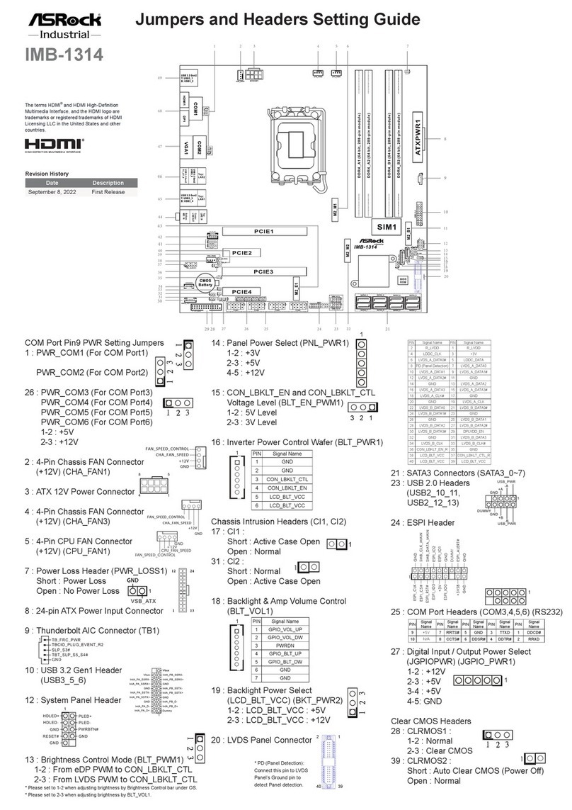
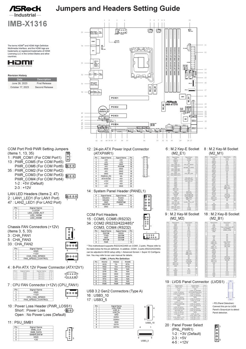
Jumpers and Headers Setting Guide
STX-1000B
STX-1000J
STX-1000D
STX-1000BR
STX-1000JR
STX-1000DR
STX-1000DR-NF
STX-1000
Mic In
BIOS
ROM
1
HD_AUDIO1
DC_JACK1
LVDS1
1
SPEAKER1
1
USB 2.0
T: USB0
B: USB1
LAN1
Line Out
SPDIF1
1
HDLED RESET
PLED PWRBTN
PANEL1
1
Industrial
SATA3_2
CLRMOS1
1
BLT_PWM1
1
PWR_JP1
1
1
TPM1
1
JGPIO1
1
BLT_VOL1
DISPLAY1
1
LPC1
SATA3_1
CPU_FAN1
SATA_PWR1
1
BL2
DDR4_A1
1
PNL_PWR1
BAT1
1
PWR_BAT1
DISPLAY2
USB 2.0
T: USB2
B: USB3
USB3_1
USB3_2
FROM_UPS1
1
COM3
1
COM2
1
1
USB2_4
1
BL1
1
BLT_PWR1
1
BKT_PWR1
M2_E1
M2_B1
USB3_3_4
1
CLRMOS2
1
CI1
1
CI2
1
BUZZ1
JGPIO_PWR1
1
JGPIO_SET1
1
LAN2
SATA3_2 SATA3_1
CPU_FAN_SPEED
FAN_SPEED_CONTROL
4 3 2 1
PIN Signal Name PIN Signal Name
2 LCD_VCC 1 LCD_VCC
4 LDDC_CLK 3 +3.3V
6 LVDS_A_DATA0# 5 LDDC_DATA
8 GND 7 LVDS_A_DATA0
10 LVDS_A_DATA1 9 LVDS_A_DATA1#
12 LVDS_A_DATA2# 11 GND
14 GND 13 LVDS_A_DATA2
16 LVDS_A_DATA3 15 LVDS_A_DATA3#
18 LVDS_A_CLK# 17 GND
20 GND 19 LVDS_A_CLK
22 LVDS_B_DATA0 21 LVDS_B_DATA0#
24 LVDS_B_DATA1# 23 GND
26 GND 25 LVDS_B_DATA1
28 LVDS_B_DATA2 27 LVDS_B_DATA2#
30 LVDS_B_DATA3# 29 DPLVDD_EN
32 GND 31 LVDS_B_DATA3
34 LVDS_B_CLK 33 LVDS_B_CLK#
36 CON_LBKLT_EN 35 GND
38 LCD_BLT_VCC 37 CON_LBKLT_CTL
40 LCD_BLT_VCC 39 LCD_BLT_VCC
1
1
1
PIN RS232 RS422 RS485
1 DCD TX- RTX-
2 RXD RX+ N/A
3 TXD TX+ RTX+
4 DTR RX- N/A
5 GND GND GND
6 DSR N/A N/A
7 RTS N/A N/A
8 CTS N/A N/A
9 RI N/A N/A
10 NC NC NC
* This motherboard supports RS232/422/485 on COM3 port. Please
refer to below table for the pin denition. In addition, COM3 port
(RS232/422/485) can be adjusted in BIOS setup utility > Advanced
Screen > Super IO Conguration. You may refer to our user manual
for details.
COM3 Port Pin Denition
PIN Signal
Name PIN Signal
Name PIN Signal
Name PIN Signal
Name PIN Signal
Name
10 NC 8CCTS# 6DDSR# 4DDTR# 2RRXD
9RRI# 7RRTS# 5GND 3TTXD 1DDCD#
2
1
1
USB_PWR
P- P+ GND
GND
RESET#
PWRBTN#
PLED-
PLED+
GND
HDLED-
HDLED+
1
GND
GND
+5V
+12V
1
GND
PIN Signal
Name PIN Signal
Name PIN Signal
Name PIN Signal
Name PIN Signal
Name PIN Signal
Name
6LCD_BLT_
VCC 5
LCD_
BLT_
VCC
4
CON_
LBKLT_
EN
3
CON_
LBKLT_
CTL
2 GND 1 GND
1
139
40
2
1
PIN Signal
Name PIN Signal
Name PIN Signal
Name PIN Signal
Name
1OUTLN 2OUTLP 3GOUTRP 4OUTRN
N/A
*15G06M088001AK*
P/ N: 15G06M088001AK V1.1
30 :
Digital Input / Output
Default Value Setting
(JGPIO_SET1)
1-2 : Pull-High
2-3 : Pull-Low
31
: Digital Input / Output Pin Header
(JGPIO1)
32 : Clear CMOS Headers
CLRMOS1
1-2 : Normal
2-3 : Clear CMOS
CLRMOS2
Open : Normal
Short : Auto Clear CMOS (Power O󰀨)
33 : Chassis Intrusion Headers
CI1
Close : Active case open
Open : Normal
Cl2
Close : Normal
Open : Active case open
34 : USB2.0 Ports (USB2_2_3)
35 : M.2 Key-B Socket
(M2_B1)
23 :
Backlight Control Level
(CON_LBKLT_CTL) (BLT_PWM1)
1-2 : eDP Control
2-3 : CH7511B Control
24 : USB3.0 Header
(
USB3_3_4)
25 : Backlight Volume Control
(BLT_VOL1)
26 : SPI TPM Header
27 : LPC Header
28 : PWR_BAT1
Open : Normal
Short : Charge Battery
29 : Digital Input / Output Power Select
(JGPIOPWR) (JGPIO_PWR1)
1-2 : +12V
2-3 : +5V
STX-1000
Mic In
BIOS
ROM
1
HD_AUDIO1
DC_JACK1
LVDS1
1
SPEAKER1
1
USB 2.0
T: USB0
B: USB1
LAN1
Line Out
SPDIF1
1
HDLED RESET
PLED PWRBTN
PANEL1
1
Industrial
SATA3_2
CLRMOS1
1
BLT_PWM1
1
PWR_JP1
1
1
TPM1
1
JGPIO1
1
BLT_VOL1
DISPLAY1
1
LPC1
SATA3_1
CPU_FAN1
SATA_PWR1
1
BL2
DDR4_A1
1
PNL_PWR1
BAT1
1
PWR_BAT1
DISPLAY2
USB 2.0
T: USB2
B: USB3
USB3_1
USB3_2
FROM_UPS1
1
COM3
1
COM2
1
1
USB2_4
1
BL1
1
BLT_PWR1
1
BKT_PWR1
M2_E1
M2_B1
USB3_3_4
1
CLRMOS2
1
CI1
1
CI2
1
BUZZ1
JGPIO_PWR1
1
JGPIO_SET1
1
LAN2
1
ID IntA_P_D+
IntA_P_D-
GN D
IntA_P_SSTX+
IntA_P_SSTX-
GN D
IntA_P_SSRX+
Vbus
IntA_P_D+
IntA_P_D-
GN D
IntA_P_SSTX+
IntA_P_SSTX-
GN D
IntA_P_SSRX+
IntA_P_SSRX-
Vbus
IntA_P_SSRX-
1
PIN Signal
Name PIN Signal
Name PIN Signal
Name PIN Signal
Name PIN Signal
Name PIN Signal
Name PIN Signal
Name
7 GND 6 GND 5 BLT_DW 4 BLT_UP 3 PWRDN 2 GPIO_
VOL_DW 1GPIO_
VOL_UP
1
GND
SMB_DATA_MAIN
LAD2
LAD1
GND
S_PWRDWN#
SERIRQ#
GND
PCICLK
PCIRST#
LAD3
+3V
LAD0
+3VSB
GND
FRAME SMB_CLK_MAIN
PIN Signal
Name PIN Signal
Name PIN Signal
Name PIN Signal
Name PIN Signal Name
2SIO_GP30 4SIO_GP31 6SIO_GP32 8SIO_GP33 10 GND
1SIO_GP34 3SIO_GP35 5SIO_GP36 7SIO_GP37 9JGPIO_PWR
1
Signal
GND
36 : USB2.0 Ports (USB2_0_1)
37 : Battery Connector
38 :
RJ45 LAN Port (LAN2)
39 : RJ45 LAN Port (LAN1)
40 : DisplayPort (DISPLAY2)
41 : DisplayPort (DISPLAY1)
42 : DC Jack (DC_JACK1)
Back Side:
SIM Card Socket (SIM1)
eDP Connector (EDP1)
PIN Signal Name
40 NA
39 LCD_BLT_VCC
38 LCD_BLT_VCC
37 LCD_BLT_VCC
36 LCD_BLT_VCC
35 NA
34 NA
33 CON_LBKLT_CTL
32 CON_LBKLT_EN
31 GND
30 GND
29 GND
28 GND
27 eDP_HPD_CON
26 GND
25 GND
24 GND
23 GND
22 NA
21 LCD_VCC
20 LCD_VCC
19 LCD_VCC
18 LCD_VCC
17 GND
16 eDP_AUX#_CON
15 eDP_AUX_CON
14 GND
13 eDP_TX0_CON
12 eDP_TX#0_CON
11 GND
10 eDP_TX1_CON
9 eDP_TX#1_CON
8 GND
7 eDP_TX2_CON
6 eDP_TX#2_CON
5 GND
4 eDP_TX3_CON
3 eDP_TX#3_CON
2 GND
1 NA
40
1
EDP1

This manual suits for next models

6

Other ASRock Industrial Motherboard manuals

ASRock Industrial IMB-1314 Service manual

ASRock Industrial

ASRock Industrial IMB-1314 Service manual

ASRock Industrial IMB-R1000 User manual

ASRock Industrial

ASRock Industrial IMB-R1000 User manual

ASRock Industrial IMB-1006 User manual

ASRock Industrial

ASRock Industrial IMB-1006 User manual

ASRock Industrial IMB-X1314 Service manual

ASRock Industrial

ASRock Industrial IMB-X1314 Service manual

ASRock Industrial IMB-X1231 User manual

ASRock Industrial

ASRock Industrial IMB-X1231 User manual

ASRock Industrial IMB-1315 User manual

ASRock Industrial

ASRock Industrial IMB-1315 User manual

ASRock Industrial SOM-P104 User manual

ASRock Industrial

ASRock Industrial SOM-P104 User manual

ASRock Industrial IMB-X1314 User manual

ASRock Industrial

ASRock Industrial IMB-X1314 User manual

ASRock Industrial IMB-151D-WF User manual

ASRock Industrial

ASRock Industrial IMB-151D-WF User manual

ASRock Industrial 4X4-7840U-1U User manual

ASRock Industrial

ASRock Industrial 4X4-7840U-1U User manual

ASRock Industrial IMB-1316 User manual

ASRock Industrial

ASRock Industrial IMB-1316 User manual

ASRock Industrial IMB-1314 Service manual

ASRock Industrial

ASRock Industrial IMB-1314 Service manual

ASRock Industrial IMB-1234 Service manual

ASRock Industrial

ASRock Industrial IMB-1234 Service manual

ASRock Industrial 3U10G-F User manual

ASRock Industrial

ASRock Industrial 3U10G-F User manual

ASRock Industrial IMB-X1316 User manual

ASRock Industrial

ASRock Industrial IMB-X1316 User manual

ASRock Industrial IMB-1232-WV User manual

ASRock Industrial

ASRock Industrial IMB-1232-WV User manual

ASRock Industrial IMB-1234 User manual

ASRock Industrial

ASRock Industrial IMB-1234 User manual

ASRock Industrial IMB-1230 User manual

ASRock Industrial

ASRock Industrial IMB-1230 User manual

ASRock Industrial IMB-157 User manual

ASRock Industrial

ASRock Industrial IMB-157 User manual

ASRock Industrial SOM-P104 Service manual

ASRock Industrial

ASRock Industrial SOM-P104 Service manual

ASRock Industrial IMB-1714 Service manual

ASRock Industrial

ASRock Industrial IMB-1714 Service manual

ASRock Industrial NUC-J6412 User manual

ASRock Industrial

ASRock Industrial NUC-J6412 User manual

ASRock Industrial IMB-X1712 User manual

ASRock Industrial

ASRock Industrial IMB-X1712 User manual

ASRock Industrial IMB-V2000 User manual

ASRock Industrial

ASRock Industrial IMB-V2000 User manual

Popular Motherboard manuals by other brands

MSI P45D3Neo3 Series manual

MSI

MSI P45D3Neo3 Series manual

Biostar G41 HD Bios setup manual

Biostar

Biostar G41 HD Bios setup manual

ATEQ VT30 Quick start user manual

ATEQ

ATEQ VT30 Quick start user manual

ASROCK 890GX EXTREME4 manual

ASROCK

ASROCK 890GX EXTREME4 manual

Murata 1GC quick start guide

Murata

Murata 1GC quick start guide

DFI CA900-B user manual

DFI

DFI CA900-B user manual

Intel DQ57TM Product guide

Intel

Intel DQ57TM Product guide

MSI B75MA-E2 user manual

MSI

MSI B75MA-E2 user manual

DFI CP100-NRM user manual

DFI

DFI CP100-NRM user manual

MSI Z490-A PRO quick start

MSI

MSI Z490-A PRO quick start

Asus Crossblade Ranger manual

Asus

Asus Crossblade Ranger manual

Waveshare Open32F0-D user manual

Waveshare

Waveshare Open32F0-D user manual

AOpen AX45 PRO-533 Online manual

AOpen

AOpen AX45 PRO-533 Online manual

OEM ITX-780G2 user manual

OEM

OEM ITX-780G2 user manual

Texas Instruments TAS5101SE user guide

Texas Instruments

Texas Instruments TAS5101SE user guide

Asus P8B75-M/CSM user manual

Asus

Asus P8B75-M/CSM user manual

mATX AIMB-562 Series user manual

mATX

mATX AIMB-562 Series user manual

Winmate IK70 user manual

Winmate

Winmate IK70 user manual

manuals.online logo
manuals.online logoBrands
  • About & Mission
  • Contact us
  • Privacy Policy
  • Terms and Conditions

Copyright 2025 Manuals.Online. All Rights Reserved.