manuals.online logo
Brands
  1. Home
  2. •
  3. Brands
  4. •
  5. ASROCK Rack
  6. •
  7. Computer Hardware
  8. •
  9. ASROCK Rack SPC741D8UD-2T User manual

ASROCK Rack SPC741D8UD-2T User manual

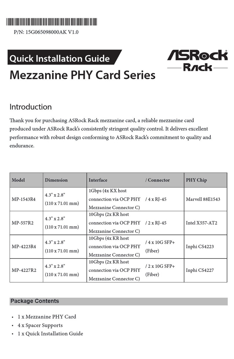
SPC741D8UD-2T | SPC741D8UD-2T/X550
Quick Installation Guide
www.asrockrack.com SPC741D8UD-2T SPC741D8UD-2T/X550
4
2
P/N: 15G065263000AK V1.0
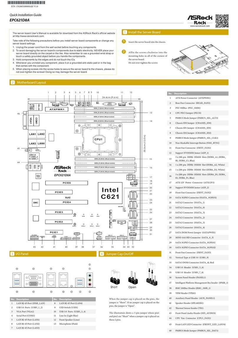
Motherboard Layout
Jumper Settings
The server board User's Manual is available for download from the ASRock Rack's o󰀩cial website
at http://www.asrockrack.com.
Take note of the following precautions before you install server board components or change any
server board settings.
1. Unplug the power cord from the wall socket before touching any components.
2. To avoid damaging the server board’s components due to static electricity, NEVER place your
server board directly on the carpet or the like. Also remember to use a grounded wrist strap or
touch a safety grounded object before you handle the components.
3. Hold components by the edges and do not touch the ICs.
4. Whenever you uninstall any component, place it on a grounded anti-static pad or in the bag
that comes with the component.
5. When placing screws into the screw holes to secure the server board to the chassis, please do
not over-tighten the screws! Doing so may damage the server board.
When the jumper cap is placed on the pins, the jumper
is “Short”. If no jumper cap is placed on the pins, the
jumper is “Open”.
e illustration shows a 3-pin jumper whose pin1 and
pin2 are “Short” when a jumper cap is placed on these 2
pins.
*15G065263000AK*
Install the Server Board1
1Insert the server board into the chassis.
2Affix t he screws clockwise into the
mounting holes in all of the corners of
the server board.
Do not over-tighten the screws
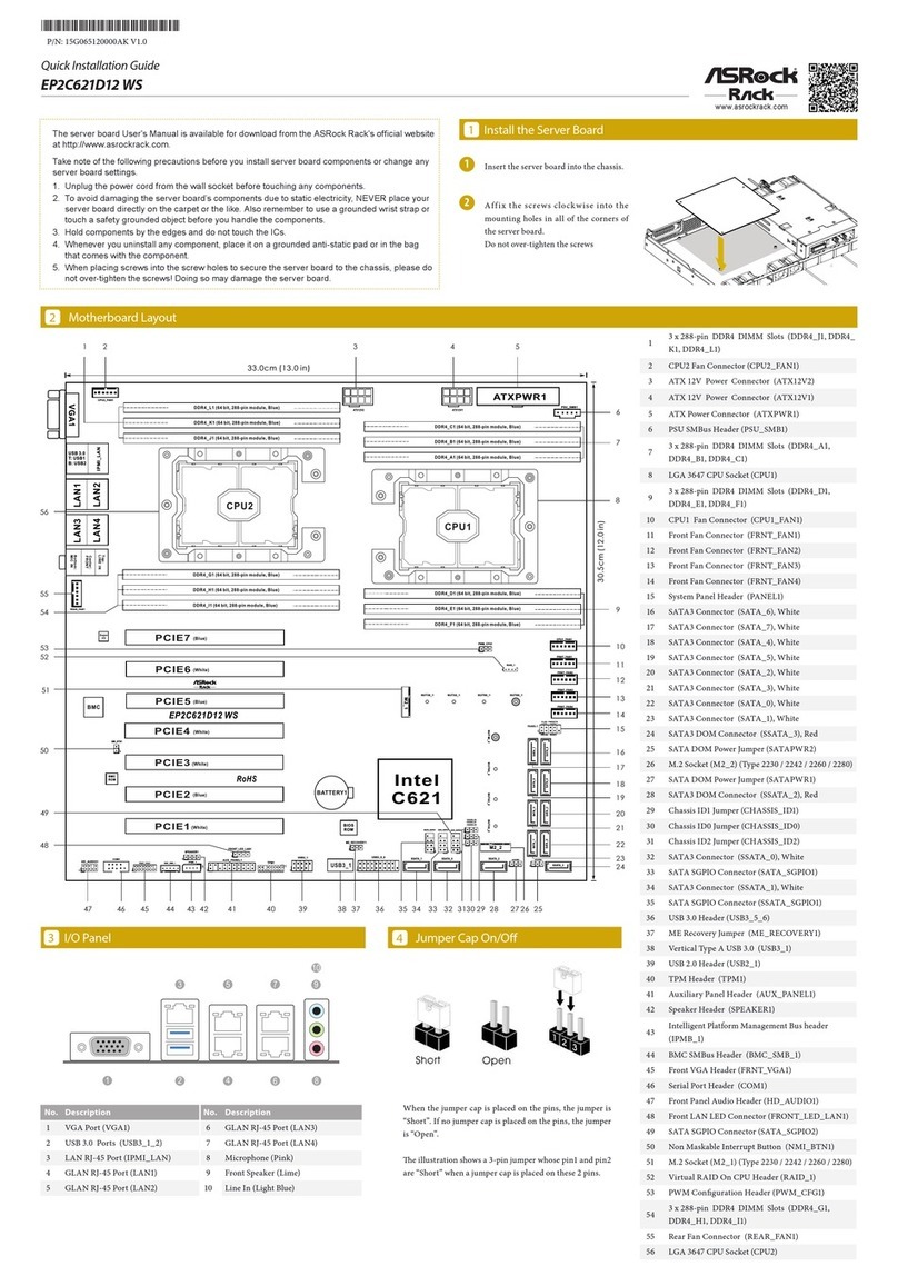
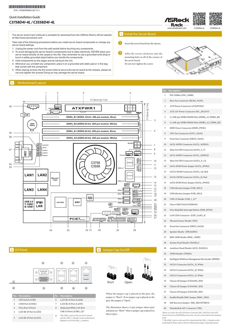
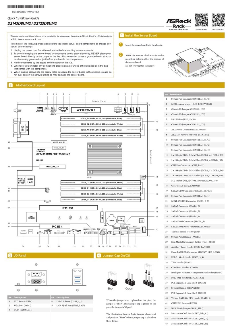
No. Description No. Description
1 UID Switch (UID1) 4 10G LAN RJ-45 Port (LAN1)
2 USB 3.2 Gen1 Ports (USB3_1_2) 5 10G LAN RJ-45 Port (LAN2)
3 LAN RJ-45 Port (IPMI_LAN1) 6 VGA Port (VGA1)
I/O Panel3
3
6
2
1 4
5
26.7 cm (10.5 in)
26.4 cm (10.4 in)
UID1
T:USB3_2
B:USB3_1
CPU1_HSBP1
PECI1
DDR5_A1
DDR5_B1
DDR5_C1
DDR5_D1
IPMI_LAN1
USB 3.2
Gen1 Ports
LAN1 LAN2
VGA1
ASPEED
AST2600
SPC741D8UD-2T:
Intel
X710-AT2
CPU0
DDR5_H1
DDR5_G1
DDR5_F1
DDR5_E1
PCIE7
PCIE6
PCIE5
PCIE4
BMC
ROM
COM1
BMC_SMB_1 IPMB_1
SUPER
I/O
ME_RECOVERY1
Dr. Debug
BIOS
ROM
TPM_BIOS_PH1 RAID_1
AUX_PANEL1
NMI_BTN1
PASSWORD_CLEAR1
CLRMOS1
SPEAKER1
TR1PANEL1
MSAS_HD0_7
M2_1
M2_1
BAT1
SATAPWR1
FAN1
FAN2
FAN3
FAN4
FAN5
FAN6
ATX12V1
ATX12V2
ATX12V3
MCIO1
MCIO2
PSU_SMB1
ATX4PIN1
PWM_CFG1
SPC741D8UD-2T
SPC741D8UD-2T/X550
MINISAS_1MINISAS_2
SPC741D8UD-2T/X550:
Intel
X550-AT2
USB1_2
SPC741D8UD-2T/X550 only:
1
6
7
5
9
10
15
13
14
16
11
12
17
18
19
20
2 3 4
8
21
22
23
24
25
26
27
2930313233343536
37
38
40
43
41
42
44
45
28
BMC_SMB_2
39
SPC741D8UD-2T/X550 only:
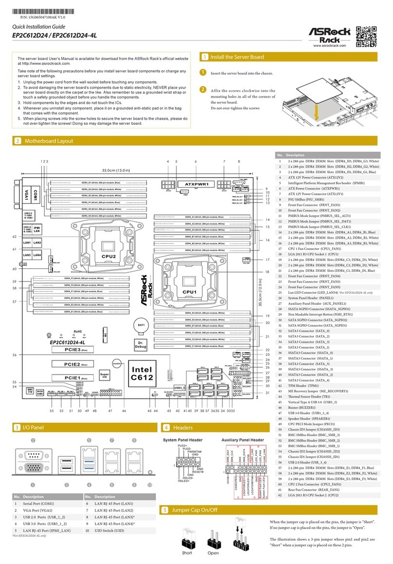
No. Description
1Backplane PCI Express Hot-Plug Con-
nector (CPU1_HSBP1)
2 CPU PECI Mode Jumper (PECI1)
32 x 288-pin DDR5 DIMM Slots
(DDR5_A1, DDR5_C1)
42 x 288-pin DDR5 DIMM Slots
(DDR5_B1, DDR5_D1)
5 PSU SMBus Header (PSU_SMB1)
6Micro-Fit ATX 4Pin Power Connector
(ATX4PIN1)
7Mini Cool Edge IO x8 Connector
(MCIO1)
8Mini Cool Edge IO x8 Connector
(MCIO2)
9PWM Conguration Header
(PWM_CFG1)
10 LGA 4677 CPU Socket (CPU0)
11 ATX 12V Power Connector (ATX12V1)
12 ATX 12V Power Connector (ATX12V2)
13 ATX 12V Power Connector (ATX12V3)
14 2 x 288-pin DDR5 DIMM Slots
(DDR5_E1, DDR5_G1)
15 2 x 288-pin DDR5 DIMM Slots
(DDR5_F1, DDR5_H1)
16 Micro-Fit SATA Power Connector
(SATAPWR1)
17 Clear CMOS Pad (CLRMOS1)
18 System Fan Connector (FAN1)
19 System Fan Connector (FAN2)
20 System Fan Connector (FAN3)
21 System Fan Connector (FAN4)
22 System Fan Connector (FAN5)
23 System Fan Connector (FAN6)
24 MiniSAS HD SATA/PCIE Selection
Jumper (MINISAS_2)
25 MiniSAS HD SATA/PCIE Selection
Jumper (MINISAS_1)
26 MiniSAS HD Connector (MSAS_HD0_7)
27 Speaker Header (SPEAKER1)
28 USB 2.0 Header (USB1_2)
(SPC741D8UD-2T/X550 only)
29 System Panel Header (PANEL1)
30 Auxiliary Panel Header (AUX_PANEL1)
31 Non Maskable Interrupt Button
(NMI_BTN1)
32 ermal Sensor Header (TR1)
33 Password Reset Jumper
(PASSWORD_CLEAR1)
34 Virtual RAID On CPU Header (RAID_1)
35 SPI TPM Header (TPM_BIOS_PH1)
36 M-key M.2 Socket (M2_1) (Type 2280)
37 ME Recovery Jumper
(ME_RECOVERY1)
38 Intelligent Platform Management Bus
Header (IPMB_1)
39 BMC SMBus Header (BMC_SMB_2)
(SPC741D8UD-2T/X550 only)
40 BMC SMBus Header (BMC_SMB_1)
41 Serial Port Header (COM1)
42 PCI Express 5.0 x16 Slot (PCIE4)
43 PCI Express 5.0 x16 Slot (PCIE5)
44 PCI Express 5.0 x16 Slot (PCIE6)
45 PCI Express 5.0 x16 Slot (PCIE7)
SPC741D8UD-2T | SPC741D8UD-2T/X550
Quick Installation Guide
www.asrockrack.com SPC741D8UD-2T SPC741D8UD-2T/X550
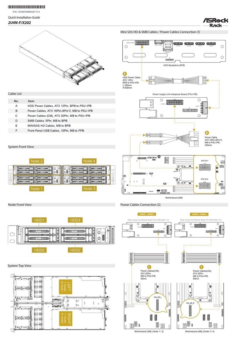
We recommend using the CPU Installation tool to avoid CPU pin-bent problem.
5
Remove the CPU socket cover and open
the socket lever.
Align and install the processor on the
carrier and make sure the arrow is located
in the correct direction. Close the socket
lever.
Carefully ip the carrier assembly. Apply
a thermal paste.
Install the heatsink to the CPU carrier.
en install the heatsink and CPU carrier
to the socket.
Install the Processor and Heatsink
1
2
CPU Carrier
Socket Dust Cover
3
4
6
5
180o
7
CPU Carrier
8
Socket
CPU Carrier
Heatsink
Tighten the corner fasteners. Secure
the heastink to the motherboard with a
screwdriver.
9Install the Memory
7Install the PCIE Card
1Remove the bracket facing the slot that
you intend to use. Keep the screw for later
use.
2Align the card connector with the slot and
press rmly until the card is completely
seated on the slot.
Fasten the card to the chassis with the
screw.
3
6LAN Port LED Indications
IPMI LAN Port
ACT/LINK LED
SPEED LED
LAN Port
Activity / Link LED Speed LED
Status Description Status Description
O No Link O 10Mbps connection or no
link
Blinking Yellow Data Activity Yel low 100Mbps connection
On Link Green 1Gbps connection
10G LAN Port
Activity / Link LED Speed LED
Status Description Status Description
O No Link O 100Mbps connection or no
link
Blinking Yellow Data Activity Orange 1Gbps connection
On Link Green 10Gbps connection
ACT/LINK LED
SPEED LED
LAN Port
9
10
8M.2 SSD Module Installation
1
2
3
Prepare a M.2 SSD module and the screw.
Gently insert the M.2 SSD module into the M.2
slot. Please be aware that the M.2 SSD module only
ts in one orientation.
Tighten the screw with a screwdriver to secure the
module into place. Please do not overtighten the
screw as this might damage the module.
20o
NUT1NUT2
System Panel Auxiliary Panel
11 Headers
GND
RESET#
PWRBTN#
PLED-
PLED+
GND
HDLED-
HDLED+
1
GND
GND
BMC_SMBCLK1
BMC_Alert1_N
CASEOPEN#
1
SMB_SMBDATA1
+3VSB
P0_LED_0
LAN1_LINK_P
P1_LED_0
LAN2_LINK_P
+5VSB
GND
GND
LOCATORLED+
LOCATORLED-
LOCATORBTN#
System_Fault_LED_P
System_Fault_LED_N
AB
CD
E
SPI TPM Header
SPI_WP
SPI_CS
MISO
RSMRST#
TPM_CS#
SPI PIRQ
SPI_RST
MOSI
SPI_CLK
+3.3V
GND
SPI_HOLD
X
1
10 Install the Power Cables
ATX12V
4
8
1
5
12V
GND
ATX4PIN1
SATAPWR1
Micro-Fit Power Connector
1
N/A
GND
GND
+12V
GND
+12V
+5V
N/A
24pin-to-4pin
Converter Cable
12
34
ATX_PWROK
PSON#
GND
ATX_+5VSB
123
Unlock a DIMM slot by
pressing the module clips
outward.
Insert the memory module. Lock the clips.

This manual suits for next models

1

Other ASROCK Rack Computer Hardware manuals

ASROCK Rack EP2C622D16FM User manual

ASROCK Rack

ASROCK Rack EP2C622D16FM User manual

ASROCK Rack EPC621D8A User manual

ASROCK Rack

ASROCK Rack EPC621D8A User manual

ASROCK Rack 1U12XL C622 RPSU User manual

ASROCK Rack

ASROCK Rack 1U12XL C622 RPSU User manual

ASROCK Rack EP2C612D24 User manual

ASROCK Rack

ASROCK Rack EP2C612D24 User manual

ASROCK Rack 2U4N-F/X202 User manual

ASROCK Rack

ASROCK Rack 2U4N-F/X202 User manual

ASROCK Rack D2143D8UM2 User manual

ASROCK Rack

ASROCK Rack D2143D8UM2 User manual

ASROCK Rack EP2C621D12 WS User manual

ASROCK Rack

ASROCK Rack EP2C621D12 WS User manual

ASROCK Rack 1U4G-ROME User manual

ASROCK Rack

ASROCK Rack 1U4G-ROME User manual

ASROCK Rack MP-1543R4 User manual

ASROCK Rack

ASROCK Rack MP-1543R4 User manual

ASROCK Rack C3758D4I-4L User manual

ASROCK Rack

ASROCK Rack C3758D4I-4L User manual

Popular Computer Hardware manuals by other brands

Nvidia ConnectX-7 user manual

Nvidia

Nvidia ConnectX-7 user manual

Xycom XVME-655 manual

Xycom

Xycom XVME-655 manual

IEI Technology IOWA-GX user manual

IEI Technology

IEI Technology IOWA-GX user manual

EVGA 141-BL-E759 user manual

EVGA

EVGA 141-BL-E759 user manual

Freescale Semiconductor MC9S08PT60 Reference manual

Freescale Semiconductor

Freescale Semiconductor MC9S08PT60 Reference manual

Acrosser Technology ACM-XE21B6 user manual

Acrosser Technology

Acrosser Technology ACM-XE21B6 user manual

BCM RX945GC user manual

BCM

BCM RX945GC user manual

Enclustra Mercury KX1 user manual

Enclustra

Enclustra Mercury KX1 user manual

SilverStone SST-FP36 quick start guide

SilverStone

SilverStone SST-FP36 quick start guide

Lexicon VORTEX - MANUAL 2 user guide

Lexicon

Lexicon VORTEX - MANUAL 2 user guide

AmbiCom WL54-CF user manual

AmbiCom

AmbiCom WL54-CF user manual

Inova GigaPACK user manual

Inova

Inova GigaPACK user manual

Renesas Converter Board PCA7752AG02 user manual

Renesas

Renesas Converter Board PCA7752AG02 user manual

Renesas M32170T-PTC user manual

Renesas

Renesas M32170T-PTC user manual

QNAP TS-855eU user manual

QNAP

QNAP TS-855eU user manual

Pico Macom C860 Specifications

Pico Macom

Pico Macom C860 Specifications

TDK HHM Series HHM2411 Specification sheet

TDK

TDK HHM Series HHM2411 Specification sheet

Raidon SAFETank Series user manual

Raidon

Raidon SAFETank Series user manual

manuals.online logo
manuals.online logoBrands
  • About & Mission
  • Contact us
  • Privacy Policy
  • Terms and Conditions

Copyright 2025 Manuals.Online. All Rights Reserved.