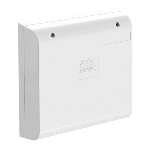
Assa Abloy Medeco XT AIM Operation manual


®
2
1.
2.

3
Table of Contents
Getting Started
Introduction –Medeco XT Access Interface Module (AIM) ......................................................................................... 4
About Your Product Box –QR Codes................................................................................................................................... 4
XT AIM Description.................................................................................................................................................................... 5
Using Your XT AIM
Relay and Power Terminals..................................................................................................................................................... 7
Nine Position I/O Terminal...................................................................................................................................................... 7
Five Position External Power Terminal................................................................................................................................ 8
XT AIM Controller Modes......................................................................................................................................................11
Standard Mode, Key Power...................................................................................................................................................11
Standard Mode, External Power..........................................................................................................................................12
Toggle Mode..............................................................................................................................................................................13
Time Delay Mode .....................................................................................................................................................................15
Dual User Authentication Mode .........................................................................................................................................16
Configuring Your XT AIM
Setting the Functional Mode Selection ............................................................................................................................19
Installing Your XT AIM
Before You Begin......................................................................................................................................................................21
What Is Included In the Box? ...............................................................................................................................................23
What Tools are Required/Needed?....................................................................................................................................24
Installation –Mounting the XT AIM Reader.....................................................................................................................25
Installation –Mounting & Connecting the XT AIM Controller ..................................................................................28
Contacting Medeco
Contact Medeco Technical Support ..................................................................................................................................30

4
Getting Started
Introduction –Medeco XT Access Interface Module (AIM)
This guide contains installation instructions, usage & feature information, explanation of functional modes, and
settings for your Medeco XT Access Interface Module (AIM).
This guide is available for print, download and online use on the Medeco XT Access Interface Module (AIM)
product page. The Medeco XT AIM product page can be found at the following web address:
https://www.medeco.com/en/site/medeco/technology/ecylinder/medeco-xt1/medeco-xtaim/
The Medeco XT Web Manager documentation is available from the Help link found in the XT Web Manager
Software. The Medeco XT Web Manager documentation provides instructions for overall system use, including
programming and scheduling of your XT keys, accessing audit information, and data analytics. Additionally, XT
key information and tips, including maintenance and usage, can be found here, or you may visit the following
web address:
https://www.medeco.com/en/site/medeco/technology/ecylinder/medeco-xt1/medeco-xt/medeco-xtkeytips/
This guide assumes that you are familiar with installing typical locking and security device systems. You should
pay special attention to the shaded text used throughout this guide.
Information Warnings Tips
These symbols emphasize important information critical to the successful installation of your XT AIM.
About Your Product Box –QR Codes
Your Medeco XT AIM product boxes contains the XT AIM Controller and the XT AIM Reader, packaged
separately. The XT AIM product box includes two QR codes for convenient access to the XT AIM Installation &

5
User Guide or the Medeco Technical Support chat line. When you scan the XT AIM Installation & User Guide QR
code with your mobile device, you may be prompted to allow your device to navigate to a web address or allow the
guide to download to your device prior to it being displayed. After you scan the Technical Support chat line QR code,
you will be prompted to enter your name on the Technical Support chat page to initiate contact.
Medeco Technical Support Chat Line QR code
XT AIM Description
The Medeco XT AIM (Access Interface Module) extends the capabilities of the Medeco XT System to interact with a
variety of access control devices often found around the periphery of a door opening such as electric strikes,magnetic
locks, alarms, cameras, lights, etc. As illustrated in Figure 1, the Medeco XT AIM consists of a Reader and an
Intelligent Controller assembly. The Reader is mounted in an accessible location while the Controller is located
in a secure location. The Reader and XT AIM Reader cable function as a communication bridge for the XT key and
the Intelligent Controller to exchange data. The Controller contains circuitry and output switches that when
authorized by an XT key can enable or disable connected devices.
More information on the XT key can be found on the Medeco website XT Key Tips page.
https://www.medeco.com/en/site/medeco/technology/ecylinder/medeco-xt1/medeco-xt/medeco-xtkeytips/
For an XT AIM Controller configured to any mode, the Control Key type provides a special and unique function.
The Control Key type in XT Web Manager is used to retrieve cylinder audits and as a tool to easily replace a
cylinder core. An XT key that is both authorized for an XT Lock and programmed as a Control Key type, will open
the XT Lock, but the relays will not be activated and the audit record event will be recorded as a Core Change
event. You should set your XT Key type to Operator or Operator+Audit for use with the XT AIM.
Information on using the Control Key Type
For a Medeco XT AIM Controller configured to any mode, using an authorized XT Key set to the
Control key type will not activate the relays and will record the audit event type as a Core
Change event. The Control Key type should not be used for XT keys assigned to key holders
who only use an XT Key for access. The Operator and Operator+Audit key type should be used
instead.

6

7
Using Your XT AIM
Relay and Power Terminals
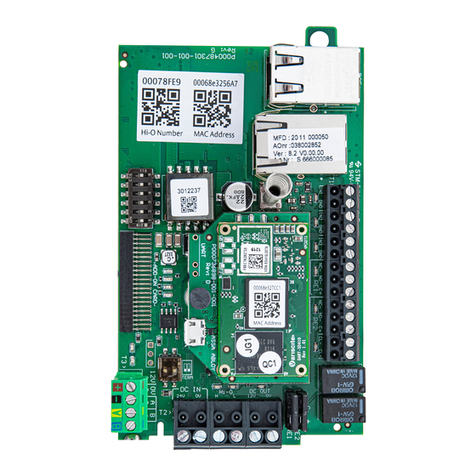
On the side of the XT AIM Controller are the 9 Position Input/output (I/O) and 5 Position External Power
Terminals used to connect external devices and to provide auxiliary power.
The 9 Position I/O Terminal consists of the input and output terminals for the 4 relays. The 5 Position Power
Terminal provides the fused and non-fused external power source connection points. An AC or DC power supply
up to 24V can be connected to the Controller. The number of available I/O terminals allows for a wide range of
possible configurations for custom applications.
The XT AIM Controller contains a high power electro-mechanical relay and two low power digital relays that
provide safe and fully isolated control of external power sources. A control input is also provided for external
override of the relays. The following summarizes the type and function of the various XT AIM Controller relays.
Nine Position I/O Terminal
Electro-Mechanical Relay, Position (POS) 1/2/3
The electro-mechanical relay is single-pole-double-throw (SPDT) with both Normally Open (RLY NO) and
Normally Closed (RLY NC) contacts to a Common Contact (RLY COM). In the inactive state, the normally open
terminal (POS 1) is open and the common terminal (POS 2) is connected to the normally closed terminal (POS
3). When the relay is activated the common terminal (POS 2) is switched to the opposite state.
The electro-mechanical relay contacts are rated at 250V and up to 2 amps. The DC load breaking capacity of the
mechanical relay is 60 watts, i.e. 30 volts at 2amps. For inductive loads, an external appropriately sized snubber
diode must be installed across the load.
Digital Relays, POS 4/5 and POS 6/7

8
The two digital solid-state relays are single-pole-single-throw (SPST) normally open contacts. One solid-state
relay DIGITAL SW/DIGITAL COM, (POS 4/5) is activated during authorized key access events and the other relay
UNAUTH SW/UNAUTH COM, (POS 6/7) is activated during unauthorized events. The digital relays can switch up
to 24V AC or DC at 100 mA.
AUX Relays, POS 8/9
The AUX+ and AUX- inputs for the AUX function provide an external override for deactivating the relays. When
3V or greater is applied across AUX+ and AUX-, the mechanical and digital relays de-energize immediately. If
the AUX function is not used, POS 8/9 should be shorted together.
Five Position External Power Terminal
The XT AIM can be powered via an external AC or DC power sources. The DC input voltage range is between 7V
and 24V. The AC input voltage range is between 18 and 24Vrms. The XT AIM input current requirement is 30mA
maximum.
AC/DC24V/IN POS 1/RTN
The 5 position external power terminal is used for connecting an external power supply to the XT AIM
Controller. If used, external power is connected between the AC/DC 24V IN terminal and any of the RTN
terminals. The XT AIM is protected by an overvoltage protection circuit which is triggered when current greater
than 2 amps is drawn. If the overvoltage protection circuit is triggered, the circuit remains open until the current
drops to 2 amps or below, at which time the circuit closes and the XT AIM resumes normal operation.
Information on the AUX Terminals
If the AUX function is not used, POS 8 & 9 terminals should be shorted together.

9
AC/DC FUSED POS 2/RTN
Power to control external devices must be provided. The AC/DC FUSED terminal may be used for this purpose.
The voltage applied to AC/DC 24V IN is made available at the AC/DC FUSED terminal through a resettable fuse
(PTC). The PTC fuse trip rating is 2 amps.
Information on the Overvoltage Protection Circuit
Connecting a voltage greater than 24V to the AC/DC 24VIN terminal will trigger the overvoltage
protection circuit. When the XT AIM detects current greater than 2 amps, the circuit is
triggered. When current drops to 2 amps or less, the circuit is closed.
Warning –Connecting External Power to XT AIM Reader
DO NOT Apply voltages above 60V as this may damage the Controller and may render the XT
AIM inoperable.

10
9 Position Terminals
Terminal
Number
Terminal Name
Terminal Function
1
RLY NO
Relay Normally Open (NO)
2
RLY COM
Relay Common Contact
3
RLY NC
Relay Normally Closed (NC) contact
4
DIGITAL SW
Authorized solid-state relay
common
5
DIGITAL COM
Authorized solid-state Relay switch,
normally open (NO)
6
UNAUTH SW
Unauthorized solid-state Relay
common
7
UNAUTH COM
Unauthorized solid-state Relay
switch, normally open (NO)
8
AUX+
AUX inputs
9
AUX-
5 Position Terminals
1
AC/DC 24V IN
External power input (7-24V DC; 18-
24VRMS AC)
2
AC/DC Fused
External power out (Fused at 2
amps)
3
RTN
External power return (all returns
are internally connected)
4
RTN
External power return
5
RTN
External power return

11
XT AIM Controller Modes
Your XT AIM can be configured to function in one of the following five (5) primary modes;
Standard Mode, Key Power Mode
Standard Mode, External Power Supplied
Toggle Mode
Time Delay Mode
Dual User Authentication Mode
When the XT AIM Controller is shipped from the Medeco factory, the Controller is set to Standard, Key Power
mode. Prior to installation, ensure that the XT AIM Controller is configured to the functional mode desired. The
functional mode is set using the four DIP switches located back side of the Controller.
Information on the functional modes is described below and the corresponding DIP switch settings are shown
on the DIP switch settings table in the Setting the Functional Mode section of this document.
Standard Mode, Key Power
In the Standard Mode with Key Power Only, the XT key provides the only source of power to the XT AIM Reader
and Controller. In this mode, the mechanical relay remains activated as long as the key is securely inserted into
the key port, up to the Cylinder Unlock Time setting. The cylinder unlock time can be configured in the Medeco
XT Web Manager Software. The digital relay remains activated as long as the key is securely inserted into the
key port, up to 2 seconds. If the key breaks insertion contact anytime within the unlock time setting, then the
relays deactivate. The maximum time that the digital contact will remain activated is 2 seconds.
Warning –XT Web Manager Key Types
The Control Key type should not be used for XT keys assigned to daily users or key holders who only
use an XT Key for access. The Operator and Operator+Audit key type should be used instead. Your XT
AIM Controller will not perform as intended if an authorized XT Key set to the Control Key type is used.

12
When your XT AIM Controller is operating in Key Power mode, the XT AIM Reader LED Indicator will remain unlit
until an authorized XT key is inserted into the key port. If the XT key is authorized, the XT AIM Reader will display
a solid green light.
In order to enable this mode, you should refer to the DIP switch settings table in the Setting the Functional
Mode section of this document.
Standard Mode, External Power
With the XT AIM Controller configured in the Standard Mode with External Power, three operational
configurations can be defined. Upon insertion of an authorized XT key, the mechanical relays can be defined to
latch for the following durations:
Cylinder Unlock Time
For 30 Second Latch
For 60 Second Latch
When an authorized XT key is inserted into the Reader, the mechanical and digital relays will immediately
activate. In regard to the mechanical relays, the latch duration can be configured to hold for the Cylinder Unlock
UNAUTH Relay, Additional Information
Any time an XT key is inserted into the Reader and the key fails to authenticate, the UNAUTH
relay will close.
Information on using the XT AIM without a connected power supply
If you do not have a connected external power supply, Key Power mode is the default mode.
This is the only functional mode operational without external power.

13
Time or for either 30 seconds or 60 seconds. For the Digital relays, the latch duration for all noted operational
modes is approximately 2 seconds. The DIP switch settings table provides the specific DIP switch settings
necessary to configure your XT AIM Controller to Cylinder Unlock Time, 30 second hold, or 60 second hold in
Standard Mode.
When your XT AIM Controller is configured to any of the three available operational configurations in this mode,
the XT AIM Reader displays a solid green light. When an authorized XT key is inserted into the key port, the XT
AIM Reader will display a brief green flash. The XT key displays a green light when authorized and captures the
event, storing it locally as an audit record. More information on the XT key LED indicators can be found in the
Medeco XT Web Manager User Guide that is available from the Help link in the Medeco XT Web Manager
Software.
Toggle Mode
In order to use Toggle mode external power must be connected to the XT AIM Controller. In Toggle Mode, two
operational configurations are available.
UNAUTH Relay, Additional Information
Any time an XT key is inserted into the Reader and the key fails to authenticate, the UNAUTH
relay will close.
Information on power loss in Standard Mode with External Power
Standard mode with External Power will default to Standard Mode with Key Power in the case
that external power to the XT AIM Controller is lost. Connected external devices may not
operate as intended.
Cylinder Unlock Time
The Cylinder Unlock Time is a setting within the Medeco XT Web Manager Software that refers
to the maximum duration that the Controller is powered by the XT key. The time can be
incrementally adjusted from .8 seconds to 12 seconds. The Cylinder Unlock Time begins when
the key is inserted into the Reader. The key must maintain insertion contact during the entire
Cylinder Unlock Time period.

14
Single Authentication
Dual Authentication
Toggle mode allows the XT key to act as a toggle switch by changing the state of the mechanical relay, RLY NO
and RLY NC each time an authorized XT key is inserted into the XT AIM Reader. The digital relays will activate
for 2 seconds each time the mechanical relay changes state.
Single Authentication
In single authentication, an authorized XT key is used to activate and deactivate the relays. In this mode, the
mechanical relay is activated when you insert your authorized XT key and the relay remains in this state until
the next time an authorized XT key is inserted. The digital switch is activated when your XT key is authenticated
and when the mechanical relay changes states.
Dual Authentication
For dual authentication, two authorized XT key insertions are required for the relay to change state. Any
authorized XT key can be used for either the first or second XT key insertions. When the authorized XT key is
inserted for the second time, the mechanical relay is activated and remains in this state until the next time
authorized XT key insertions are sequentially completed. The digital switch is activated each time the
mechanical relay changes state at the second authorized XT key insertion.
With external power being supplied, the XT AIM Reader will display a solid green light indicating the presence
of power. When an authorized XT AIM key is inserted into the XT AIM Reader, the light will briefly flash and the
XT key will display a green light. In Toggle mode configured for dual authentication, the XT AIM Reader displays
a flashing green light after the first XT key is inserted and authenticated to indicate that the XT AIM system is
Information on power loss in Toggle mode
In the case of power loss, Toggle mode will operate as Standard Mode with Key Power,
however connected external devices may not operate as intended.
A Note on the AUX Relay
The AUX input can be used as an emergency toggle override to deactivate the mechanical relays
without creating an audit record.

15
ready for a 2nd authorized XT key to be inserted. The second key must be inserted within 60 seconds. If the
second key is not inserted within 60 seconds, the dual authentication cycle expires with no change in the state
of the relays.
The DIP switch setting table in the Setting the Functional Mode section of this document provides the switch
settings necessary to use your XT AIM Controller in single or dual authentication Toggle mode.
Time Delay Mode
When the XT AIM Controller is configured for Time Delay Mode, four operational modes are available. A
connected external power supply is necessary to use your XT AIM in any of the Time Delay operational modes.
All Time Delay operation modes require two insertions of the same authorized XT key.
1 Minute Time Delay
2 Minute Time Delay
3 Minute Time Delay
5 Minute Time Delay
Your XT AIM Controller can be configured to a 1-minute, 2-minute, 3-minute, or 5-minute time delay. Time
Delay mode requires one authorized XT key to be inserted twice into the XT AIM Reader. When the authorized
XT key is initially inserted into the XT AIM Reader, a countdown timer is initiated. At the end of the time delay,
when the second key (must be the same key as the first insertion) is inserted into the XT AIM Reader, the relays
are activated.
The mechanical relay remains activated for 5, 15, 30, or 60 seconds, depending on the configured delay time.
For a 1 minute time delay, the mechanical relay will remain activated for 5 seconds. The 2, 3, & 5 minute time
delay modes will activate the mechanical relay for 15, 30, & 60 seconds, respectively. For all time delay periods,
the digital switch is activated after the second authorized XT key is inserted and remains active for
approximately 2 seconds.
UNAUTH Relay, Additional Information
Any time a key is inserted into the Reader and the keys fails to authenticate, the UNAUTH
relay will close.

16
The table in the Setting the Functional Mode section of this document provides the DIP switch settings for
configuring your XT AIM Controller for use in the 1, 2, 3, or 5 minute Time Delay mode.
Dual User Authentication Mode
With the XT AIM Controller configured in the Dual User Authentication Mode, there are three activation latch
times for the mechanical relays to choose, each requiring dual user authentication to activate. The digital relays
activate for 2 seconds for any mode selected. The three operational configurations for Dual User Authentication
require external power to be supplied to the XT AIM Controller.
Dual User Authentication, Mechanical Relay Latch, Cylinder Unlock Time
Dual User Authentication, Mechanical Relay Latch, 30 Seconds
Dual User Authentication, Mechanical Relay Latch, 60 Seconds
In Dual Authentication mode, two different authorized XT keys are required. Each XT key must be inserted in
sequence to activate the XT AIM Controller relays.
You can configure the XT AIM Controller to activate the relays when the second authorized XT key is inserted
and to remain activated for the duration of the Cylinder Unlock Time Setting as configured in the Medeco XT
Web Manager Software. If the key breaks insertion contact anytime within the unlock time setting, then the
mechanical and digital relays deactivate.
UNAUTH Relay, Additional Information
Any time a key is inserted into the Reader and the keys fails to authenticate, the UNAUTH
relay will close.
Information on power loss in Time Delay Mode
In the event of power loss, the XT AIM Controller will operate in Standard Mode with Key
Power. Connected external devices may not operate as intended.

17
When configured to a 30 second or 60 second hold, the mechanical relay remains activated for a period of 30
or 60 seconds, respectively, after the 2nd XT key is inserted and authenticated. The Digital relays also activate
when the second XT key is inserted and authenticated and with remain activated for 2 seconds.
The Functional Mode DIP switch settings table in the following section provides the DIP switch settings
necessary to configure your XT AIM Controller for use in one of the three Dual Authentication modes.
When your XT AIM Controller is configured to one of the three Dual Authentication operational mode options,
the XT AIM Reader displays a continuous solid green light to indicate external power is being supplied. When
an authorized XT key is inserted into the key port, the XT AIM Reader will display a brief green flash and the XT
key will display a green light. After the first authorized XT key is removed, the XT AIM Reader quickly flashes a
green light for sixty seconds to indicate that it is ready for a second authorized XT key to be inserted. If the
second authorized XT key is not inserted within 1 minute after removing the first XT key, the first XT key must
be reinserted to initiate the process again.
Cylinder Unlock Time
The Cylinder Unlock Time is a setting within the Medeco XT Web Manager Software that refers
to the maximum duration that the Controller is powered by the key. The time can be
incrementally adjusted from .8 seconds to 12 seconds. The Cylinder Unlock Time begins when
the key is inserted into the Reader. The key must maintain insertion contact during the entire
Cylinder Unlock Time period.
UNAUTH Relay, Additional Information
Any time a key is inserted into the Reader and the keys fails to authenticate, the UNAUTH relay
will close.

18
Information on power loss in Dual User Authentication Mode
Dual User Authentication Mode will operate in Standard Mode with Key Power if external
power to the XT AIM Controller is lost. Connected external devices may not operate as
intended.

19
Configuring Your XT AIM
Setting the Functional Mode Selection
Prior to installation, you should configure the XT AIM Controller by locating the four DIP switches located
adjacent to the XT AIM Reader cable inputs on the side of the unit.
The following table shows the available modes of operation and their corresponding DIP switch settings.
Sliding a switch upward places it in the ON position.

20
Table of contents
Other Assa Abloy Control Unit manuals

Assa Abloy
Assa Abloy Securitron NL4 User manual

Assa Abloy
Assa Abloy EffEff 1340-20 User manual

Assa Abloy
Assa Abloy EffEff 1338-14 User manual

Assa Abloy
Assa Abloy TRAKA UD0011 User manual

Assa Abloy
Assa Abloy OneSystem N5952 User manual

Assa Abloy
Assa Abloy OneSystem Service Module User manual

Assa Abloy
Assa Abloy LCU9101 User manual

Assa Abloy
Assa Abloy Effeff ePED 1386CMC User manual

Assa Abloy
Assa Abloy HES iCLASS IC0020 Owner's manual
Assa Abloy
Assa Abloy Incedo InControl 3270 User manual