Assa Abloy effeff 720-40 Quick start guide

DE Seite 2
EN Page 20
FR Page 40
IT Pagina 60
NL Pagina 60
Experience a safer
and more open world
assaabloyopeningsolutions.de
Connecting diagrams
D0060202
Escape door control unit type 720-40
Escape route technology
B V -
A V+
RR
RR GND
AKRR
AKRR V+
GND
+
1332-1x
7 Sabotage C
9 Sabotage NC
13 Taster R
14 Taster R GND
10 Taster L
11 Taster L GND
17 Summer
–
16 Summer +
4 LED ge +
1 LED ge
–
3 LED gn –
2 LED rt –
5 LED rt +
6 LED gn +
1380E03
9 Tamper
10 Tamper
11 Push button R
12
Push button R GND
13 Push button L
14
Push button L GND
8 Buzzer
–
7 Buzzer +
2 LED ye +
1 LED ye
–
3 LED gn –
5 LED rd –
4 LED gn +
6 LED rd +
1332-1x
7 Sabotage C
9 Sabotage NC
13 Taster R
14 Taster R GND
10 Taster L
11 Taster L GND
17 Summer
–
16 Summer +
4 LED ge +
1 LED ge
–
3 LED gn –
2 LED rt –
5 LED rt +
6 LED gn +
9 Tamper
10 Tamper
11 Push button R
12
Push button R GND
13 Push button L
14
Push button L GND
8 Buzzer
–
7 Buzzer +
2 LED ye +
1 LED ye
–
3 LED gn –
5 LED rd –
4 LED gn +
6 LED rd +
720-40
38V –
27
Ü NA
37
30
ye
29
gn
28
rd
22V+
32H–
31
H+
26
Tamper
25
23
24
42 +24 V
41 0 V
1E4
2 E4 GND
8 TS GND
9 TS Data
36
RR
35GND
34AKRR
33
V+
F
E
D
C
B
A
(B)
(A)
V+
Push button R
GND
Push button L
TS-Bus
+24 V
0 V
1380E10
8 Buzzer
–
9 LED (+24V)
3
Emergency open 4
1
Emergency open 2
JP1
1
3
2
+24 V
0 V
1380E03
JP1
1
3
2
JP1
1
3
2
720-32-SRM
0 V
+24 V
max. 19
720-40
8 -
7 +
6
2
5
1
40 -Vb
39 +Vb
Possible profile
Emergency release
i.g. BMA
If not connected:
install bridge
Connecting the respective
Locking element
See instructions D00470xx
Br2
Br1
12
12
Centr. NA
F door monitoring
E door monitoring
D Lock
C Lock
12
1
12
2
2
12
12
1
12
Push b
P
P
P
P
P
utt
o
n R GN
D
13
13
13
13
Push bPush b
Push b
Push
uttonutton
L
L
L
L
14
Push b
b
utton
utton
LGN
L GND
L GND
GND
GND
L GND
LGN
GN
GN
L GNDL GND
12
Push butt
o
n R GND
13
3
13
1
1
3
Push butt
o
n
L
14
4
Push b
Pu
utton
tton
L GND
L GND
23
2
4
(
B
)
(A
)
GND
ton
L

2
Eine aktuelle Version dieser Anleitung ist im Internet verfügbar:
https://aa-st.de/file/d00602
Connecting diagrams for the locking elements, please see document D00470xx.
For the connecting diagrams of the door terminals, please refer to the documents supplied with the
devices.
Publisher
ASSA ABLOY Sicherheitstechnik GmbH
Bildstockstrasse 20
72458 Albstadt
GERMANY
Telephone: +49 (0) 7431 / 123-0
Fax: +49 (0) 7431 / 123-240
E-Mail: albstadt@assaabloy.com
Internet: assaabloyopeningsolutions.de
Document number, date
D0060202 01/2021
Copyright
©2021, ASSA ABLOY Sicherheitstechnik GmbH
This document and all its parts are copyrighted. Any use or changes outside the strict limits of the copy-
right are prohibited and liable to prosecution unless prior consent has been obtained from ASSA ABLOY
Sicherheitstechnik GmbH.
This particularly applies to any copying, translations, microforms, or storing and processing in electronic
systems.
Read this manual thoroughly before use and keep it in a safe place for later reference. The manual
contains important information about the product, particularly for the intended use, safety, instal-
lation, use, maintenance and disposal.
Hand the manual over to the user after installation and pass the manual on to the purchaser to-
gether with the product if the product is sold.

3
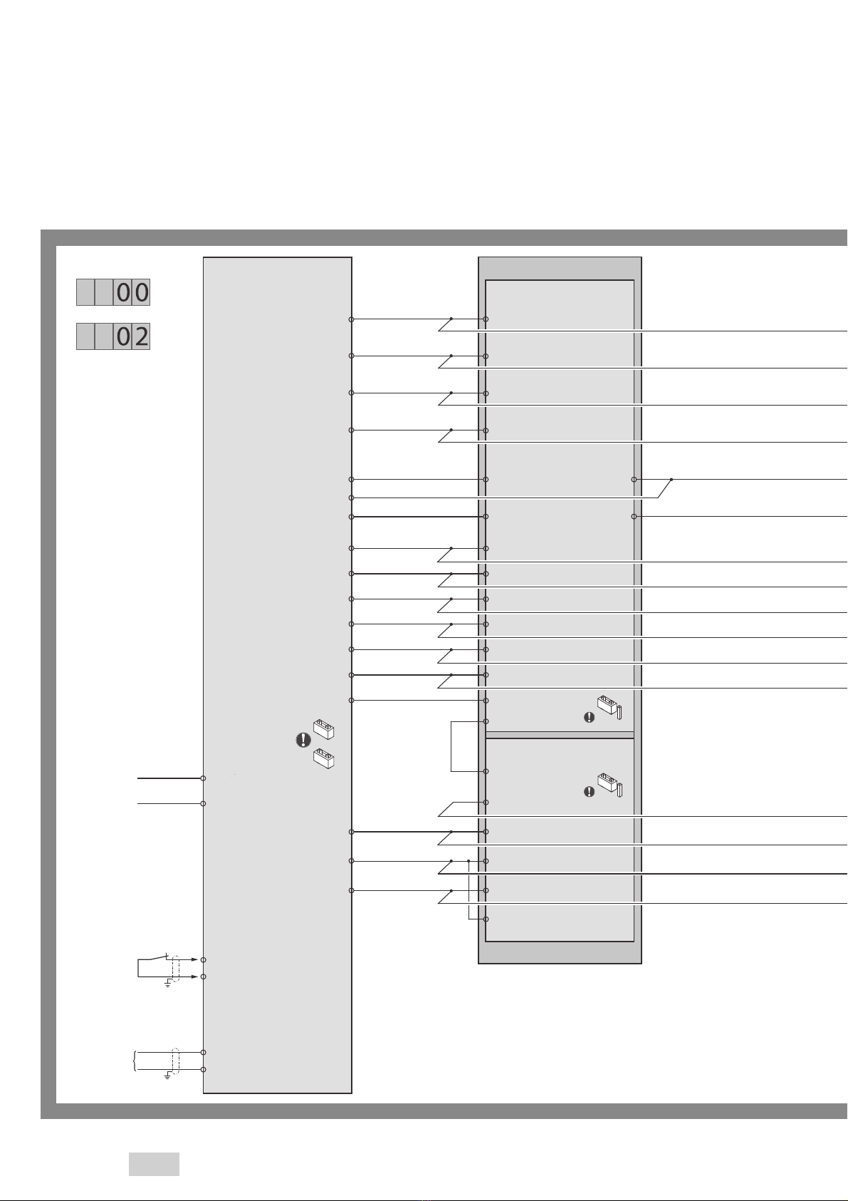
Device overview 720-40 . . . . . . . . . . . . . . . . . . . . . . . . . . . . . . . . . . . . . . . . . . . . . . . . . . . . 5
Terminal assignment. . . . . . . . . . . . . . . . . . . . . . . . . . . . . . . . . . . . . . . . . . . . . . . . . . . . . . . . . . . . . . .5
Connecting diagramms of the operating units . . . . . . . . . . . . . . . . . . . . . . . . . . . . . . . . . . . . . . .6
Connecting diagramms . . . . . . . . . . . . . . . . . . . . . . . . . . . . . . . . . . . . . . . . . . . . . . . . . . . . . 8
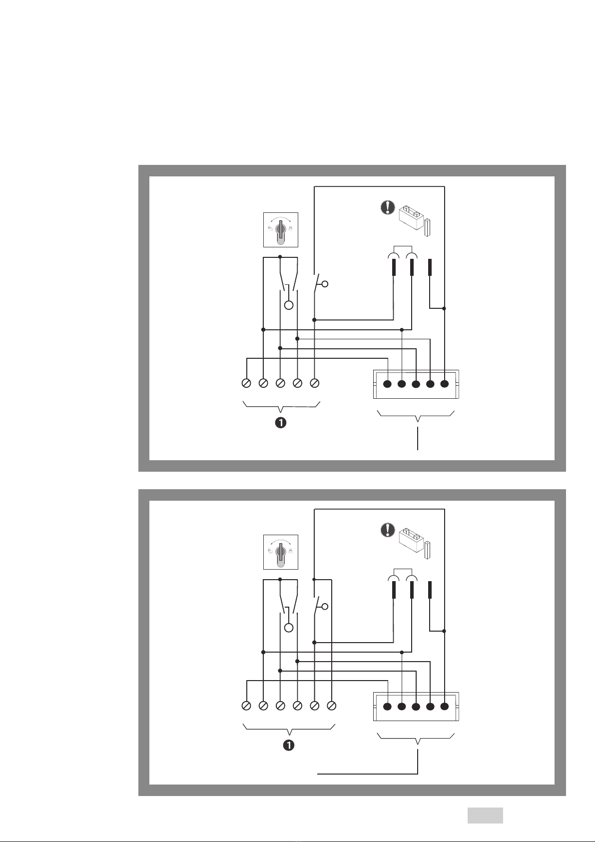
Conventional. . . . . . . . . . . . . . . . . . . . . . . . . . . . . . . . . . . . . . . . . . . . . . . . . . . . . . . . . . . . . . . . . . . . . .8
AP000100: 1380 . . . . . . . . . . . . . . . . . . . . . . . . . . . . . . . . . . . . . . . . . . . . . . . . . . . . . . . . . . . . . . . . . . . . . . . . . . . . . . . . . . . . . 8
AP000200: 1380 with key switch against the direction of escape (inside) . . . . . . . . . . . . . . . . . . . . . . . . . . . .10
AP000300: 1380 with key switch on the outside . . . . . . . . . . . . . . . . . . . . . . . . . . . . . . . . . . . . . . . . . . . . . . . . . . . . . 12
AP000401: 1380-12/-15/-16 . . . . . . . . . . . . . . . . . . . . . . . . . . . . . . . . . . . . . . . . . . . . . . . . . . . . . . . . . . . . . . . . . . . . . . . . 14
AP000501: 1380-15 with key switch against the direction of escape (inside) . . . . . . . . . . . . . . . . . . . . . . . . . 16
AP003100: 1380-12/-16 with key switch against the direction of escape (inside) . . . . . . . . . . . . . . . . . . . . . 18
AP000601: 1380-12/-15/-16 with key switch on the outside . . . . . . . . . . . . . . . . . . . . . . . . . . . . . . . . . . . . . . . . . 20
AP000700: 1337-10/-11. . . . . . . . . . . . . . . . . . . . . . . . . . . . . . . . . . . . . . . . . . . . . . . . . . . . . . . . . . . . . . . . . . . . . . . . . . . . . 22
AP000800: 1337-10/-11 with key switch with on the outside . . . . . . . . . . . . . . . . . . . . . . . . . . . . . . . . . . . . . . . . 24
AP000900: 1370-10. . . . . . . . . . . . . . . . . . . . . . . . . . . . . . . . . . . . . . . . . . . . . . . . . . . . . . . . . . . . . . . . . . . . . . . . . . . . . . . . . 26
AP001000: 1370-10 with key switch on the outside . . . . . . . . . . . . . . . . . . . . . . . . . . . . . . . . . . . . . . . . . . . . . . . . . 28
AP001100: 1337-12. . . . . . . . . . . . . . . . . . . . . . . . . . . . . . . . . . . . . . . . . . . . . . . . . . . . . . . . . . . . . . . . . . . . . . . . . . . . . . . . . 30
AP001200: 1337-12 with key switch against the direction of escape . . . . . . . . . . . . . . . . . . . . . . . . . . . . . . . . . 32
1-contact-operation . . . . . . . . . . . . . . . . . . . . . . . . . . . . . . . . . . . . . . . . . . . . . . . . . . . . . . . . . . . . . 34
AP001300: 1380E10 with operation over access control . . . . . . . . . . . . . . . . . . . . . . . . . . . . . . . . . . . . . . . . . . . . . 34
Bidirectional . . . . . . . . . . . . . . . . . . . . . . . . . . . . . . . . . . . . . . . . . . . . . . . . . . . . . . . . . . . . . . . . . . . . 36
AP001400: 1380 on both sides . . . . . . . . . . . . . . . . . . . . . . . . . . . . . . . . . . . . . . . . . . . . . . . . . . . . . . . . . . . . . . . . . . . . . . 36
AP001500: 1380-15 on both sides. . . . . . . . . . . . . . . . . . . . . . . . . . . . . . . . . . . . . . . . . . . . . . . . . . . . . . . . . . . . . . . . . . . 38
AP003200: 1380-12/-16 on both sides . . . . . . . . . . . . . . . . . . . . . . . . . . . . . . . . . . . . . . . . . . . . . . . . . . . . . . . . . . . . . . 40
AP001600: 1337-10/-11 on both sides . . . . . . . . . . . . . . . . . . . . . . . . . . . . . . . . . . . . . . . . . . . . . . . . . . . . . . . . . . . . . . 42
AP001700: 1370-10 on both sides. . . . . . . . . . . . . . . . . . . . . . . . . . . . . . . . . . . . . . . . . . . . . . . . . . . . . . . . . . . . . . . . . . . 44
AP001800: 1337-12 on both sides. . . . . . . . . . . . . . . . . . . . . . . . . . . . . . . . . . . . . . . . . . . . . . . . . . . . . . . . . . . . . . . . . . . 46
Bidirectional – 1-contact-operation . . . . . . . . . . . . . . . . . . . . . . . . . . . . . . . . . . . . . . . . . . . . . . . 48
AP001900: 1380E10 on both sides with operation over access control . . . . . . . . . . . . . . . . . . . . . . . . . . . . . . . 48
Table of contents

4
Central-Emergency-Open, maximum 19 doors. . . . . . . . . . . . . . . . . . . . . . . . . . . . . . . . . . . . . 50
AP002000: 1380E03 for operation on both sides . . . . . . . . . . . . . . . . . . . . . . . . . . . . . . . . . . . . . . . . . . . . . . . . . . . . 50
AP002100: 1332-10/-11 for operation on both sides. . . . . . . . . . . . . . . . . . . . . . . . . . . . . . . . . . . . . . . . . . . . . . . . . 52
Central-Emergency-Open, maximum 19 doors, with signal function. . . . . . . . . . . . . . . . . 54
AP002200: 1380 with key switch against the direction of escape (inside) . . . . . . . . . . . . . . . . . . . . . . . . . . . .54
AP002300: 1380-15 with key switch against the direction of escape (inside) . . . . . . . . . . . . . . . . . . . . . . . . . 56
AP003300: 1380-12/-16 with key switch against the dircetion of escape (inside) . . . . . . . . . . . . . . . . . . . . . 58
AP002400: 1332-70 with key switch on the outside . . . . . . . . . . . . . . . . . . . . . . . . . . . . . . . . . . . . . . . . . . . . . . . . . 60
AP002500: 1370-10 with key switch on the outside . . . . . . . . . . . . . . . . . . . . . . . . . . . . . . . . . . . . . . . . . . . . . . . . . 62
Central-Emergency-Open, maximum 19 doors, with SW time delay . . . . . . . . . . . . . . . . . 64
AP002600: 1380 with key switch against the direction of escape (inside) . . . . . . . . . . . . . . . . . . . . . . . . . . . .64
AP002700: 1380-15 with key switch against the direction of escape (inside) . . . . . . . . . . . . . . . . . . . . . . . . . 66
AP003400: 1380-12/-16 with key switch against the direction of escape (inside) . . . . . . . . . . . . . . . . . . . . . 68
AP002800: 1332-70 with key switch on the outside . . . . . . . . . . . . . . . . . . . . . . . . . . . . . . . . . . . . . . . . . . . . . . . . . 70
AP002900: 1337-10/-11 with key switch on the outside . . . . . . . . . . . . . . . . . . . . . . . . . . . . . . . . . . . . . . . . . . . . . 72
AP003000: 1370-10 with key switch on the outside . . . . . . . . . . . . . . . . . . . . . . . . . . . . . . . . . . . . . . . . . . . . . . . . . 74

5
Device overview 720-40
Terminal assignment
Fig. 1:
720-40 1
2
3
4
5
6
7
8
9
10
11
12
13
14
15
16
17
18
19
20
21
44
43
42
41
40
39
30
29
28
27
26
25
24
23
22
DIP-button
Menu
buttons
Values
buttons
Menu
display Values
display
ON
1234
1
2
3
4
38 (B)
Locking
(coil) –
37 (A)
Locking
(coil) +
36 (F)
Feedback
Door status
35 (E) GND
34 (D)
Feedback
Locking status
33 (C)
+12 / +24 V out
(maximum 0,4 A)
32 Horn –
31 Horn +
LED yellow
LED green
LED red
Monitoring
Emergency open
Tamper contact
GND
+24 V
CAN-H
CAN-L
+12 / +24 V in
0 V in
Vb – in
Vb + in
E4
E4 GND
E3
E3 GND
E2
E1/E2 GND
E1
TS Bus GND
TS Bus Data
Relais 4 nc
Relais 4 com
Relais 4 no
Relais 3 nc
Relais 3 com
Relais 3 no
Relais 2 nc
Relais 2 com
Relais 2 no
Relais 1 nc
Relais 1 com
Relais 1 no
Button right
Button left
Device overview 720-40

6Device overview 720-40
Fig. 2
1380E10
+–
S2
T
JP
2
3
S
96785 12
11 301611151413
4
2
RRR
1
RD GN YL
Fig. 3:
1380E01
9
JP
1
2
3
S
S2 1
2
10
Tamper
11 12
S2 1
2
13 14
Fig. 4:
1380E03
9
JP
1
2
3
S
S2 1
2S1 1
2
34526781
RD
GN YL
Buzzer
10 11 12 14 13
Connecting diagramms of the operating units

7
Device overview 720-40
Fig. 5:
1385ES1
SYSCON-5
Max.
12 V/100 mA
1
1
2
2
3
3
45
LR
Tamper
JP1
13
2
1385EVL5
Fig. 6:
1385ES2
SYSCON-5
Max.
12 V/100 mA
1
1
2
2
3
3
45
LR
Tamper
JP1
13
2
1385EVL5
6

8Connecting diagramms
AP000100: 1380
720-40
38V –
27
Ü NA
37
30
ye
29
gn
28
rd
22V+
32H–
31H+
26
Tamper
25
23
24
42 +24 V
41 0 V
1E4
2 E4 GND
8 TS GND
9 TS Data
36
RR
35GND
34AKRR
33
V+
F
E
D
C
B
A
(B)
(A)
V+
Push button R
GND
Push button L
9 Tamper
1380
1380E10
1380E01
8 Buzzer
–
11 Push button R
13 Push button L
14
5 Buzzer +
9 LED (+24V)
12 LED ye
11 LED gn
10 LED rd
7 Tamper
6 Tamper
10 Tamper
Possible profile
16
Aux.terminal
3 Emergency open 4
1 Emergency open 2
15
Aux.terminal
14
Aux.terminal
13 Aux.terminal
12
TS-Bus
Emergency release
i.g. BMA
If not connected:
install bridge
+24 V
0 V
Br2
12
Br1
12
Push button R GND
Push button L GND
JP1
1
3
2
JP1
1
3
2
Connecting diagramms
Conventional

9
Connecting diagramms
F door monitoring
E door monitoring
D Lock
C Lock
B V -
A V+
Connecting the respective
Locking element
See instructions D00470xx
RR
RR GND
AKRR
AKRR V+
GND
+

10 Connecting diagramms
AP000200: 1380 with key switch against the direction of escape (inside)
720-40
38V –
27
Ü NA
37
30
ye
29
gn
28
rd
22V+
32H–
31H+
26
25
23
24
42 +24 V
41 0 V
1E4
2 E4 GND
8 TS GND
9 TS Data
36
RR
35GND
34AKRR
33
V+
F
E
D
C
B
A
(B)
(A)
V+
GND
1380
1380E10
1380E01
9 LED (+24V)
12 LED ye
11 LED gn
10 LED rd
Possible profile
4
2
TS-Bus
+24 V
0 V
Br2
12
Br1
12
JP1
1
3
2
JP1
1
3
2
Emergency release
i.g. BMA
If not connected:
install bridge
Tamper
Push button R
Push button L
9 Tamper
11 Push button R
13 Push button L
14
10 Tamper
12
Push button R GND
Push button L GND
8 Buzzer
–
5 Buzzer +
7 Tamper
6 Tamper
16
Aux.terminal
3 Emergency open
1 Emergency open
15
Aux.terminal
14
Aux.terminal
13 Aux.terminal
Conventional

11
Connecting diagramms
B V -
A V+
RR
RR GND
AKRR
AKRR V+
GND
+
1380E03
8 Buzzer –
9 Tamper
10 Tamper
11 Push button R
12
Push button R GND
13 Push button L
14
Push button L GND
7 Buzzer+
2 LED ye +
1
LED ye –
3 LED gn
–
5 LED rd –
4 LED gn +
6 LED rd +
JP1
1
3
2
F door monitoring
E door monitoring
D Lock
C Lock
Connecting the respective
Locking element
See instructions D00470xx

12 Connecting diagramms
AP000300: 1380 with key switch on the outside
720-40
38V –
27
Ü NA
37
30
ye
29
gn
28
rd
22V+
32H–
31H+
26
25
23
24
42 +24 V
41 0 V
1E4
2 E4 GND
8 TS GND
9 TS Data
36
RR
35GND
34AKRR
33
V+
F
E
D
C
B
A
(B)
(A)
V+
GND
1380
1380E10
1380E01
9 LED (+24V)
12 LED ye
11 LED gn
10 LED rd
Possible profile
4
2
TS-Bus
+24 V
0 V
Br2
12
Br1
12
JP1
1
3
2
JP1
1
3
2
Emergency release
i.g. BMA
If not connected:
install bridge
Tamper
Push button R
Push button L
9 Tamper
11 Push button R
13 Push button L
14
10 Tamper
12
Push button R GND
Push button L GND
8 Buzzer
–
5 Buzzer +
7 Tamper
6 Tamper
16
Aux.terminal
3 Emergency open
1 Emergency open
15
Aux.terminal
14
Aux.terminal
13 Aux.terminal
Conventional

13
Connecting diagramms
B V -
A V+
RR
RR GND
AKRR
AKRR V+
GND
+
1332-1x
17 Buzzer –
7 Tamper C
8 Tamper NO
13 Push button R
14
Push button R GND
10 Push button L
11
Push button L GND
16 Buzzer+
4 LED ye +
1
LED ye –
3 LED gn
–
2 LED rd –
5 LED rd +
6 LED gn +
F door monitoring
E door monitoring
D Lock
C Lock
Connecting the respective
Locking element
See instructions D00470xx

14 Connecting diagramms
AP000401: 1380-12/-15/-16
720-40
38V –
27
Ü NA
37
30
ye
29
gn
28
rd
22V+
32H–
31H+
26
Tamper
25
23
24
42 +24 V
41 0 V
1E4
2 E4 GND
8 TS GND
9 TS Data
36
RR
35GND
34AKRR
33
V+
F
E
D
C
B
A
(B)
(A)
V+
Push button R
GND
Push button L
1380E10
8 Buzzer
–
4 Push button R
3 Push button L
5 Buzzer +
9 LED (+24V)
12 LED ye
11 LED gn
10 LED rd
7 Tamper
6 Tamper
5 Tamper
Possible profile
16
Aux.terminal
3 Emergency open 4
1 Emergency open 2
15
Aux.terminal
14
Aux.terminal
13 Aux.terminal
2
TS-Bus
Emergency release
i.g. BMA
If not connected:
install bridge
+24 V
0 V
Br2
12
Br1
12
GND
JP1
1
3
2
1385ES1
1385ES2 JP1
13
2
1380-12/-15/-16
Sys5
Conventional

15
Connecting diagramms
F door monitoring
E door monitoring
D Lock
C Lock
B V -
A V+
Connecting the respective
Locking element
See instructions D00470xx
RR
RR GND
AKRR
AKRR V+
GND
+

16 Connecting diagramms
AP000501: 1380-15 with key switch against the direction of escape (inside)
720-40
38V –
27
Ü NA
37
30
ye
29
gn
28
rd
22V+
32H–
31H+
26
Tamper
25
23
24
42 +24 V
41 0 V
1E4
2 E4 GND
8 TS GND
9 TS Data
36
RR
35GND
34AKRR
33
V+
F
E
D
C
B
A
(B)
(A)
V+
Push button R
GND
Push button L
1380-15
1380E10
8 Buzzer
–
4 Push button R
3 Push button L
5 Buzzer +
9 LED (+24V)
12 LED ye
11 LED gn
10 LED rd
7 Tamper
6 Tamper
5 Tamper
Possible profile
16
Aux.terminal
3 Emergency open 4
1 Emergency open 2
15
Aux.terminal
14
Aux.terminal
13 Aux.terminal
2
TS-Bus
Emergency release
i.g. BMA
If not connected:
install bridge
+24 V
0 V
Br2
12
Br1
12
GND
JP1
1
3
2
1385ES1
Sys5
JP1
13
2
Sys5
5
Tamper
4
Push button R
2
GND
3Push button L
1385EAP
Conventional

17
Connecting diagramms
F door monitoring
E door monitoring
D Lock
C Lock
B V -
A V+
Connecting the respective
Locking element
See instructions D00470xx
RR
RR GND
AKRR
AKRR V+
GND
+
Sys5
5Tamper
4
2GND
3 Push button L
1385ES1 JP1
13
2
Push button R

18 Connecting diagramms
AP003100: 1380-12/-16 with key switch against the direction of escape (inside)
720-40
38V –
27
Ü NA
37
30
ye
29
gn
28
rd
22V+
32H–
31
H+
26
Tamper
25
23
24
42 +24 V
41 0 V
1E4
2 E4 GND
8 TS GND
9 TS Data
36
RR
35GND
34AKRR
33
V+
F
E
D
C
B
A
(B)
(A)
V+
Push button R
GND
Push button L
1380E10
8 Buzzer
–
4 Push button R
3 Push button L
5 Buzzer +
9 LED (+24V)
12 LED ye
11 LED gn
10 LED rd
7 Tamper
6 Tamper
6 Tamper
Possible profile
16
Aux.terminal
3 Emergency open 4
1 Emergency open 2
15
Aux.terminal
14
Aux.terminal
13 Aux.terminal
2
TS-Bus
Emergency release
i.g. BMA
If not connected:
install bridge
+24 V
0 V
Br2
12
Br1
12
GND
JP1
1
3
2
1385ES2
1380-12/-16
Sys5
5 Tamper
JP1
13
2
Conventional

19
Connecting diagramms
F door monitoring
E door monitoring
D Lock
C Lock
B V -
A V+
Connecting the respective
Locking element
See instructions D00470xx
RR
RR GND
AKRR
AKRR V+
GND
+
Sys5
5Tamper
4
2GND
3 Push button L
1385ES2
JP1
13
2
Push button R

20 Connecting diagramms
AP000601: 1380-12/-15/-16 with key switch on the outside
720-40
38V –
27
Ü NA
37
30
ye
29
gn
28
rd
22V+
32H–
31H+
26
Tamper
25
23
24
42 +24 V
41 0 V
1E4
2 E4 GND
8 TS GND
9 TS Data
36
RR
35GND
34AKRR
33
V+
F
E
D
C
B
A
(B)
(A)
V+
Push button R
GND
Push button L
1380E10
8 Buzzer
–
4 Push button R
3 Push button L
5 Buzzer +
9 LED (+24V)
12 LED ye
11 LED gn
10 LED rd
7 Tamper
6 Tamper
5 Tamper
Possible profile
16
Aux.terminal
3 Emergency open 4
1 Emergency open 2
15
Aux.terminal
14
Aux.terminal
13 Aux.terminal
2
TS-Bus
Emergency release
i.g. BMA
If not connected:
install bridge
+24 V
0 V
Br2
12
Br1
12
GND
JP1
1
3
2
1385ES1
1385ES2 JP1
13
2
1380-12/-15/-16
Sys5
Conventional
This manual suits for next models
1
Table of contents
Other Assa Abloy Control Unit manuals

Assa Abloy
Assa Abloy Medeco XT AIM Operation manual

Assa Abloy
Assa Abloy LCU9101 User manual

Assa Abloy
Assa Abloy Effeff ePED 1386CMC User manual

Assa Abloy
Assa Abloy Securitron B100 User manual

Assa Abloy
Assa Abloy OneSystem Service Module User manual

Assa Abloy
Assa Abloy TRAKA UD0011 User manual

Assa Abloy
Assa Abloy Incedo InControl 3270 User manual

Assa Abloy
Assa Abloy Norton ADAEZ User manual

Assa Abloy
Assa Abloy EffEff 1340-20 User manual

Assa Abloy
Assa Abloy Securitron NL4 User manual