700703 REV H 09/18
ADAEZ Wireless Interface Module
Installation and Operation Instructions
6 of 17
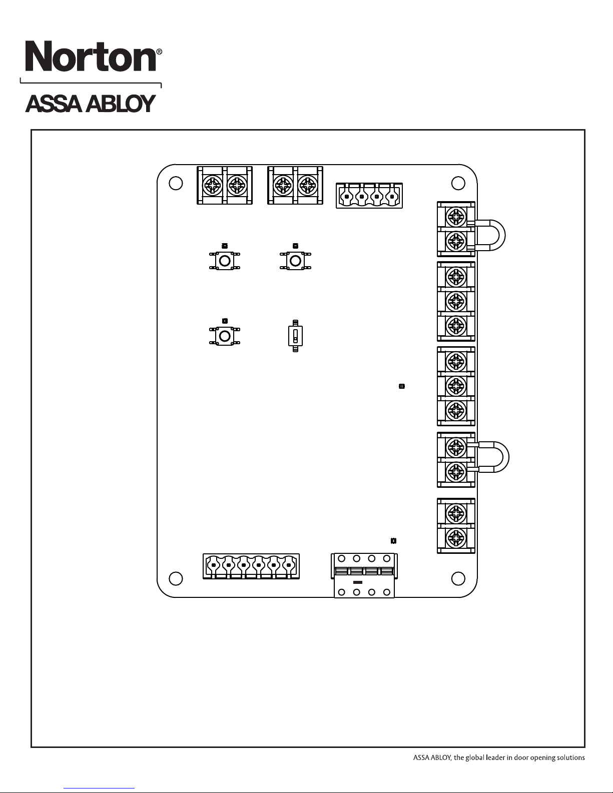
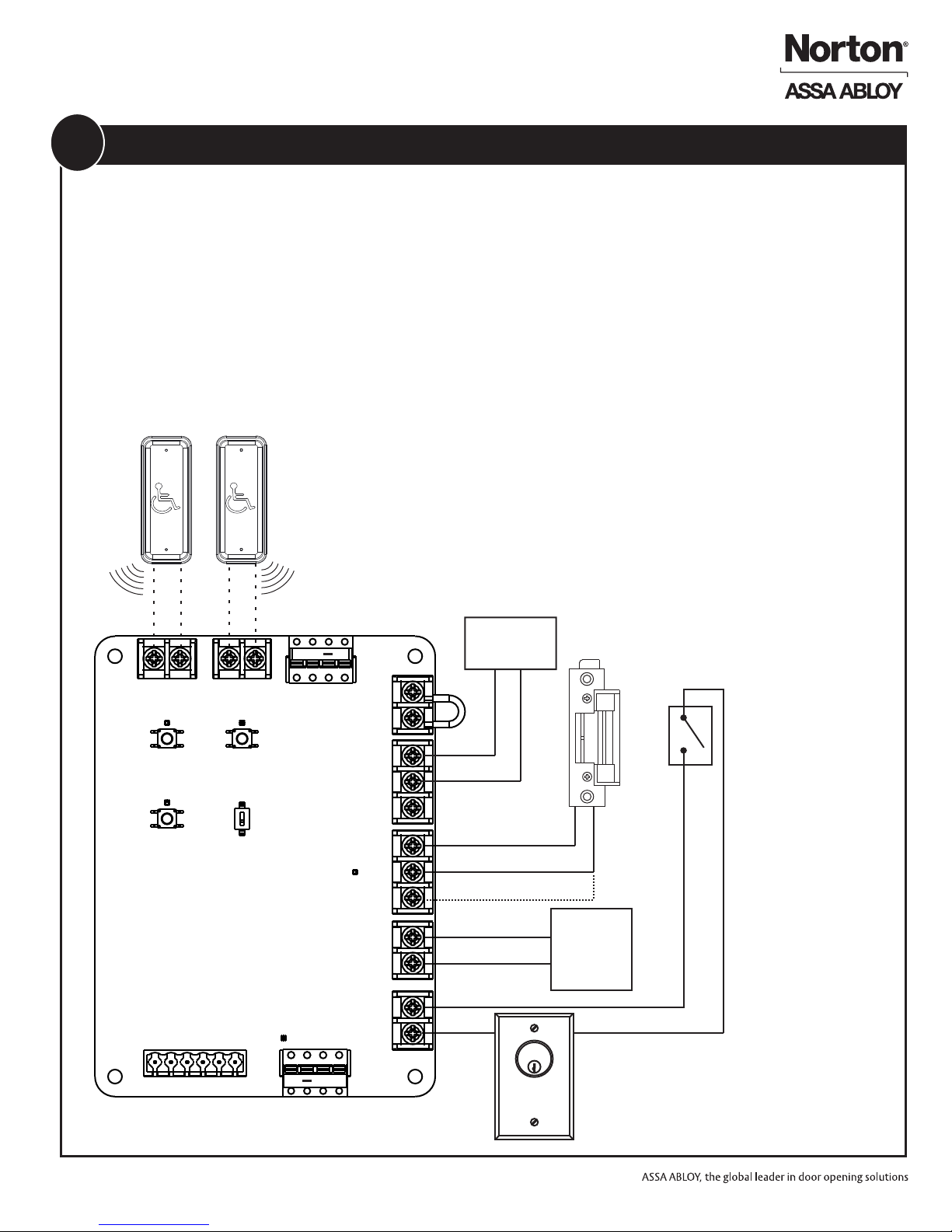
1. Refer to Figure 4. If the pushbuttons will be hard
wired, connect the INSIDE and OUTSIDE
pushbuttons to the WIM module contacts labeled
INSIDE BUTTON and OUTSIDE BUTTON.
a. Refer to Figure 4 and PRESS and RELEASE
the “INSIDE BUTTON” button.
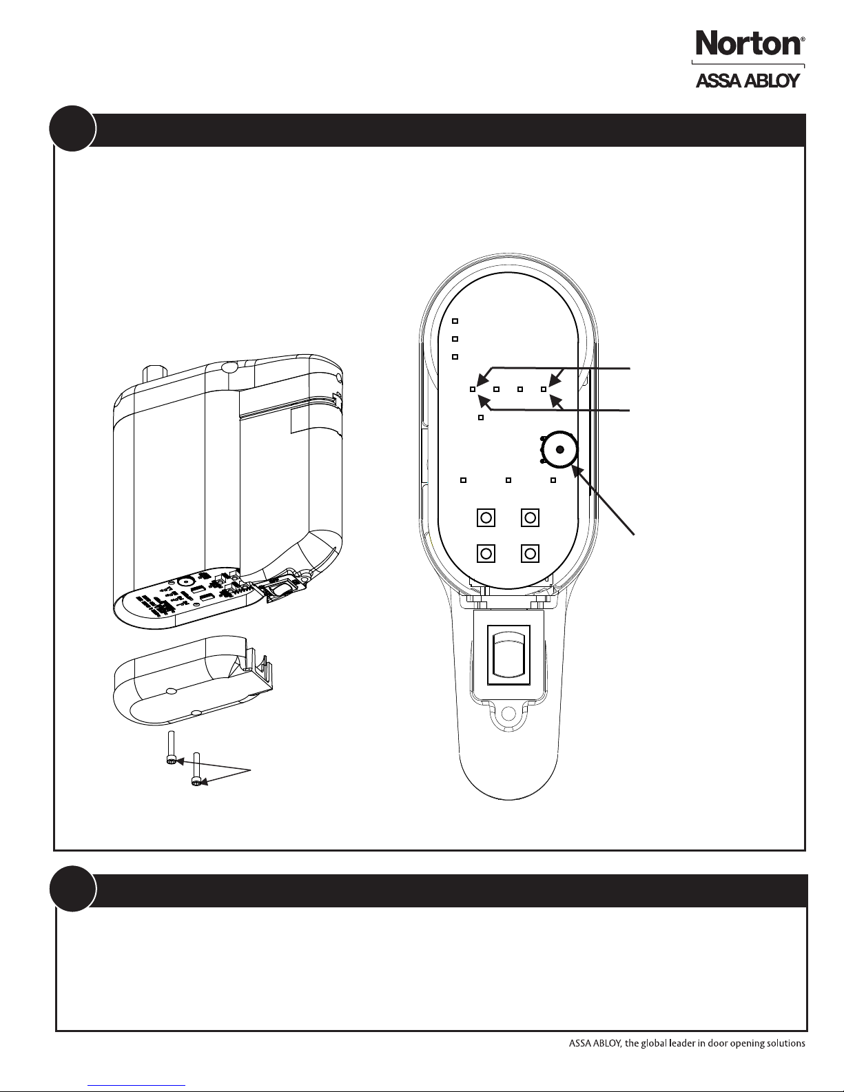
b. The Audible will beep and the LED above the
button will flash RED if no RF signals have been
learned or GREEN if an RF button is already
stored in memory. If the audible sounds a
steady beep and the RED LED lights flashes 4
times rapidly the RF memory is full and must be
reset in order to learn a new RF activation
signal.
NOTE:
An INSIDE activation is considered to be an input from
the SECURE side of the door. An INSIDE activation will
switch the LOCK contact, the ACCESS CTR output
contact, and send an activation signal to the door
operator.
2. If the INSIDE pushbutton will be connected using
RF activation, it must be learned to the WIM.
The pushbuttons may be connected by wire or wireless
connection to either the INSIDE activation or OUTSIDE
activation. If an optional Handheld Transmitter (not
included) was purchased it may be connected to either
the INSIDE or OUTSIDE activation inputs.
An OUTSIDE activation is considered to be an input
from the NON-SECURE side of the door. An OUTSIDE
activation will switch the LOCK contact, the ACCESS
CTR output contact, and send an activation signal to the
door operator ONLY if the ACCESS CTR INPUT contact
is CLOSED.
d. The LED will flash and the audible will beep 4
times if the RF signal was successfully learned.
e. If the pushbutton is not learned the audible will
beep for two seconds and exit learn mode.
c. Press and release the INSIDE pushbutton (or
optional handheld transmitter or optional
pushbutton) 2 times.
3. If the OUTSIDE pushbutton will be connected using
RF activation, it must be learned to the WIM.
a. Refer to Figure 4 and PRESS and RELEASE
the “OUTSIDE BUTTON” pushbutton.
c. Press and release the OUTSIDE pushbutton (or
optional handheld transmitter or optional
pushbutton) 2 times.
b. The Audible will beep and the LED above the
button will flash RED if no RF signals have been
learned or GREEN if an RF button is already
stored in memory. If the audible sounds a steady
beep and the RED LED lights flashes 4 times
rapidly the RF memory is full and must be reset
in order to learn a new RF activation signal.
d. LED D4 will flash and the audible will beep 4
times if the RF signal was successufully learned.
e. If the pushbutton is not learned the audible will
beep for two seconds and exit learn mode.
9Connect Pushbuttons and/or Handheld Remote to WIM
1. Refer to Figure 4 and PRESS and HOLD the
INSIDE BUTTON pushbutton on the WIM for 5
seconds
4. LED D4 will flash RED 4 times and the audible
will beep for 4 seconds
5. All learned RF codes are now erased.
3. Refer to Figure 4 and PRESS and HOLD the
OUTSIDE BUTTON pushbutton for 5 seconds
2. LED D3 will flash RED 4 times and the audible will
beep for 4 seconds
10 Erasing RF Codes from WIM