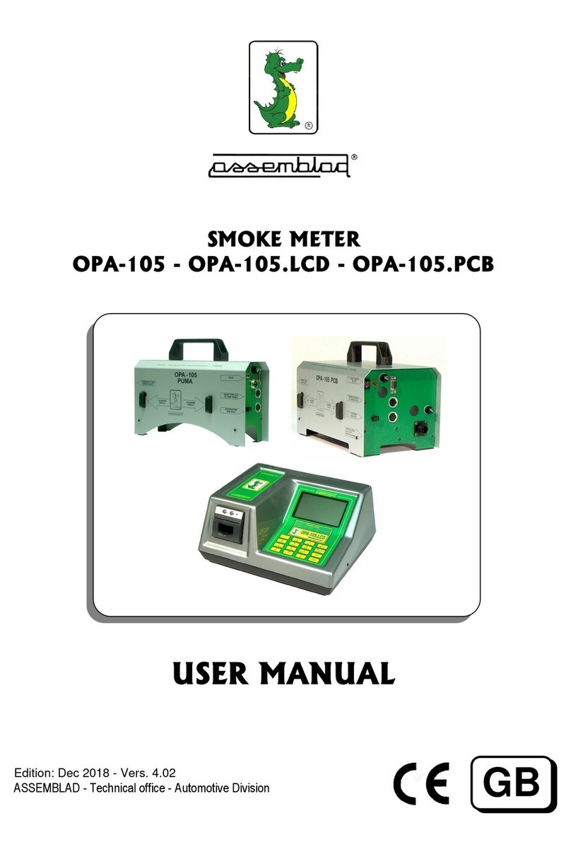
ASSEMBLAD INFRAGAS-196 User manual

Gas Analyzers:
INFRAGAS-196
INFRAGAS-196 PC-Module
(1 to 6 Gas Available)
OPERATING MANUAL
G
Edition: Sept. 2005. Vers. 5.39
ASSEMBLAD - Technical office - Automotive Division
Marte-C:\anno2005\196\M196gb539.doc

Assemblad Infragas-196 and Infragas-196 PC-Module * Operating manual
ASSEMBLAD S.r.l. - Costruzioni Elettroniche - Via Marzabotto, 4 - 50013 Campi Bisenzio - Firenze - Italy
Tel. +39-055-890485 - Fax +39-055-890496 - E-mail: info@assemblad.it - Web: www.assemblad.it 2
Note:

Assemblad Infragas-196 and Infragas-196 PC-Module * Operating manual
ASSEMBLAD S.r.l. - Costruzioni Elettroniche - Via Marzabotto, 4 - 50013 Campi Bisenzio - Firenze - Italy
Tel. +39-055-890485 - Fax +39-055-890496 - E-mail: info@assemblad.it - Web: www.assemblad.it 3
INDEX
1.0 DESCRIPTION .............................................................................................................................................4
1.1 GENERAL SPECIFICATIONS......................................................................................................................4
1.2 FRONT AND REAR PANEL..........................................................................................................................6
1.2.1 - Front Panel - ( Display and Keyboard )................................................................................................6
1.2.2 - Display ................................................................................................................................................7
1.2.3 - Keyboard..............................................................................................................................................8
1.2.4 Rear Panel ...........................................................................................................................................10
1.3 STANDARD ACCESSORIES .....................................................................................................................11
1.4 OPTIONAL ACCESSORIES (REFER TO PART NUMBER)............................................................................11
2DESCRIPTION OF OPERATIONS ...............................................................................................................12
2.1 INSTALLATION PROCEDURE ..................................................................................................................12
2.2 POWERING UP THE INSTRUMENTS ......................................................................................................12
2.3 USE OF THE INSTRUMENT......................................................................................................................12
2.4 CALIBRATION USING GAS BOTTLE........................................................................................................13
2.5 OXYGEN TRANSDUCER REPLACEMENT ..............................................................................................13
2.6 NITRIC OXIDE TRANSDUCER REPLACEMENT .....................................................................................13
3PERFORMING A TEST.................................................................................................................................14
3.1 STANDARD TEST......................................................................................................................................14
3.2 CARES AND NOTES .................................................................................................................................16
4.0 INFPLUS SOFTWARE..............................................................................................................................18
4.1. FEATURES OF THE PROGRAM........................................................................................................................18
4.2. INSTALLATION UNDER DOS ..........................................................................................................................18
4.3 RUNNING INFRAPLUS ....................................................................................................................................19
4.4 GAS ANALYZER SECTION...............................................................................................................................20
4.4a. Analyzer's status ..................................................................................................................................21
4.4b. Measurements .....................................................................................................................................21
4.4c. Hot keys................................................................................................................................................21
4.4d. Subform of manufacturer's data...........................................................................................................22
4.4e. Header..................................................................................................................................................22
5.0 REAL-TIME CLOCK (*) SETUP (MANUAL ADJ)...................................................................................23
6.0 OPERATIONS AVAILABLE FROM KEYBOARD.....................................................................................24
6.1 UPDATING THE CLOCK/CALENDAR ..................................................................................................24
6.2 SELECT THE RIGHT FUEL.................................................................................................................24
6.3 SELECT THE NUMBER OF ENGINE STROKES ..................................................................................24
7.0 RESIDUAL HC TEST ...............................................................................................................................25
8.0 AIRTIGHT SEAL TEST (NOT IN ALL MODELS) .....................................................................................26
9.0 TECHNICAL DATA ....................................................................................................................................27
10.0 - TROUBLESHOOTING AND MAINTENANCE.......................................................................................29
10.1 “ERR1” ... “ERR5” APPEARS ON CO, CO2 AND HC DISPLAYS....................................................................29
10.2 AUTOMATIC DRAINAGE OF CONDENSATE WATER ...........................................................................................29
10.3 ADDITIONAL TROUBLESHOOTING .................................................................................................................30
11.0 WARRANTY .............................................................................................................................................34
(*) = meaning OPTIONAL (depending of the Part Number or Model )

Assemblad Infragas-196 and Infragas-196 PC-Module * Operating manual
ASSEMBLAD S.r.l. - Costruzioni Elettroniche - Via Marzabotto, 4 - 50013 Campi Bisenzio - Firenze - Italy
Tel. +39-055-890485 - Fax +39-055-890496 - E-mail: info@assemblad.it - Web: www.assemblad.it 4
1.0 DESCRIPTION
Infragas 196 is a self-calibrating, multifunctional infrared exhaust gas analyzer, with
microprocessor based electronic circuitry.
1.1 GENERAL SPECIFICATIONS
1) CO, CO2 (*) and HC (*) measurements based upon a NDIR method.
2) O2 measurement (*) performed using an electrochemical transducer provided inside
on the rear panel of the instrument.
3) NOx measurement (*) performed using an electrochemical transducer provided
inside on the rear panel of the instrument.
4) RPM measurement (*) performed using the RPM Inductive Probe to be connected
with one of the cylinders and has a 2/4 stroke selection.
5) Ambient Pressure measurement (PRESS mb) based upon a specific pressure
transducer provided inside the instrument.
6) Ambient (AMB °C) and Oil Temperature (OIL °C) measurements performed using 2
separate temperature transducers provided one in the temperature probe (*) and the
other inside the instrument.
7) Lambda computations (*) obtained from gas measurement to test car manufacturer
spec's.
8) Real-Time Clock-Calendar (*) with battery backup allowing a data retention period of
5days (minimum). A special function is provided to update the Real-Time Clock
[Function not implemented on the model PC-Module ].
9) Automatic Condensate Drainage or automatic stop of gas suction if the condensate
drainage it’s insufficient.
10) Red and Green high-efficiency LED display to improve brightness [Function not
implemented on the model PC-Module ].
11) Functional 3-keys Membrane Keypad for a good protection against dust and oil. Two
red LED lamps monitor power on (ON) [besides, power on led blinks in case of
voltage

Assemblad Infragas-196 and Infragas-196 PC-Module * Operating manual
ASSEMBLAD S.r.l. - Costruzioni Elettroniche - Via Marzabotto, 4 - 50013 Campi Bisenzio - Firenze - Italy
Tel. +39-055-890485 - Fax +39-055-890496 - E-mail: info@assemblad.it - Web: www.assemblad.it 5
supply out of limits provided (220 Vac +/- 10 %)] and pump on (PUMP) [Function not
implemented on the model PC-Module ].
12) 1 Green high-efficiency display showing (*) O2,Lambda, CO Correct, NO, NOx,
RPM, Temp. Amb., Temp. Oil, 4S/2S selection and measurement selected on the 4
Green high-efficiency FUNCTION display [ O2%-FUNC ] [Function not implemented
on the model PC-Module ].
13) Gas filtering devices (condensate filter and particle filter) provided externally on the
rear panel for a quick maintenance.
14) Error and Special Operating condition messages on display to signal the occurrency
of situations like flow missing (Err1 .....) and condensate drainage problems (Con)
[Function not implemented on the model PC-Module ].
15) Self-calibration feature (using MEAS key) with "Cal" message on display and
automatic switch to gas suction at the end of this stage. Self-calibration does not
require removal of the hose from car exhaust pipe [Function not implemented on the
model PC-Module ].
16) Standard RS-232 Serial Interface (*) for future expansions for data processing
equipments and for other external equipments or for Service.

Assemblad Infragas-196 and Infragas-196 PC-Module * Operating manual
ASSEMBLAD S.r.l. - Costruzioni Elettroniche - Via Marzabotto, 4 - 50013 Campi Bisenzio - Firenze - Italy
Tel. +39-055-890485 - Fax +39-055-890496 - E-mail: info@assemblad.it - Web: www.assemblad.it 6
1.2 FRONT and REAR PANEL
1.2.1 - Front Panel - ( Display and Keyboard )
[Function not implemented on the model PC-Module ]
The front panel of INFRAGAS-196 is shown in the picture below:
Front panel of Infragas-196
1) CO display.
2) Multifunction FUNC display. Usually O2 is displayed and the other functions (Lambda,
RPM, Amb. Temp., Oil Temp., Amb. Press., NO, N0x , ....) are selected from keyboard
through the FUNC key and displayed.
3) display. It shows the correspondent simbol of the FUNCTION actived
on FUNC display.
4) HC display.
5) CO2 display.
6) Keyboard.
Note:
Your Gas analyzer may be different from the one shown above. It depends on the model
that you have purchased. This is the drawing for the full featured Standard Gas analyzer.
1 2 3 4
5 6

Assemblad Infragas-196 and Infragas-196 PC-Module * Operating manual
ASSEMBLAD S.r.l. - Costruzioni Elettroniche - Via Marzabotto, 4 - 50013 Campi Bisenzio - Firenze - Italy
Tel. +39-055-890485 - Fax +39-055-890496 - E-mail: info@assemblad.it - Web: www.assemblad.it 7
1.2.2. Display
INFRAGAS-196 in its full configuration has on the front panel 5 displays; displays are
splitted into 4 sets.
In the normal operating mode, after the first automatical calibration,displays are showing:
-CO =======> Carbon monoxide in Vol % from 0,00 to 9,99.
- CO2 =======> Carbon dioxide in Vol % from 00,0 to 19,9.
- HC =======> Hydrocarbons in ppm from 0000 to 5000.
- FUNC =====> Oxygen in Vol % from 0,00 to 21,4.
- =======> =Measure selected by keyboard using the FUNC key (see
below)
-during warm-up time the CO display shows the PEF value, HC shows the writing
“PEF”, and the FUNC display shows the Warm-up time remaning in minutes.
-during self-calibration stage CO and CO2 displays show "Cal" message on, the
FUNC display shows “ben “, the display shows “ “and the HC display
shows “4-SP”.
-in case of an insufficient flow on gas path occurs, on CO CO2 and HC displays
the messages “Err1”, “Err2” ..... “Err5” appears. In this conditions gas
measurement is inhibited (see Troubleshooting chapter)
-in case of condensate excess, on CO, CO2 and HC displays the message "Con"
appears indicating that instrument has stopped. During this stage any further
action is inhibited.
The display “FUNC ” is able to show several values of other measurements. Values
shows are: Oxygen, Lambda, RPM, Temperature, Barometric pressure, NO-Nitrogen
oxide, NOx - Nitrogen dioxide, CO Correct.
Measures are selected by the Keyboard using the FUNC key. The symbol that appears
on the display means:

Assemblad Infragas-196 and Infragas-196 PC-Module * Operating manual
ASSEMBLAD S.r.l. - Costruzioni Elettroniche - Via Marzabotto, 4 - 50013 Campi Bisenzio - Firenze - Italy
Tel. +39-055-890485 - Fax +39-055-890496 - E-mail: info@assemblad.it - Web: www.assemblad.it 8
1.2.3 Keyboard
Infragas 196 - Keyboard built-in front panel
Infragas 196 keyboard is composed of 3 keys each corresponding to a specific function,
and 2 warning lights.
1) MEAS (MEASURE) key : causes the instrument to start a new measurement by
initially performing a self-calibration stage. At the beginning the instrument switches
its internal valve to suck in ambient air. This stage requires approx. 30 sec. during
which the message "Cal" appears on CO and CO2 displays and data on gas displays
(including HC and O2) have no meaning. During this stage a new push of MEAS key
causes a termination of measurement sequence. At the end of self-calibration stage
the message "Cal" disappears and instrument automatically switches to suck in gases
from the hose, thus keeping the suction pump on until the MEAS key has been
pressed or after about 10 minutes from this operation.
2) FUNC key: allows selection of measurement to be displayed on FUNCTION
display [ FUNC + ]. Available measurements are:
-Oxygen
- Lambda value for many motor fuel ("L" on the rightmost digit)
- CO Correct
- Engine Oil Temperature
- Ambient Temperature the value displayed show the inside temperature
- Ambient Pressure in mbar
- RPM
- NO
- NOx
Each push of the FUNC key causes a switching of selection from top to bottom as
indicated by the corresponding symbol on display .
PUMP ON
MEAS FUNC P1

Assemblad Infragas-196 and Infragas-196 PC-Module * Operating manual
ASSEMBLAD S.r.l. - Costruzioni Elettroniche - Via Marzabotto, 4 - 50013 Campi Bisenzio - Firenze - Italy
Tel. +39-055-890485 - Fax +39-055-890496 - E-mail: info@assemblad.it - Web: www.assemblad.it 9
Regardless of selection made on FUNCTION display, a printing will include every
measurement performed by the instrument, even if not displaied.
3) P1 key: performs the print out of all measured and / or computed data (both
displayed or not) together with date and time and Workshop data (*) if provided.
Lambda value is relative to different propellant. A CO corr. parameter (corrected CO
value) is also printed (see Chapter 3).
If you need to have another report you must repeat the sequences: MEAS MEAS
and after “Cal” time P1 when the display has a stable appearance.
If the fuel setting is “PEt”, “LPG”, “MEt“, “PEtC”, “LPGC”, “MEtC“, the printing report
action is generated by means of unique key P1 ; if the fuel setting is Unleaded
Gasoline “Cat “ the printing report in generated by two actions on key P1, the first in
correspondence of the engine minimun rate then the second increasing the engine
rate up to 2500-3000 RPM; the second action on the key P1 to end the print report.
PEt = Petrol / Gasoline
MEt = Methane
LPG = Liquefied petroleum gas
PEt C = Unleaded Petrol / Gasoline Catalityc cars
MEt C = Methane Catalityc cars
LPGC = Liquefied petroleum gas Catalityc cars
You can select “PEt”, “LPG”, “MEt“, “PEtC”, “LPGC”, “MEtC“ during the “Cal” time
with FUNC key.
During the “Cal” time you can select the RPM mode 4St or 2St with P1 key in order
to set the right selection of RPM computation mode, referring to the engine type (4-
stroke or 2-stroke).
Pushing twice quickly this key when the analyzer is in standby will activate the
modem, if present, or deactivate it if the analyzer is still online.
4) ON -warning light: When it is flashing you have a problem on power line. Check for
line voltage (Main voltage = 230 Vac -10% +10% max).
5) PUMP -warning light: When this light is on the Pumps are working.

Assemblad Infragas-196 and Infragas-196 PC-Module * Operating manual
ASSEMBLAD S.r.l. - Costruzioni Elettroniche - Via Marzabotto, 4 - 50013 Campi Bisenzio - Firenze - Italy
Tel. +39-055-890485 - Fax +39-055-890496 - E-mail: info@assemblad.it - Web: www.assemblad.it 10
1.2.4 Rear Panel
The rear panel of INFRAGAS-196 is shown in the picture below:
Rear panel of Infragas-196
1) Condensate filter with gas inlet junction and a connection to the drainage valve.
2) Input water drainage.
3) Paper filter.
4) Gas outlet.
5) Temperature probe connector.
6) RPM probe connector.
7) Power supply socket and switch with fuse holder.
8) Water sensor.
9) Output water drainage
10) Drainage filter cup.
11) Standard RS-232 serial interface connector.
12) Empty / Not used
13) Particles filter.
14) Gas inlet.
0 - I
5 4 3 2 1
6
7
8
9
10
14
13
12
11

Assemblad Infragas-196 and Infragas-196 PC-Module * Operating manual
ASSEMBLAD S.r.l. - Costruzioni Elettroniche - Via Marzabotto, 4 - 50013 Campi Bisenzio - Firenze - Italy
Tel. +39-055-890485 - Fax +39-055-890496 - E-mail: info@assemblad.it - Web: www.assemblad.it 11
1.3 STANDARD ACCESSORIES
1) 5,80 m. hose with gas takeup tip.
2) Line power cord.
3) This manual.
1.4 OPTIONAL ACCESSORIES (Refer to Part number)
1) O2, CO2, HC, NO, NOx (*)
2) RPM. and RPM probe (*)
3) RS-232 (*)
4) Clock / Calendar (*)
5) 24 columns internal printer (*)
6) Oil temperature probe. (*)
7) Trolley.
8) Personalized print out

Assemblad Infragas-196 and Infragas-196 PC-Module * Operating manual
ASSEMBLAD S.r.l. - Costruzioni Elettroniche - Via Marzabotto, 4 - 50013 Campi Bisenzio - Firenze - Italy
Tel. +39-055-890485 - Fax +39-055-890496 - E-mail: info@assemblad.it - Web: www.assemblad.it 12
2DESCRIPTION OF OPERATIONS
2.1 INSTALLATION PROCEDURE
Remove the instruments from its package, install it on a trolley and connect accessories
as follows:
-connect RPM inductive probe, if provided, to the RPM connector placed on rear
panel;
-connect gas hose to the gas takeup tip being sure that the arrow on the filter
placed on the hose is in the direction of gas flow, then connect the other side of
the hose to the condensate filter on rear panel;
-connect temperature probe (*), if provided, to the rear panel connector;
Leave accessories always connected to the instrument, even if not used, to speed up
operations.
Warning:
once unpacked, the instrument may have internal NiCd battery discharged; this means
that real-time clock (*) has no date / time or a date / time value incorrect. In this case the
instrument must be connected to power and left powered on continuously for 24 hours to
insure full charge to internal NiCd battery. Then follow instructions to setup real-time clock.
2.2 POWERING UP THE INSTRUMENTS
Connect the line power cord to the instrument and switch it on; the instrument starts
printing the preamble. Wait for 15 min. (15 min it is the max. time) of warm-up time before
to start measurements on gases. The “FUNC” display show the warm-up time remaining.
Warm-up procedure doesn’t stop until the analyzer reach the requested temperature.
After this procedure the analyzer automatically performs a self-calibration then it will pass
to the exhaustion stage.
2.3 USE OF THE INSTRUMENT
1) After switching on, the instrument automatically sets to the following conditions:
-4-stroke engine type (RPM selection)
- O2 display (FUNCTION selection)

Assemblad Infragas-196 and Infragas-196 PC-Module * Operating manual
ASSEMBLAD S.r.l. - Costruzioni Elettroniche - Via Marzabotto, 4 - 50013 Campi Bisenzio - Firenze - Italy
Tel. +39-055-890485 - Fax +39-055-890496 - E-mail: info@assemblad.it - Web: www.assemblad.it 13
2) Insert take-up tip into the motorcar exhaust pipe, connect RPM probe to one of the
spark plugs cables and insert the temperature probe, if provided, into the oil
measuring rod receptacle.
3) After warm-up, instrument is ready to work; user may select, using FUNC key, one of
the auxiliary parameters available on FUNCTION display.
4) For gas measurement user presses MEAS key causing a self-calibration, after which
analyzer passes to a gas exhaustion stage. During this period the instrument, if gas is
present, periodically performs calibrating procedures (every 10 min.), while
automatically turns the pump off in case of gas lack for at least 10 min.
5) Operator may decide every time to print out data using P1 key, provided that pump is
on.
6) Once measurement has been completed, or whenever the operator wants, he may
decide to terminate gas exhaustion pressing MEAS key. However, if no action is
taken the instrument automatically turns the pump off after approx. 10 min. of
continuous operation, to preserve the pump from an useless stress.
2.4 CALIBRATION USING GAS BOTTLE
Manufacturer recommends a calibration with certified gas bottle (see Periodic
Maintenance Utility chapter) every twelve months. In some countries legislation defines
specific rules. Please contact our distributor for this periodical service activity.
2.5 OXYGEN TRANSDUCER REPLACEMENT
The oxygen transducer (*) life-time is 12 months (minimum) from the date of
delivery. Please contact our distributor for periodical replacement.
If the oxygen measurement, as well as the Lambda factor, are not shown during the
gas analysis it is the time to replace the oxygen sensor.
2.6 NITRIC OXIDE TRANSDUCER REPLACEMENT
The Nitric Oxide transducer (*) life-time is 18 months. It starts from the date of
delivery. Please contact our distributor for periodical replacement.

Assemblad Infragas-196 and Infragas-196 PC-Module * Operating manual
ASSEMBLAD S.r.l. - Costruzioni Elettroniche - Via Marzabotto, 4 - 50013 Campi Bisenzio - Firenze - Italy
Tel. +39-055-890485 - Fax +39-055-890496 - E-mail: info@assemblad.it - Web: www.assemblad.it 14
3PERFORMING A TEST
3.1 STANDARD TEST
Here the suggested procedure to test an engine is explained. It is also shown that
INFRAGAS-196 is a complete instrument to test in an exhaustive way the combustion
process and all the related devices of a car engine.
A) Install and switch on the instrument as explained in the preceding chapters.
B) Insert the gas takeup tip into the exhaust pipe.
C) Start the car engine and connect the RPM probe to one of the spark plugs cables,
being sure that the arrow on the body of the clamp is in the direction of cylinder.
D) Insert the temperature probe into the oil rod receptacle.
E) Using FUNC key select ambient temperature (AMB °C) and verify that its value is in
the range 0÷45 °C.
F) Using FUNC key select ambient pressure (PRESS mb) and verify that its value is in
the range 850÷1050 mbar.
G) Using FUNC key select oil temperature and wait until this parameter has reached 80
°C to be sure that engine has been properly warmed up. In case of lower temperature
keep the engine at about 2000 RPM until this temperature is reached.
H) When the proper oil temperature has been reached verify that RPM value is in the
range declared by the car manufacturer. In case of missing declaration RPM must not
exceed 1000 RPM.
I) If the 15 min. warm-up time is over, and Pump is OFF, press MEAS key and start
sampling exhaust gases (after a preliminary automatic self-calibration) until gas
readings are stable.
J) Print data (*) as a report of measurements done. Note that printer gives an additional
parameter: the corrected value of CO (CO corr). This paramenter is helpful in case of
leaks in the car exhaust pipe. Expression for CO corr is the following:
[CO] corr % = (#) x [CO%] / ( [CO%]+[CO2%] )
where (#) it is:
=15 for engines supplied with gasoline
= 12 for engines supplied with CH4
= 14 for engines supplied with GPL

Assemblad Infragas-196 and Infragas-196 PC-Module * Operating manual
ASSEMBLAD S.r.l. - Costruzioni Elettroniche - Via Marzabotto, 4 - 50013 Campi Bisenzio - Firenze - Italy
Tel. +39-055-890485 - Fax +39-055-890496 - E-mail: info@assemblad.it - Web: www.assemblad.it 15
if CO+CO2 is lower than 15, otherwise CO corr = CO
K) Compare following data with the corresponding ones declared by the car
manufacturer, or with expected values:
-CO
- CO2
- HC
- O2
- Lambda
Lambda is a parameter computed as follows:
Lambda = Num / Den
where:
Num:
21 x [ [CO2] + ([CO]/2) + [O2] + ((HCV/4) x 3,5 / (3,5 + [CO] / [CO2]) - 0.00877) x ([CO2] + [CO]) ]
Den:
[21+0.5628 x (([CO]/[CO2]) / (3,5+([CO] / [CO2]))]x[ 1+HCV/4 - 0,01754/2] x [CO2]+[CO]+[HC] x6 x10 -4 ]
where HCV = 1.85 for engine supplied with Gasoline
= 2.57 for engine supplied with GPL
= 4 for engine supplied with Methane
With [CO], [CO2] e [O2] = % in vol. and HC = ppm in vol.
If out of range data are measured, proceed with proper repairs and adjustments on
the motorcar.
L) After this work, print a report (*) of repairs and adjustments done.

Assemblad Infragas-196 and Infragas-196 PC-Module * Operating manual
ASSEMBLAD S.r.l. - Costruzioni Elettroniche - Via Marzabotto, 4 - 50013 Campi Bisenzio - Firenze - Italy
Tel. +39-055-890485 - Fax +39-055-890496 - E-mail: info@assemblad.it - Web: www.assemblad.it 16
3.2 CARES AND NOTES
-During tests be sure that RPM probe cord is not passing close to the other
cylinders or to the coil to avoid electronic noises.
-Be sure that arrow on the clamp of RPM probe is in the right direction (to the
cylinder).
-Sometimes RPM probe cannot measure RPM. It depends on very special kind of
plug cords strongly shielded. In such cases write manually RPM on printed report
as read from the engine speed indicator.
-Before every test, verify that condensate filter is not full of water to avoid an
unpredictable stop of the test itself for a possible automatic condensate drainage.
In this condition the analyzer must be switched OFF. The water must be removed
from the filter before powering up the device again.
-The internal porous septum of condensate filter must be cleaned periodically to
avoid flow missing. To do this first be sure that pump is off, then remove the small
silicone hose from the drainage valve pinchcock and unscrew carefully but firmly
the plastic glass of filter; the internal septum can be removed by acting on the
screw placed below it. The porous septum can be cleaned by bathing it with
gasoline or trichloroethylene. After a while, blow in compressed air and put it back
in its place. Finally screw the plastic glass, being sure that the o-ring is well
positioned, and put the small silicone hose in the valve pinchcock.
-Replace periodically the paper particle filter.
-If the "Err1"....”Err5” messages appears on FUNCTION display verify that:
-the gas tip and the hose are not blocked up or full of condensate;
-the condensate filter is not full;
-the particle filter is not damaged or blocked up;
-the gas exhaust of instrument is not blocked up. Note that in this case, after
having removed the block, it takes about 5 min. to restore O2 measurement
stability because of possible pneumatic stress of Oxygen sensor.
-for more information see the Troubleshooting chapter on this manual.
-It is advisable to remove, almost every day, water from gas hose by blowing in
compressed air in the direction of particle filter arrow (from the tip to the
instrument) obviously after having removed the hose from the instrument.

Assemblad Infragas-196 and Infragas-196 PC-Module * Operating manual
ASSEMBLAD S.r.l. - Costruzioni Elettroniche - Via Marzabotto, 4 - 50013 Campi Bisenzio - Firenze - Italy
Tel. +39-055-890485 - Fax +39-055-890496 - E-mail: info@assemblad.it - Web: www.assemblad.it 17
-When oil temperature is over maximum temperature the "or" message (out of
range) is displayed on FUNCTION display, if oil temp. is selected.
-The "or" message may also appear when Lambda are selected on FUNCTION
display. It means that these parameters are out of range (see ranges in Chapter
6).
-When temperature is below 0 °C or above 45 °C the "or" message is displayed on
FUNCTION display if amb. temp. is selected.
-When date / time values are not correct (out of range), date and time are not
printed by the instrument. A date / time setup procedure must be performed.
-The "ON" led on front panel blinks when power supply is out of its range
or IR emitter its broken.

Assemblad Infragas-196 and Infragas-196 PC-Module * Operating manual
ASSEMBLAD S.r.l. - Costruzioni Elettroniche - Via Marzabotto, 4 - 50013 Campi Bisenzio - Firenze - Italy
Tel. +39-055-890485 - Fax +39-055-890496 - E-mail: info@assemblad.it - Web: www.assemblad.it 18
4.0 INFPLUS Software
(Note: At the installation you can check on Assemblad Web Site www.assemblad.it , download section, if
there is any up dated version)
4.1. Features of the program
Infplus is a DOS program which is able to connect to ASSEMBLAD equipments
through their serial ports in order to take control of them and displaying and archiving their
data. Two database structures are also included in it, enabling the recording of the
emission target parameters issued by the car manufacturers and also a customer
database containing the data regarding both the customer and his vehicle.
Infplus has also the capability of generate many statistical or analytical reports and
redirecting them to the printer or to a text file, which is useful for importing from some
commercial spreadsheet programs for further examinations.
Inserting data in the databases, enabling their growth, is up to the user as
ASSEMBLAD doesn’t provide any prerecorded data regarding the vehicles.
4.2. Installation under DOS
In order to install InfraPlus on your computer running DOS please insert the diskette into
drive A: then type "A:install<enter>"
The software will be copied on your hard disk in the directory named "INFPLUS".
To run the program type "INFPLUS<enter>" from the DOS prompt of a DOS shell after
rebooting the computer in DOS mode.
A.pif file is also supplied in order to run the program from the Windows Desktop.

Assemblad Infragas-196 and Infragas-196 PC-Module * Operating manual
ASSEMBLAD S.r.l. - Costruzioni Elettroniche - Via Marzabotto, 4 - 50013 Campi Bisenzio - Firenze - Italy
Tel. +39-055-890485 - Fax +39-055-890496 - E-mail: info@assemblad.it - Web: www.assemblad.it 19
4.3 Running InfraPlus
Before running InfraPlus please check the connection between the PC's RS232 COMx
port and the analyzer.
When running InfraPlus a main menu with 6 items and the ASSEMBLAD logo will appear.
Don't worry if after few minutes the screen will change, it is just for saving the screen.
InfraPlus is shipped as default with these communication settings:
Port : COM1
Speed : 9600
Word : 8 bits
Stop : 1 bit
Parity : None
If the default port (COM1) doesn't match with your PC's port, you have to switch the
configured port to COM2 using the <F7> key.

Assemblad Infragas-196 and Infragas-196 PC-Module * Operating manual
ASSEMBLAD S.r.l. - Costruzioni Elettroniche - Via Marzabotto, 4 - 50013 Campi Bisenzio - Firenze - Italy
Tel. +39-055-890485 - Fax +39-055-890496 - E-mail: info@assemblad.it - Web: www.assemblad.it 20
WARNING!: Don't change at all the other parameters, please change only the COMx port
if required.
After that you can go to the gas analyzer section striking the <F1> key.
If an error message will appear, or the system respond very slowly, please check again
the wire connection as well as the communication parameters in use.
4.4 Gas Analyzer section
This section shows
-the analyzer's status
-all measurements made by the Infragas analyzer.
- a menu describing the hot keys availables.
- a subform containing vehicle manufacturer's data
-two header rows describing the vehicle under test
Table of contents
Other ASSEMBLAD Measuring Instrument manuals