Asutec ASM-150 User manual

ASM-150 BETRIEBSANLEITUNG | OPERATING MANUAL
Technische Änderungen vorbehalten. Alle Angaben ohne Gewähr. Alle Rechte liegen bei der ASUTEC GmbH.
Sub ect to technical modifications. No responsibility is accepted for the accuracy of this information. All rights are reserved by ASUTEC GmbH.
Document no. 85000014 – Version A – 2023/05/26 – M. Pohle
www.asutec.de | 1
BETRIEBSANLEITUNG
GERÄTETYPEN:
ASM-150
GERÄTEBEZEICHNUNG:
ASM: Stopper mit Dämpfung, pneumatisch betätigt
DOKUMENTNUMMER:
85000014
OPERATING MANUAL
DEVICE T PES:
ASM-150
DEVICE DESIGNATION:
ASM: Stop module with damping, pneumatically actuated
DOCUMENT NUMBER:
85000014
ASM-150-EW-15
ASM-150-EW-15-KI

ASM-150 BETRIEBSANLEITUNG | OPERATING MANUAL
Technische Änderungen vorbehalten. Alle Angaben ohne Gewähr. Alle Rechte liegen bei der ASUTEC GmbH.
Sub ect to technical modifications. No responsibility is accepted for the accuracy of this information. All rights are reserved by ASUTEC GmbH.
Document no. 85000014 – Version A – 2023/05/26 – M. Pohle
www.asutec.de | 2
INHALTSVERZEICHNIS
CONTENTS
1 Allgemeine inweise
1.1 Identifikationsdaten ............................................ 3
1.2 Bestimmungsgemäße Verwendung .................... 3
1.3 Sachwidrige Verwendung /
Vorhersehbarer Missbrauch ................................ 3
1.4 aftung ............................................................... 3
1.5 Garantieausschluss .............................................. 3
1.6 Umweltschutz / Entsorgung ................................ 4
1 General information
1.1 Identification data.................................................. 3
1.2 Intended use ......................................................... 3
1.3 Improper use / Foreseeable misuse ......................... 3
1.4 Liability.................................................................. 3
1.5 Exclusion of warranty ............................................. 3
1.6 Environmental protection / Disposal ........................ 4
2 Sicherheitshinweise
2.1 Warnhinweise in der Betriebsanleitung ............. 4
2.1.1 Erscheinungsbild und Struktur der
Warnhinweise ......................................... 4
2.1.2 Kennzeichnung der Warnhinweise ........ 4
2.2 Sicherheitsvorschriften für das Personal ............. 5
2.3 Voraussetzungen für den Einbauort .................. 5
2.4 Sicherheitsvorschriften für Pneumatik-
komponenten ...................................................... 6
2.5 Sicherheitsvorschriften für Betriebselektrik ....... 6
2 Safety instructions
2.1 Warnings in this manual ........................................ 4
2.1.1 Appearances and structure of the
warnings................................................... 4
2.1.2 Labeling of warnings ................................. 4
2.2 Safety regulations for personnel ............................. 5
2.3 Requirements for the installation location ............... 5
2.4 Safety regulations for pneumatic components ........ 6
2.5 Safety regulations for operating electronics............. 6
3 Technische Daten
3.1 Ausführung und Gewicht .................................... 6
3.2 Arbeitsbereich ..................................................... 6
3.3 Vortriebskraft ...................................................... 7
3.4 Staudruck ............................................................. 7
3.5 Wirksame Kolbenflächen, Kräfte ........................ 7
3.6 Funktion .............................................................. 7
3.7 Federkräfte .......................................................... 7
3.8 Temperaturbereich.............................................. 7
3.9 Betriebsdruck und Luftverbrauch ....................... 8
3 Technical details
3.1 Execution and weight ............................................ 6
3.2 Operating range .................................................... 6
3.3 Propulsive force ..................................................... 7
3.4 Ram pressure......................................................... 7
3.5 Effective piston areas, forces .................................. 7
3.6 Function ................................................................ 7
3.7 Spring forces ......................................................... 7
3.8 Temperature range ................................................ 7
3.9 Operating pressure and air consumption ................ 8
4 Transport ...................................................................... 8 4 Transport ........................................................................ 8
5 Montage
5.1 Sicherheit bei der Montage ................................ 8
5.2 Montage am Einsatzort....................................... 9
5.3 Druckluftanschluss............................................... 9
5.4 Montage induktiver Sensoren ............................ 9
5.5 Einstellung der Dämpfung .................................. 10
5.6 Abmessungen ...................................................... 11
5 Installation
5.1 Safety for installation ............................................. 8
5.2 Installation at the place of use ................................ 9
5.3 Air connection ....................................................... 9
5.4 Installation of inductive sensors .............................. 9
5.5 Ad ustment of damping ......................................... 10
5.6 Dimensions ........................................................... 11
6 Funktionsablauf ............................................................ 12 6 Functional sequence........................................................ 12
7 Wartung
7.1 Sicherheit bei der Wartung ................................. 13
7.2 Wartungsarbeiten ............................................... 13
7 Installation
7.1 Safety during maintenance .................................... 13
7.2 Maintenance work ................................................. 13
8 Typenschlüssel .............................................................. 14 8 Type codes ..................................................................... 14
9 Lieferumfang und Zubehör .......................................... 15 9 Scope of supply and accessories ...................................... 15
10 Einbauerklärung ........................................................... 16 10 Copy of the declaration of incorporation.......................... 16

ASM-150 BETRIEBSANLEITUNG | OPERATING MANUAL
Technische Änderungen vorbehalten. Alle Angaben ohne Gewähr. Alle Rechte liegen bei der ASUTEC GmbH.
Sub ect to technical modifications. No responsibility is accepted for the accuracy of this information. All rights are reserved by ASUTEC GmbH.
Document no. 85000014 – Version A – 2023/05/26 – M. Pohle
www.asutec.de | 3
1 ALLGEMEINE HINWEISE 1 GENERAL INFORMATION
1.1 IDENTIFIKATIONSDATEN 1.1 IDENTIFICATION DATA
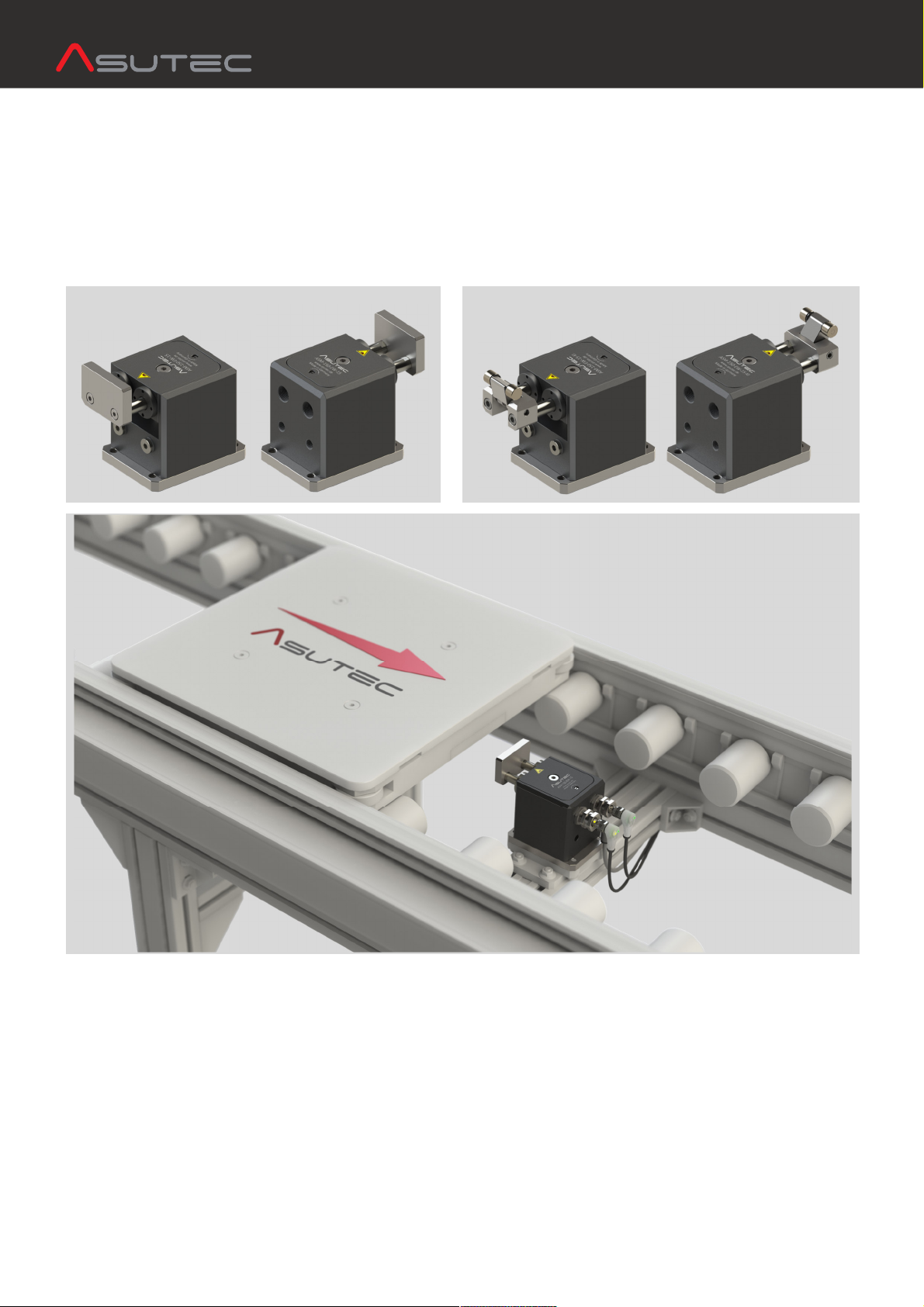
Typ-Bezeichnung:
Stopper mit Dämpfung, pneumatisch betätigt
erstelleranschrift, Kundendienst und Ersatzteile:
ASUTEC Gmb , Großer Forst 9, 72622 Nürtingen, Deutschland
Dokumentnummer und Version:
85000014 – Version A
Type designation:
Stop module with damping, pneumatically actuated
Manufacturer address, aftersales service and spare parts:
ASUTEC GmbH, Großer Forst 9, 72622 Nürtingen, Germany
Document number and version:
85000014 – Version A
1. BESTIMMUNGSGEMÄßE VERWENDUNG 1.2 INTENDED USE
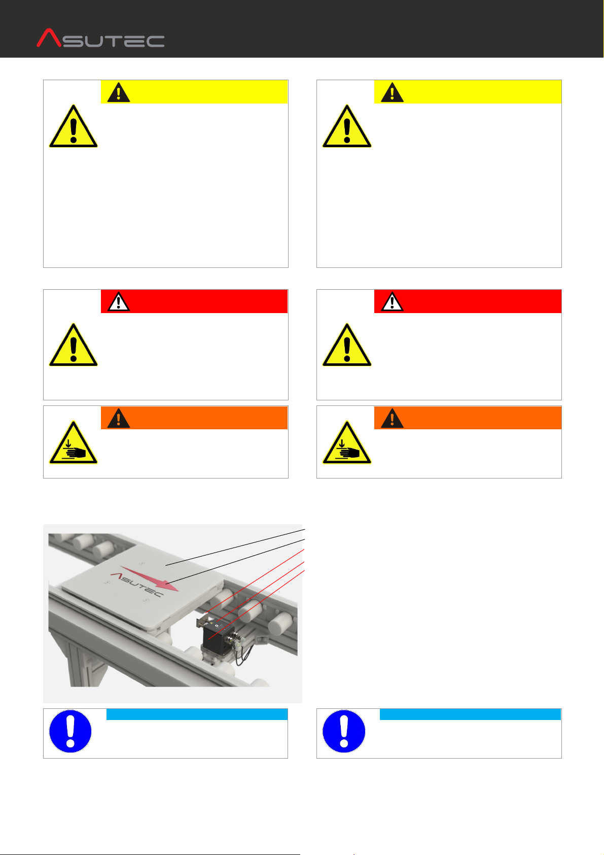
Der pneumatische Stopper:
- darf ausschließlich nur mit Druckluft betrieben werden!
- ist konzipiert für den Betrieb in geschlossenen Räumen!
- ist bestimmt für die Werkstückträgervereinzelung im
Transfersystem ohne Mitnehmer (Stauförderer)!
- stoppt einen oder mehrere auflaufende Werkstückträger
an einer definierten Werkstückträger-Anschlagfläche!
- ist bestimmt für den Einbau in eine Maschine – Die An-
forderungen der zutreffenden gesetzlichen Richtlinien für
Gesundheitsschutz und Maschinensicherheit müssen
beachtet und eingehalten werden!
- darf nur in der angegebenen Transportrichtung belastet
werden!
- darf nur im Originalzustand und mit Originalzubehör
betrieben werden!
- darf nur im Rahmen der definierten Einsatzparameter
(siehe Kapitel 3 technische Daten) verwendet werden!
The pneumatic stop module:
- may only be operated with compressed air!
- is designed for indoor operation!
- is intended for stopping and for the separation of the workpiece
carriers in the transfer system. In the stopping process, the
conveyor media continues moving under the workpiece carrier
(accumulation conveyor). A positive connection between
workpiece carrier and conveyor media is not allowed!
- stops one or more accumulated workpiece carriers on a defined
workpiece carrier stop surface!
- is intended for installation in a machine - The requirements of
the applicable legal directives for health protection and machine
safety must be observed and complied with!
- may only be loaded in the specified direction of transport!
- may only be used in its original condition and with original
accessories!
- may only be used within the scope of the defined application
parameters (see chapter 3 technical data)!
1.3 SACHWIDRIGE VERWENDUNG / 1.3 INPROPER USE /
VORHERSEHBARER MISSBRAUCH FORESEEABLE MISUSE
Eine sachwidrige Verwendung liegt vor, wenn der Stopper:
- nicht bestimmungsgemäß verwendet wird.
- in vibrationsgefährdeten oder explosionsgefährdeten
Bereichen betrieben wird.
- als Sicherheitsschalter verwendet wird.
- im Betrieb im direkten Kontakt mit verderblichen Gütern
steht.
An improper use is when the stop module:
- is not used according to the above provisions.
- is operated in vibration-prone or potentially explosive
atmospheres.
- is used as a safety switch.
- is in direct contact with perishable goods.
1.4 HAFTUNG 1.4 LIABILIT
Grundsätzlich gelten unsere Lieferungs- und Zahlungs-
bedingungen. Diese stehen dem Betreiber spätestens seit
Vertrags-abschluss zur Verfügung. Für Beistellungen von
Fremdherstellern durch den Auftraggeber und/oder von
Dritten übernimmt die Firma ASUTEC Gmb keine aftung
für deren Betriebssicherheit.
Gewährleistungs- und aftungsansprüche bei Personen- und
Sachschäden sind ausgeschlossen, wenn sie auf eine oder
mehrere der folgenden Ursachen zurückzuführen sind:
- nicht bestimmungsgemäße Verwendung des Geräts,
- Bedienungsfehler, unsachgemäße Montage,
Inbetriebnahme, Bedienung und Wartung der Maschine,
- mangelnde Wartung,
- Nichtbeachtung der inweise in der Betriebsanleitung
bezüglich Transportes, Lagerung, Montage, Inbetrieb-
nahme, Betrieb, Wartung und Reinigung des Geräts,
- eigenmächtige bauliche Veränderungen des Geräts,
Verwendung von Ersatzteilen, Zubehör, Anbaugeräten
und Sonderausstattungen, die von der Firma
ASUTEC Gmb nicht geprüft und freigegeben sind,
- eigenmächtige Veränderungen des Geräts
- unsachgemäß durchgeführte Reparaturen,
Katastrophenfälle durch Fremdkörpereinwirkung und
höhere Gewalt.
Our delivery and payment terms apply in principle. These have
been available to the operator at the latest since the conclusion of
the contract. For materials provided by foreign manufacturers by
the client and / or third parties, the company ASUTEC GmbH
assumes no liability for their reliability.
Warranty and liability claims for personal in ury and property
damage are excluded if they are attributable to one or more of the
following causes:
- improper use of the ASUTEC device,
- operator error, improper assembly, commissioning, operation
and maintenance of the machine,
- lack of maintenance,
- failure to observe the instructions in the operating instructions
regarding transport, storage, installation, commissioning,
operation, maintenance and cleaning of the device,
- unauthorized modifications of the device,
use of spare parts, accessories, attachments and special
equipment which have not been tested and approved by
ASUTEC GmbH,
- unauthorized modifications of the device.
- improperly executed repairs, catastrophes caused by external
forces and force ma eure.
1.5 GARANTIEAUSSCHLUSS 1.5 EXCLUSION OF WARRANT
Bei Nichtverwendung von Originalersatzteilen,
unsachgemäßer Bedienung und bei nicht
bestimmungsgemäßer Verwendung erlischt der
Gewährleistungsanspruch.
Für Ersatzteile kontaktieren Sie bitte die ASUTEC Gmb .
In case of non-use of original spare parts, improper operation and
in case of non-intended use, the warranty claim expires.
For spare parts please contact ASUTEC GmbH.

ASM-150 BETRIEBSANLEITUNG | OPERATING MANUAL
Technische Änderungen vorbehalten. Alle Angaben ohne Gewähr. Alle Rechte liegen bei der ASUTEC GmbH.
Sub ect to technical modifications. No responsibility is accepted for the accuracy of this information. All rights are reserved by ASUTEC GmbH.
Document no. 85000014 – Version A – 2023/05/26 – M. Pohle
www.asutec.de | 4
1.6 UMWELTSCHUTZ / ENTSORGUNG 1.6 ENVIRONMENTAL PROTECTION / DISPOSAL
Beim Austausch von Bauteilen ist auf eine sachgerechte
Entsorgung zu achten. Bitte beachten Sie die regional
gültigen Entsorgungsvorschriften.
When replacing components, please ensure proper disposal.
Please observe the regional disposal regulations.
SICHERHEITSHINWEISE 2 SAFET INSTRUCTIONS
.1 WARNHINWEISE IN DER BETRIEBSANLEITUNG 2.1 WARNINGS IN THIS MANUAL
.1.1 ERSCHEINUNGSBILDER UND STRUKTUR DER 2.1.1 APPEARANCES AND STRUCTURE OF THE WARNINGS
WARNHINWEISE
Für die unterschiedlichen Gefahrenstufen gelten
folgende Signalworte: The following signal words apply to the different hazard levels:
GEFAHR
DANGER
GEFA R weist auf eine gefährliche Situation,
die, wenn sie nicht vermieden wird, zum Tod
oder zu schweren Verletzungen führen kann.
DANGER indicates a dangerous situation which, if
not avoided, can lead to death or serious in ury.
WARNUNG
WARNING
WARNUNG weist auf eine gefährliche
Situation, die, wenn sie nicht vermieden wird,
zum Tod oder zu schweren Verletzungen
führen kann.
WARNING indicates a dangerous situation which,
if not avoided, can lead to death or serious in ury.
VORSICHT
ATTENTION
VORSIC T bezeichnet eine gefährliche
Situation, die, wenn sie nicht vermieden wird,
zu leichten oder mittelschweren Verletzungen
führen kann.
ATTENTION means a dangerous situation that, if
not avoided, can lead to minor or moderate in ury.
ACHTUNG
CAUTION
AC TUNG verweist auf Praktiken, die nicht im
Zusammenhang mit Personenschäden
verwendet werden.
CAUTION refers to practices that are not used in
connection with personal in ury.
.1. KENNZEICHNUNG DER WARNHINWEISE 2.1.2 LABELING OF WARNINGS
Die Betriebsanleitung ist mit Sicherheitshinweisen zum
sicheren Umgang mit dem ASUTEC Gerät versehen.
Diese Sicherheitshinweise können mit den unten
aufgeführten Piktogrammen gekennzeichnet sein:
The operating instructions are provided with safety instructions for
safe handling of the ASUTEC device.
These safety instructions can be identified by the pictograms
below:
PIKTOGRAMM BESC REIBUNG PICTOGRAM DESCRIPTION
Allgemeine Gefahrenstelle
General point of danger
Warnung vor elektrischer Spannung
Warning of electrical voltage
Warnung vor andverletzungen
Warning of hand in uries
Fußschutz benutzen
Use foot protection

ASM-150 BETRIEBSANLEITUNG | OPERATING MANUAL
Technische Änderungen vorbehalten. Alle Angaben ohne Gewähr. Alle Rechte liegen bei der ASUTEC GmbH.
Sub ect to technical modifications. No responsibility is accepted for the accuracy of this information. All rights are reserved by ASUTEC GmbH.
Document no. 85000014 – Version A – 2023/05/26 – M. Pohle
www.asutec.de | 5
. SICHERHEITSVORSCHRIFTEN FÜR DAS PERSONAL 2.2 SAFET REGULATIONS FOR PERSONNEL
VORSICHT
ATTENTION
Jede Person, die mit der Montage, Inbetrieb-
nahme, Bedienung und Instandhaltung des
ASUTEC Geräts befasst ist, muss bevor sie die
ersten andgriffe ausführt, die komplette
Betriebsanleitung und besonders das Kapitel
"Sicherheitshinweise" gelesen und verstanden
haben.
Every person involved in the installation,
commissioning, operation and maintenance of the
ASUTEC device must read and understand the
entire operating instructions, especially the chapter
"Safety instructions", before carrying out the first
hand operation.
Die Durchführung dieser Arbeiten darf nur durch geschultes
und eingewiesenes Fachpersonal erfolgen. Das Fachpersonal
muss Erfahrung im Umgang mit pneumatischen und
elektrischen Systemen besitzen. Das Fachpersonal muss
mindestens 18 Jahre alt sein und körperlich, sowie geistig
zum Bedienen des ASUTEC Geräts geeignet sein. Zu
schulendes, anzulernendes, einzuweisendes oder im Rahmen
einer allgemeinen Ausbildung befindliches Personal, darf nur
unter ständiger Aufsicht einer erfahrenen Person am ASUTEC
Gerät tätig sein.
This work may only be carried out by trained and instructed
personnel. The personnel must have experience in handling
pneumatic and electrical systems. The personnel must be at least
18 years old and physically and mentally able to operate the
ASUTEC device. Personnel who are in general training or who are
in instruction are only allowed to work on the ASUTEC device
under the permanent supervision of an experienced person.
.3 VORAUSSETZUNGEN FÜR DEN EINBAUORT 2.3 REQUIREMENTS FOR THE INSTALLATION LOCATION
GEFAHR
DANGER
Durch fehlerhafte elektrische Ausrüstung
besteht die Gefahr eines Stromschlags, der
schwere Verletzungen oder den Tod zur Folge
haben kann. Elektrische Anschlüsse müssen
den entsprechenden nationalen
Sicherheitsvorschriften zur Betriebselektrik
entsprechen. Nur Fachpersonal mit
elektrotechnischer Ausbildung darf an der
elektrischen Ausrüstung arbeiten.
Faulty electrical equipment may result in a risk of
electric shock which could result in serious in ury
or death.
Electrical connections must comply with the
relevant national safety regulations for the
operational electrical system. Only qualified
personnel with electrical training are allowed to
work on the electrical equipment.
WARNUNG
WARNING
Warnung vor unkontrollierten Bewegungen.
Der Einbauort des ASUTEC Geräts muss den
entsprechenden nationalen
Sicherheitsvorschriften der
Maschinensicherheit entsprechen.
Warning of uncontrolled movements. The
installation location of the ASUTEC device must
comply with the relevant national safety
regulations for machine safety.
Nicht in die offene Mechanik und in den Bewegungs- und
Arbeitsbereich des Geräts greifen. Am jeweiligen Einbauort
müssen zusätzlich Warnhinweise für Quetschgefahren
angebracht werden.
Do not reach into the open mechanics and into the movement and
working area of the device. At the respective installation location,
additional warning signs must be provided for crushing hazards.
Werkstückträger | Workpiece carrier
Transportrichtung | Transport direction
Anschlag des Stoppers | Stop plate of the stop module
Führungsgehäuse des Stoppers | Slide body of the stop module
Grundgehäuse des Stoppers | Basic body of the stop module
Zwischen dem Werkstückträger und dem Anschlag,
wenn sich ein Werkstückträger auf den Stopper zu bewegt.
Between workpiece carrier and the stop plate of the stop module,
when a workpiece carrier is moving towards the stop plate.
Zwischen dem Anschlag und dem Grundkörper des Stoppers,
wenn der Werkstückträger gedämpft wird.
Between the stop plate and the basic body of the stop module,
when the workpiece carrier is pushing the stop plate in.
3 Zwischen Grundgehäuse und Führungsgehäuse des Stoppers,
wenn der Stopper absenkt.
3 Between the basic body and slide body of the stop module,
when the stop module is lowering.
ACHTUNG
CAUTION
Veränderungen am Gerät wie z. B. die
Fertigung zusätzlicher Bohrungen und
Gewinden, bedürfen der vorherigen
Genehmigung der ASUTEC Gmb .
Changes to the device, for example, the
production of additional bores and threads
require the prior approval of ASUTEC GmbH.

ASM-150 BETRIEBSANLEITUNG | OPERATING MANUAL
Technische Änderungen vorbehalten. Alle Angaben ohne Gewähr. Alle Rechte liegen bei der ASUTEC GmbH.
Sub ect to technical modifications. No responsibility is accepted for the accuracy of this information. All rights are reserved by ASUTEC GmbH.
Document no. 85000014 – Version A – 2023/05/26 – M. Pohle
www.asutec.de | 6
.4 SICHERHEITSVORSCHRIFTEN FÜR 2.4 SAFET REGULATIONS FOR PNEUMATIC
PNEUMATIKKOMPONENTEN COMPONENTS
VORSICHT
ATTENTION
Es besteht die Möglichkeit von Verletzungen
durch hohe Betriebsdrücke im
Druckluftsystem der Maschine in die das
ASUTEC Gerät eingebaut ist.
An der pneumatischen Ausrüstung darf nur
Fachpersonal arbeiten, welches eine spezielle
Fachausbildung im Bereich Pneumatik hat und
welches Erfahrung im Umgang mit
Pneumatiksystemen hat.
There is the possibility of in uries due to high
pneumatic operating pressures in the compressed
air system of the machine in which the ASUTEC
device is installed. Pneumatic equipment may only
be operated by specialized personnel who have
specialized training in pneumatics and who has
experience in the handling of pneumatic systems.
Before any work on the pneumatic equipment the
entire machine must be depressurized.
Die pneumatische Ausrüstung des ASUTEC Geräts ist
regelmäßig auf Dichtheit und äußere Beschädigungen zu
überprüfen. Mängel müssen sofort beseitigt werden. Es
befindet sich ein Absperrventil in der Wartungseinheit der
Gesamtmaschine/Anlage. Dieses Ventil muss geschossen sein,
bevor Arbeiten an der pneumatischen Ausrüstung des
ASUTEC Geräts erfolgen.
The pneumatic equipment of the ASUTEC device must be regularly
checked for leaks and external damage. Defects must be rectified
immediately.
There is a shut-off valve in the maintenance unit of the entire
machine / system. This valve must be shot before working on the
pneumatic equipment of the ASUTEC device.
.5 SICHERHEITSVORSCHRIFTEN FÜR 2.5 SAFET REGULATIONS FOR OPERATING
BETRIEBS ELEKTRIK ELECTRONICS
GEFAHR
DANGER
Bei Arbeiten an elektrischer Ausrüstung
besteht die Gefahr eines Stromschlages, der
schwere Verletzungen oder den Tod zur Folge
haben kann. Elektrische Betriebsmittel müssen
den entsprechenden nationalen
Sicherheitsvorschriften zur Betriebselektrik
entsprechen. Nur Fachpersonal mit
elektrotechnischer Ausbildung darf an der
elektrischen Ausrüstung arbeiten.
There is a risk of electric shock when working on
electrical equipment that can result in serious
in ury or death. Electrical equipment must comply
with the relevant national safety regulations for
the operating electrical system. Only qualified
personnel with electrical training are allowed to
work on the electrical equipment.
3 TECHNISCHE DATEN 3 TECHNICAL DETAILS
3.1 AUSFÜHRUNG UND GEWICHT 3.1 EXECUTION AND WEIGHT
Geräteausführung: Grundkörper und Führungsgehäuse aus
Aluminium, Anschlag aus gehärtetem Stahl.
Luftdämpfung, mit Drosselschraube einstellbar.
Gewicht der Geräte:
Device design: Basic body and slide body made of aluminium and
stop plate made of hardened steel.
Air damping system, ad ustable with throttle screw.
Weights of the devices:
Typ EW / DW -15 Gewicht | Weight
ASM-150
-EW -15 -
-KI
2,21 kg
2,23 kg
-DW -15 -
-KI
2,18 kg
2,20 kg
3. ARBEITSBEREICH 3.2 OPERATING RANGE
v = … [m/min]
[1]
6 9 12 15 18 24 30 36
ASM-150 Gewicht WT [kg]
[2]
Weight of WT [kg]
[2]
5 - 150 5 - 100 5 - 100 5 - 95 5 - 90 5 - 55 5 - 35 5 - 25
[1]
Die angegebenen Werte für die zulässige Staulast und die zulässige Fördergeschwindigkeit
gelten, wenn nicht anders angegeben, bei einer Bandreibung von µ=0,07 zwischen
Werkstückträger (WT) und Transferband, bei einem Asutec Standardanschlag.
Zur Auslegung des Stoppers wird die Nutzung unseres Online- Produktfinders empfohlen.
Der angegebene Gewichtsbereich setzt sich aus dem Mindest-Werkstückträgergewicht
mmin und dem Maximal-Werkstückträgergewicht mmax zusammen.
[2] Einstellung der Dämpfung: Siehe Kapitel 5.5
[1]
The values, given in the table above for the permissible total weight of the accumulated workpiece
carriers (WT) and the permissible conveying speed, apply - if not otherwise stated - with a belt friction
of µ=0,07 between workpiece carrier and conveyor band and with the use of an ASUTEC standard
stop. To select the suitable stop module, we recommend the use of our online product finder. The
specified weight range is composed of the minimum workpiece carrier weight mmin and the maximum
workpiece carrier weight mmax.
[2] Ad ustment of damping: See chapter 5.5

ASM-150 BETRIEBSANLEITUNG | OPERATING MANUAL
Technische Änderungen vorbehalten. Alle Angaben ohne Gewähr. Alle Rechte liegen bei der ASUTEC GmbH.
Sub ect to technical modifications. No responsibility is accepted for the accuracy of this information. All rights are reserved by ASUTEC GmbH.
Document no. 85000014 – Version A – 2023/05/26 – M. Pohle
www.asutec.de | 7
3.3 VORTRIEBSKRAFT 3.3 PROPULSIVE FORCE
Um ein einwandfreies Absenken zu gewährleisten, dürfen
die Vortriebskräfte nicht überschritten werden:
In order to ensure a perfect lowering movement of the stop
module, the following propulsive forces must not be exceeded:
ASM-150: F
Rmax
= 206 N ASM-150: F
Rmax
= 206 N
Ist die Vortriebskraft zu groß, kann der Stopper nicht
absenken, da die Reibung zwischen dem Anschlag und dem
Werkstückträger nicht überwunden werden kann. Die jeweils
angegebenen Werte der maximalen Vortriebskraft basieren
auf einem Reibwert μ = 0,2 zwischen dem Anschlag und dem
Werkstückträger.
Damit gewährleistet ist, dass der Anschlag die Dämpfungs-
endlage erreicht, dürfen folgende Mindestvortriebskräfte
nicht unterschritten werden: ASM-150 F
Rmin
= 3,43 N
If the propulsive force is too high, the stop module cannot lower
because of the friction between the stop plate and the stop surface
of the workpiece carrier. The specified values of the maximum
propulsive force are based on a coefficient of friction μ = 0.2
between the stop and the workpiece carrier.
In order to ensure that the stop plate reaches the damping end
position, the following minimum propulsive forces must not be less
than: ASM-150 F
Rmin
= 3,43 N
3.4 STAUDRUCK 3.4 RAM PRESSURE
ACHTUNG
CAUTION
Wenn mehrere Werkstückträger in Transfer-
systemen aufgestaut und später vereinzelt
werden, muss darauf geachtet werden, dass
beim Freigeben des ersten Werkstückträgers,
die Gesamtmasse der folgenden
Werkstückträger das maximal zu stoppende
Gewicht zu keiner Zeit überschreiten.
If several workpiece carriers in transfer systems get
accumulated and get separated later, it must be
ensured that when releasing the first workpiece
carrier (WT) the total mass of the following work-
piece carriers does not exceed the maximum
weight to be stopped at any time.
Der maximale Staudruck ist abhängig von:
- der Reibung zwischen WT und Transfersystem
(Zahnriemen, Staurollenkette, Flachplattenkette, …)
- der Reibung zwischen WT und Anschlag
- der Position des WT Anschlags
- den Umgebungsbedingungen
(Staub, Anzahl der pneumatischen Verbraucher im System)
The maximal ram pressure depending on:
- the friction between the WT and conveyor media
(belt, accumulation roller chain, flat top chain, …)
- the friction between the WT and stop plate
- the position of the WT stop plate
- the environmental conditions
(Dust, pneumatic consumers in the system etc.)
3.5 WIRKSAME KOLBENFLÄCHEN, KRÄFTE 3.5 EFFECTIVE PISTON AREAS, FORCES
Die Kräfte sind abhängig vom pneumatischen Druck, von der
Kolbenfläche und von der Federkraft.
Bei den jeweiligen Arbeitsbewegungen werden folgende
Kolbenflächen mit Druckluft beaufschlagt:
Kolbenfläche zum Absenken: 1583 mm²
Kolbenfläche zum ochfahren (bei DW-Version): 1963 mm²
Kolbenfläche z. Ausfahren des Dämpfungskolbens: 982 mm²
The forces are dependent on the pneumatic pressure, the piston
surface and the spring force.
During the respective working movements, the following piston
surfaces are sub ected to compressed air:
Piston surface for lowering: 1583 mm²
Piston surface to raise (only for DW-version): 1963 mm²
Piston surface for extending the damping piston: 982 mm²
3.6 FUNKTION 3.6 FUNCTION
Die pneumatischen Stopper ASM-150 sind Stopper mit
Dämpfung.
Wenn ein Werkstückträger gegen den Anschlag des Stoppers
schlägt, so wird die Luftkammer komprimiert und die
komprimierte Luft entweicht durch den Öffnungsspalt der
Einstellschraube. Somit wird der Werkstückträger sanft bis
zum Stillstand gedämpft.
Die Dämpfung ist eine Luftdämpfung und kann über eine
Drosselschraube fein eingestellt werden.
Wenn ein Werkstückträger auf den Anschlag fährt, gedämpft
wird und den Anschlag einfährt, so bleibt der Anschlag
anschließend im eingefahrenen Zustand. Es wirkt keine
Gegenkraft auf den Anschlag, die bewirken würde, dass der
Anschlag ausfährt, wenn zum Beispiel der Werkstückträger
bei einer Bearbeitungsstation ausgehoben wird.
Das Ausfahren des Anschlags erfolgt durch eine interne
Ventilsteuerung im Stopper, beim Absenken, wenn der
Stopper die untere Position erreicht hat.
The pneumatic stop modules ASM-150 are stop modules with
damping.
If a workpiece carrier strikes against the stop plate of the stop
module, the air chamber is compressed and the compressed air
escapes through the opening gap of the throttle screw. Thus, the
workpiece carrier is gently damped to a stop.
The damping is with air and can be finely ad usted via a throttle
screw.
If the workpiece carrier will be damped, the stop plate will be
pushed in. The stop plate will stay in this position. There are no
forces that would try to move the stop plate even the workpiece
pallet is not pushing against the stop plate.
The stop plate is extended by an internal valve control in the stop
module when lowering when the stop module has reached the
lower position.
3.7 FEDERKRÄFTE 3.7 SPRING FORCES
Die Stopper ASM-150 haben in ihrer Grundausführung „EW“
= Einfachwirkend“ eine Druckfeder, die den Stopper in
dessen Sperrstellung, obere, bzw. aufgestellte Position hält.
Die Federkräfte betragen hierbei:
Aufgestellte Position: F
1
= 86 N
Abgesenkte Position: F
2
= 265 N
The stop modules ASM-150 in its basic version "EW" = "single-
acting", have a compression spring that moves the stop module
into its blocking, upper or raised position.
The spring forces are:
Raised position: F
1
= 86 N
Lowered position: F
2
= 265 N
3.8 TEMPERATURBEREICH 3.8 TEMPERATURE RANGE
Standardausführung: -20°C bis +80°C
(- = itzebeständige Ausführung: -20°C bis +180°C)
Standard version: -20°C to +80°C
(-H = Heat resistant -20°C to +180°C)

ASM-150 BETRIEBSANLEITUNG | OPERATING MANUAL
Technische Änderungen vorbehalten. Alle Angaben ohne Gewähr. Alle Rechte liegen bei der ASUTEC GmbH.
Sub ect to technical modifications. No responsibility is accepted for the accuracy of this information. All rights are reserved by ASUTEC GmbH.
Document no. 85000014 – Version A – 2023/05/26 – M. Pohle
www.asutec.de | 8
3.9 BETRIEBSDRUCK UND LUFTVERBRAUCH 3.9 OPERATING PRESSURE AND AIR CONSUMPTION
Betriebsdruck: p
min
= 4 bar | p
max
= 8 bar Operating pressure: p
min
= 4 bar | p
max
= 8 bar
p = 4 bar p = 5 bar p = 6 bar p = 7 bar p = 8 bar
Zyklus = Absenken + Anschlag
ausfahren + Aufstellen
Cycle = Lowering + extend stop plate +
raising the stop
V [cm³]
[3]
Je Zyklus
Each cycle
Q [Nl]
Je Zyklus
Each cycle
Q [Nl]
Je Zyklus
Each cycle
Q [Nl]
Je Zyklus
Each cycle
Q [Nl]
Je Zyklus
Each cycle
Q [Nl]
ASM-150-EW-15
ASM-150-DW-15
43,2 cm³
72,6 cm³
0,22 Nl
0,37 Nl
0,27 Nl
0,44 Nl
0,31 Nl
0,51 Nl
0,35 Nl
0,59 Nl
0,40 Nl
0,66 Nl
[3] Die Angegebenen Werte der Zylindervolumen V beziehen sich nur auf die Kolbenabmessungen
im Gerät. Luftkanalbohrungen und Zuleitungsquerschnitte, die im Betriebseinsatz mit Druckluft zu
Befüllen sind, werden nicht berücksichtigt.
[4] Die oberhalb angegebenen Tabellenwerte der Luftverbräuche Q sind teilweise aufgerundet, bzw.
deren letzte Nachkommastelle erhöht.
[3] The values given for the cylinder volume V only refer to the piston dimensions in the device. Air duct
bores and supply line cross-sections that must be filled with compressed air during operation are not taken
into account.
[4] Some of the table values for air consumption Q given above have been rounded up or the last decimal
place has been increased.
Der Luftverbrauch
Q
in Normliter (Nl) kann mit folgender
Formel
berechnet werden:
Q
∙,
ierbei ist: Q … Luftverbrauch in Normliter (Nl)
V
… Zylindervolumen (cm³)
p
… Pneumatischer Druck in MPa (6 bar = 0,6 MPa)
The air consumption
Q
in liter (Nl) can be calculated by using the
formula:
Q
∙
,
Here is: Q … Air consumption in liter (Nl)
V … Cylinder volume (cm³)
p
… Supply pressure in MPa (6 bar = 0,6 MPa)
4 TRANSPORT 4 TRANSPORT
VORSICHT
ATTENTION
Das Gerät wird üblicherweise von and
transportiert. Bei höherem Gewicht ist das
Produkt mit einem ebezeug anzuheben und
mit einem geeigneten Transportgerät zu
transportieren.
Tragen Sie beim Transport Sicherheitsschuhe.
The device is usually transported by hand. If the
product is heavier, it must be lifted with a lifting
gear and transported with suitable transport
equipment.
Wear safety shoes during transport.
5 MONTAGE 5 INSTALLATION
5.1 SICHERHEIT BEI DER MONTAGE 5.1 SAFET FOR INSTALLATION
WARNUNG
WARNING
Warnung vor unkontrollierten Bewegungen.
Während das Gerät an einer Energiequelle
angeschlossen ist, kann es unkontrollierte
Bewegungen ausführen. Vor Montage-
arbeiten müssen Sie die elektrischen und
pneumatischen Energiezuführungen
abschalten und ein unbeabsichtigtes
Wiedereinschalten verhindern, z. B. aupt-
schalter der Gesamtmaschine abschließen und
ein entsprechendes Warnschild anbringen.
While the device is connected to an energy source,
it can perform uncontrolled movements.
Before starting the installation work, you must
switch off the electrical and pneumatic power
supply and prevent unintentional restarting.
For example, switch off the entire machine on the
main switch and lock the switch against re-
activation. Attach an appropriate warning sign.
Bei den einfachwirkenden Varianten „EW“, ist
bei der Montage so lange zu warten, bis der
Stopper im drucklosen Zustand die obere
Stellung erreicht hat.
With the single acting variants "EW", it is
necessary to wait during installation until the
stopper has reached the upper position in the
depressurized state.
GEFAHR
DANGER
Durch fehlerhafte elektrische Montage be-
steht die Gefahr eines Stromschlages, der
schwere Verletzungen oder den Tod zur Folge
haben kann. Nur Fachpersonal mit elektro-
technischer Ausbildung darf an der
elektrischen Ausrüstung Arbeiten.
Faulty electrical installation may result in a risk of
electric shock which can result in serious in ury or
death. Only qualified personnel with electrical
training are allowed to work on the electrical
equipment.

ASM-150 BETRIEBSANLEITUNG | OPERATING MANUAL
Technische Änderungen vorbehalten. Alle Angaben ohne Gewähr. Alle Rechte liegen bei der ASUTEC GmbH.
Sub ect to technical modifications. No responsibility is accepted for the accuracy of this information. All rights are reserved by ASUTEC GmbH.
Document no. 85000014 – Version A – 2023/05/26 – M. Pohle
www.asutec.de | 9
5. MONTAGE AM EINSATZORT 5.2 INSTALLATION AT THE PLACE OF USE
ACHTUNG
CAUTION
Befestigungselemente sind im Lieferumfang
nicht enthalten und müssen getrennt
beschafft werden.
Die Befestigung erfolgt mit 4 Schrauben M8
von unten. Das Anzugsmoment beträgt
jeweils 20 Nm.
Fastening elements are not included in the scope of
delivery and must be procured separately.
The stopper is fastened with 4 x M8 screws from
below. The tightening torque of the screws is 20
Nm.
Die Grundplatte des Stoppers ASM-150 ist aus Stahl und hat
eine Stärke von 10 mm. Es ist zu beachten, dass die
Befestigungsschrauben weniger als 10 mm tief in das
Gewinde eingeschraubt werden können, da es keine
Durchgangsgewindebohrungen sind. Wird diese maximale
Einschraubtiefe überschritten, dann wird beim Anziehen der
der Befestigungsschrauben der Stopper beschädigt.
The base plate of the ASM-150 stopper is made of steel and has a
thickness of 10 mm. It should be noted that the mounting screws
can be screwed less than 10 mm deep into the thread as they are
not through-threaded holes. If this maximum screw-in depth is
exceeded, the stopper will be damaged when the fastening screws
are tightened.
5.3 DRUCKLUFTANSCHLUSS 5.3 AIR CONNECTION
Die Stopper ASM-150
werden als einfach-
wirkende (EW) und
doppeltwirkende (DW)
Varianten angeboten.
Sowohl in der EW-
Ausführung, als auch bei
der DW-Ausführung sind
zwei Luftanschluss-
bohrungen vorhanden.
Mit dem Luftanschluss P1
wird der Stopper
abgesenkt.
Bei der DW-Ausführung
wird der Luftanschluss P2
verwendet, um den
Stopper nach oben in die
Sperrstellung zu fahren.
Luftanschlussmöglichkeiten
gibt es auf der Rückseite
und Vorderseite.
EW
DW
The stop modules ASM-150
are offered as single acting
variants (EW) and double
acting variants (DW).
Both the EW version and
the DW version have two
air connection holes.
The stopper is lowered with
the air connection P1.
In the DW version the air
connection P2 is used to
move the stopper up into
the blocking position.
There are air connection
options on the back and
front.
When delivered, the rear air
connection holes are sealed
with blind plugs and can be
moved to the front if
necessary.
P1
P2
Im Anlieferungszustand sind die hinteren Luftanschluss-
bohrungen mit Blindstopfen verschlossen und können bei
Bedarf nach vorne gewechselt werden.
5.4 MONTAGE INDUKTIVER SENSOREN 5.4 INSTALLATION OF INDUCTIVE SENSORS
Die obere und die abgesenkte
Position des Anschlags kann bei
dem Stopper ASM-150 mit
induktiven Sensoren abgefragt
werden.
Für die Montage der induktiven
Sensoren werden Klemmhalter
M16x1 in kurzer Ausführung
verwendet.
In diese Klemmhalter werden die
induktiven Sensoren M12x1
bündig eingebaut.
Verwenden Sie Sensoren mit
4 mm Bemessungsschaltabstand.
Die Gewindebohrungen am Gerät
sind im Anlieferungszustand mit
Verschlussstopfen verschlossen.
Für die Montage der Klemmhalter
müssen diese Verschlussstopfen
entfernt werden.
The upper and lowered position of
the stop module can be queried with
inductive sensors at the stop modules
ASM-150
For mounting the inductive sensors,
clamp holders M16x1 in short version
are used.
In these clamp holders, the inductive
proximity switches (M12x1) can be
flush mounted.
Use inductive proximity switches with
a rated operating distance of 4 mm.
The tapped holes on the device are
sealed with the plug when delivered.
For mounting the clamp holders,
these sealing plugs must be removed.

ASM-150 BETRIEBSANLEITUNG | OPERATING MANUAL
Technische Änderungen vorbehalten. Alle Angaben ohne Gewähr. Alle Rechte liegen bei der ASUTEC GmbH.
Sub ect to technical modifications. No responsibility is accepted for the accuracy of this information. All rights are reserved by ASUTEC GmbH.
Document no. 85000014 – Version A – 2023/05/26 – M. Pohle
www.asutec.de | 10
Um die obere oder abgesenkte Stellung des
Stoppers abzu-fragen, werden die Klemmhalter
M16x1 mit induktiven Sensoren in die dafür
vorgesehenen Bohrungen auf der Rückseite des
Geräts geschraubt. ierbei ist zu beachten, dass
keine mechanische Begrenzung vorhanden ist, die
die Einschraubtiefe des Klemmhalters vorgibt.
To query the upper or lowered position of the
stop module, the M16x1 clamp holders with
inductive proximity switches are screwed into
the holes provided on the back side of the
device. It should be noted that there is no
mechanical limit that specifies the depth of the
clamp holder.
ACHTUNG
CAUTION
Wenn die Klemmhalter zu tief
eingeschraubt werden, dann
kommen sie mit bewegenden
Teilen des Stoppers in Berührung.
ierdurch wird der Stopper in
seiner ubbewegung blockiert.
If the clamp holders are screwed
in too deeply, they will come into
contact with the moving parts of
the stopper. As a result, the
stopper is blocked in its lifting
movement.
Bei der Montage ist in diesem Fall folgendermaßen vorzugehen: During assembly, proceed as follows:
Entfernen Sie die Verschlusstopfen und beginnen Sie mit der
Montage der Stellungsabfrage für die obere Position
Befestigen Sie den induktiven Näherungsschalter im
Klemmhalter und schrauben Sie den Klemmhalter so weit in das
Gerät hinein, bis das Abfrageelement die Vorderseite des
induktiven Näherungsschalters leicht berührt.
Schrauben Sie den Klemmhalter etwa ein bis zwei Umdrehungen
zurück, um somit einen Schaltabstand von etwa 1 mm bis 2 mm
einzustellen.
Kontern Sie den Klemmhalter mit der dazugehörigen Mutter.
Bei der Montage der Abfrage für die abgesenkte Stellung des
Stoppers ist der Stopper in seine abgesenkte Position zu
drücken. Die Montage erfolgt in den oben beschriebenen
Schritten bis .
Remove the plugs and start assembling the position query for
the upper position.
Fasten the inductive proximity switch in the clamp holder and
screw the clamp holder into the device until the sensing
element lightly touches the front of the inductive proximity
switch.
Screw the clamping bracket back about one to two turns to
set a switching distance of approx. 1 mm to 2 mm.
Lock the clamp holder with the supplied nut.
When assembling the query for the lowered position, the stop
module must be pressed in its lowered position.
The assembly takes place in the steps to described
above.
5.5 EINSTELLUNG DER DÄMPFUNG 5.5 ADJUSTMENT OF DAMPING
Die Dämpfwirkung kann bei den Geräten der
Baureihe ASM-150 mit einem Schlitz-
Schraubendreher auf der Geräteoberseite
eingestellt werden.
Auf dem Gerät ist die Einstellrichtung markiert.
ierbei bedeutet:
+ … Zunahme der Dämpfwirkung
- … Verringerung der Dämpfwirkung
Mit der Einstellschraube kann die Dämpfwirkung
im gewissen Bereich eingestellt werden. Als
Erfahrungswert kann angegeben werden, dass
bei eingestellter Dämpfung Gewichte im Bereich
von ± 50% des eingestellten Gewichts gut
gedämpft werden können.
The damping effect can be ad usted on the
top of the device at the ASM-150 series by
using a slotted screwdriver.
The setting direction is marked on the
device.
The marks have the following meaning:
+ ... increased damping effect
- ... reduce the damping effect
The damping effect can be ad usted within
a certain range. As an experience value can
be stated, that when the damping is
ad usted to a certain weight, other weights
in a range of ± 50% can be damped
properly with this setting.
Zum Beispiel: Dämpfung optimal eingestellt auf 50 kg zu
dämpfende Masse Dämpfung von Massen von 25 kg bis
75 kg gut möglich. Bei geringeren Massen wird die
Dämpfungsendlage spät oder gar nicht erreicht. Bei
höheren Massen schlägt die Dämpfung in der Endlage
durch.
For example: Damping optimally ad usted to 50 kg mass to be
dampened Damping of masses from 25 kg to 75 kg well
possible. At lower masses, the damping end position is reached late
or not at all. At higher masses, the damping is not strong enough
and the speed of the workpiece carrier at the damping end position
is still too high and the workpiece carrier will be abruptly stopped.

ASM-150 BETRIEBSANLEITUNG | OPERATING MANUAL
Technische Änderungen vorbehalten. Alle Angaben ohne Gewähr. Alle Rechte liegen bei der ASUTEC GmbH.
Sub ect to technical modifications. No responsibility is accepted for the accuracy of this information. All rights are reserved by ASUTEC GmbH.
Document no. 85000014 – Version A – 2023/05/26 – M. Pohle
www.asutec.de | 11
5.6 ABMESSUNGEN 5.6 DIMENSIONS

ASM-150 BETRIEBSANLEITUNG | OPERATING MANUAL
Technische Änderungen vorbehalten. Alle Angaben ohne Gewähr. Alle Rechte liegen bei der ASUTEC GmbH.
Sub ect to technical modifications. No responsibility is accepted for the accuracy of this information. All rights are reserved by ASUTEC GmbH.
Document no. 85000014 – Version A – 2023/05/26 – M. Pohle
www.asutec.de | 12
6 FUNKTIONSABLAUF 6 FUNCTIONAL SEQUENCE
Beschreibung EW - Version DW - Version Description
1
Stopper in
Grundstellung.
Der Werkstückträger
(WT) fährt auf den
Stopper zu.
1
Stop module in its basic
position.
The workpiece carrier (WT)
moves towards the stop
module.
2
Der WT trifft auf den
Anschlag und wird sanft
gestoppt.
Die Luft im
Dämpfungszylinder wird
dabei komprimiert und
entweicht durch den
Öffnungsspalt der
Einstellschraube.
2
The WT hits the stop and is
gently stopped. The air in
the damping cylinder is
compressed and escapes
through the opening gap
of the throttle screw.
3
Der WT befindet sich im
Stillstand.
Die Dämpfungsendlage
ist erreicht.
3
The WT is at a standstill.
The damping end position
has been reached.
4
Der Stopper senkt ab und
gibt den / die
Werkstückträger zum
Weitertransport frei.
Wenn der Stopper die
abgesenkte Position
erreicht hat, dann wird
der Anschlag-
Dämpfungskolben
automatisch
ausgefahren.
4
The stop module lowers
and releases the workpiece
carrier.
When the stop module has
reached the lowered
position, then the stop-
damping-piston is
automatically extended.
5
Wenn der WT den
Stopper so weit
überfahren hat, dass der
WT-Anschlagsteg hinter
dem Anschlag vom
Stopper ist, dann kann
der Stopper wieder nach
oben in Sperrstellung
fahren.
Wenn der Stopper oben
ist, dann ist er in
Grundstellung (Schritt 1)
5
When the stop of the
workpiece carrier is behind
the stop plate of the stop
module, then the stop
module can raise upwards
again into blocking
position. When the stop
module is fully raised, then
it is in the basic position
(step 1)

ASM-150 BETRIEBSANLEITUNG | OPERATING MANUAL
Technische Änderungen vorbehalten. Alle Angaben ohne Gewähr. Alle Rechte liegen bei der ASUTEC GmbH.
Sub ect to technical modifications. No responsibility is accepted for the accuracy of this information. All rights are reserved by ASUTEC GmbH.
Document no. 85000014 – Version A – 2023/05/26 – M. Pohle
www.asutec.de | 13
7 WARTUNG 7 MAINTENANCE
7.1 SICHERHEIT BEI DER WARTUNG 7.1 SAFET DURING MAINTENANCE
WARNUNG
WARNING
Warnung vor unkontrollierten Bewegungen.
Während das Gerät an einer Energiequelle
angeschlossen ist, kann es unkontrollierte
Bewegungen ausführen.
Vor Montagearbeiten müssen Sie die
elektrischen und pneumatischen Energie-
zuführungen abschalten und ein
unbeabsichtigtes Wiedereinschalten
verhindern, z. B. auptschalter der Gesamt-
maschine abschließen und ein entsprechendes
Warnschild anbringen.
Wartungsarbeiten, Umbau- oder Anbau-
arbeiten sind außerhalb des Gefahrenbereichs
zu erledigen. ierfür ist das Gerät aus der
Maschine zu entnehmen.
While the device is connected to an energy
source, it can perform uncontrolled movements.
Before starting the installation work, you must
switch off the electrical and pneumatic power
supply and prevent unintentional restarting.
For example, switch off the entire machine on the
main switch and lock the switch against re-
activation. Attach an appropriate warning sign.
Maintenance work, conversion or attachment
work must be carried out outside the danger area.
To do this, the device must be removed from the
machine.
GEFAHR
DANGER
Gefahr durch Wasser in der Elektrik!
Bauteile nur mit einem feuchten Lappen
abreiben.
Wasser darf nicht über das Gerät fließen oder
tropfen. Wasser kann in die Elektronik-
komponenten eindringen. Tod durch
Stromschlag kann die Folge sein.
Danger by water in the electrical system!
Wipe components only with a damp cloth.
Water must not flow or drip over the device.
Water can penetrate into the electronic
components. Death by electric shock can be the
result.
7. WARTUNGSARBEITEN 7.2 MAINTENANCE WORK
Das Gerät ist wartungsfrei.
Reinigen Sie das Gerät und dessen Einsatzumgebung je nach
Verschmutzungsgrad. Der Bereich um den Anschlag muss
sauber und frei von Spänen sein, um ein exaktes
Positionieren des Werkstückträgers gewährleisten zu
können.
Wenn das Gerät für den Standard-Temperaturbereich bei
Temperaturen von +60°C und höher betrieben wird, härten
die Schmierstoffe schneller aus. In diesem Fall und bei einem
Einsatz in speziellen Umgebungs- und Einsatzbedingungen,
ist ein Nachschmieren im Intervall von 10 Mio. Zyklen
erforderlich.
Verwenden Sie hierzu die Schmierstoffe:
Öl:
Schmierung von Dämpfungskolbenlaufflächen mit
Bettbahnöl / Gleitbahnöl CGLP ISO-VG 68
Fett:
Für Geräte bis 80°C: Klüber CENTOPLEX 2 EP
Für hitzebeständige Geräte: Klüber BARRIERTA KM192
Bei einem Dichtungstausch sind die Dichtungselemente und
die Laufflächen mit den oben genannten Schmierstoffen zu
schmieren.
The device is maintenance-free.
Clean the device and its surrounding environment depending on
the degree of soiling. The area around the stop plate must be
clean and free from chips in order to ensure precise positioning of
the workpiece carrier.
If the device for the standard temperature range is operated at
temperatures of +60°C and higher, the lubricants harden faster. In
this case and when used in special environmental and operating
conditions, relubrication is required at intervals of 10 million
cycles.
Use the lubricants:
Oil:
Lubrication of damping piston gliding surfaces with slideway oil
CGLP ISO-VG 68
Grease:
For standard devices: Klüber CENTOPLEX 2 EP
For heat-resistant devices: Klüber BARRIERTA KM192
When replacing seals, the sealing elements and the glide surfaces
must be lubricated with the above-mentioned lubricants.

ASM-150 BETRIEBSANLEITUNG | OPERATING MANUAL
Technische Änderungen vorbehalten. Alle Angaben ohne Gewähr. Alle Rechte liegen bei der ASUTEC GmbH.
Sub ect to technical modifications. No responsibility is accepted for the accuracy of this information. All rights are reserved by ASUTEC GmbH.
Document no. 85000014 – Version A – 2023/05/26 – M. Pohle
www.asutec.de | 14
8 TYPENSCHLÜSSEL 8 T PE CODES
ASM - 150 - EW
- DW
- 15 -
- KI
- XXX
Typ / Type
Stopper mit Dämpfung, pneumatisch betätigt
Standardmäßig mit induktiver Abfragemöglichkeit
Stop module with damping, pneumatically actuated
By default, with inductive query option
Gewichtsbereich / Permissible load
Zulässiges zu stoppendes Werkstückträger Gesamtgewicht,
angegeben in kg (Bandreibung µ = 0,07)
Permissible workpiece carrier total weight to be stopped,
indicated in kg (for conveyor media friction μ = 0.07)
Funktion / Function
- EW = Einfachwirkend Durch Feder in oberer Stellung gehalten, mit Druckluft abgesenkt
- DW = Doppeltwirkend Für jede Bewegung muss Druckluft zugeführt werden
- EW = Single acting Held by spring in upper position, lowered with compressed air
- DW = Double acting Compressed air must be supplied for each movement
Absenkhub / Lowering stroke
(in mm) 15 = 15 mm Absenkhub
(in mm) 15 = 15 mm lowering stroke
Anschlag / Stop plate
- = Standardanschlag
- KI = Kippanschlag
- = Standard stop plate
- KI = Tilt stop
Nummer / Number
Spezifische Nummer der Geräteausführung
Specific device number
( itzebeständige Ausführung auf Anfrage) (Heat resistatant variant on request)

ASM-150 BETRIEBSANLEITUNG | OPERATING MANUAL
Technische Änderungen vorbehalten. Alle Angaben ohne Gewähr. Alle Rechte liegen bei der ASUTEC GmbH.
Sub ect to technical modifications. No responsibility is accepted for the accuracy of this information. All rights are reserved by ASUTEC GmbH.
Document no. 85000014 – Version A – 2023/05/26 – M. Pohle
www.asutec.de | 15
9 LIEFERUMFANG UND ZUBEHÖR 9 SCOPE OF SUPPL AND ACCESSORIES
Die Geräte werden ohne Zubehör ausgeliefert.
Das Zubehör ist frei wählbar und den Umgebungs-
bedingungen anzupassen. Alle mitgelieferten Zubehörteile
werden auf Kundenwunsch montiert.
Das aufgeführte Zubehör und die aufgeführten Dichtsätze
eignen sich für den normalen Temperaturbereich. Artikel für
den Einsatz bei besonderen Umgebungsbedingungen sind
auf Anfrage erhältlich.
The devices are supplied without accessories.
The accessories are freely selectable and adapt to the ambient
conditions. All supplied accessories can be mounted on customer
request.
The listed accessories and the listed sealing kits are suitable for the
normal temperature range. Articles for use in special ambient
conditions are available on request.
Pos. Nr. ASUTEC Nr. Benennung Pos. No. ASUTEC No. Description
1 14010008 Luftanschluss, L-Form, G1/8,
für Schlauch Ø6 mm 1 14010008 Push-in L-fitting, G1/8,
for tubing O.D. 6 mm
2 14010020 Luftanschluss, gerade Form, G1/8,
für Schlauch Ø6 mm 2 14010020 Push-in fitting, G1/8,
for tubing O.D. 6 mm
3 14010005 Zuluftdrossel, G1/8,
für Schlauch Ø6 mm 3 14010005 Supply air one way flow valve, G1/8,
for tubing O.D. 6 mm
4 15000004 Induktiver Sensor M12x1,
L = 45 mm, Sn = 4 mm 4 15000004 Inductive sensor M12x1,
L = 45 mm, Sn = 4 mm
5 15010001 Steckverbinder gewinkelt,
M12x1, 5 m Kabel 5 15010001 Plug connector, angled,
M12x1, cable length 5 m
6 15030001 Klemmhalter M16x1,
kurze Ausführung 6 15030001 Clamp holder M16x1,
short version
Ersatzteil – ASUTEC Nr. Benennung Spare part ASUTEC No. Description
75001020 Dichtsatz (EW + DW) 75001020 Sealing set (EW + DW)
75002005 Federsatz ASM-150 75002005 Spring set ASM-150

ASM-150 BETRIEBSANLEITUNG | OPERATING MANUAL
Technische Änderungen vorbehalten. Alle Angaben ohne Gewähr. Alle Rechte liegen bei der ASUTEC GmbH.
Sub ect to technical modifications. No responsibility is accepted for the accuracy of this information. All rights are reserved by ASUTEC GmbH.
Document no. 85000014 – Version A – 2023/05/26 – M. Pohle
www.asutec.de | 16
11 EINBAUERKLÄRUNG 11 COP OF THE DECLARATION OF INCORPORATION
Original der Erklärung für den Einbau einer
unvollständigen Maschine
im Sinne der EG Richtlinie Maschinen
2006 42 EG Anhang II 1 B.
Typen: ASM, ASM S, ASMK, ASMR, ASMS,
ASMSI, ASMST, ASMU, ASMNG,
ASMBL
Typenbezeichnung: Vereinzeler / Stopper, mit
Dämpfung, pneumatisch
Fortlaufende Serien-Nr.: 1079
Die Maschine entspricht den einschlägigen Bestimmungen der:
- EG-Richtlinie 2006/42/EG Amtsblatt L157/24
ersteller und Bevollmächtigter für die Zusammenstellung
der relevanten technischen Unterlagen gemäß Anhang VII B:
ASUTEC Gmb
Großer Forst 9
72622 Nürtingen
Folgende grundlegenden Anforderungen kommen zur
Anwendung, soweit es im Rahmen des Lieferumfanges
möglich ist:
2006/42/EG, Anhang I, allgemeine Grundsätze;
2006/42/EG, Anhang I 1, grundlegende Sicherheits- und
Gesundheitsanforderungen
Die speziellen Unterlagen, entsprechend EG-Richtlinie
2006/42/EG Anhang VII Teil B, werden auf begründetes
Verlangen einzelstaatlichen Stellen per Post/E-Mail
übermittelt.
Angewandte Normen:
DIN EN ISO 12100 Sicherheit von Maschinen,
allgemeine Gestaltungsleitsätze 2011-3
Die Inbetriebnahme dieser Maschine/des Maschinenteils ist so
lange untersagt, bis festgestellt wurde, dass die Maschine, in
die sie eingebaut werden soll, den Bestimmungen den
anwendbaren EG-Richtlinien, sowie den harmonisierten
Normen, Europanormen oder den entsprechenden
nationalen Normen entspricht.
Köngen, 01.03.2023 ppa. Jürgen aan .
Copy of the declaration of incorporation for partly complete
machinery
in the sense of the EC-directive for machines
2006 42 EC Annex II 1B.
Types: ASM, ASMHS, ASMK, ASMR, ASMS,
ASMSI, ASMST, ASMU, ASMNG,
ASMBL
Type designation: Separator / Stop module,
with damping, pneumatically
Continuous serial no.: 1079
The machine complies with the relevant provisions of the:
- EC Directive 2006/42 / EC Official Journal L157/24
Manufacturer and authorized representative for the compilation of
the relevant technical documentation in accordance with
Annex VII B:
ASUTEC GmbH
Großer Forst 9
72622 Nürtingen
The following essential requirements are applied as far as is
possible within the scope of supply:
2006/42 / EC, Annex I, general principles;
2006/42 / EC, Annex I 1, basic health and safety requirements
The special documents, according to EC Directive 2006/42 / EC
Annex VII, Part B shall be transmitted national authorities by post /
email to a reasoned request.
Applied standards:
DIN EN ISO 12100 Safety of machinery,
General design guidelines 2011-3
The commissioning of this machine / machine part is prohibited
until it is determined that the machine in which it is to be installed
complies with the applicable EC directives as well as the
harmonized standards, European standards or the corresponding
national standards.
Ort, Datum Name/Unterschrift–Technischer Leiter
This manual suits for next models
2
Table of contents
Other Asutec Industrial Equipment manuals
Popular Industrial Equipment manuals by other brands

Carlisle Fluid Technologies
Carlisle Fluid Technologies Ransburg IntelliFlow RF2 manual

Nordson
Nordson Rhino SD2 manual

Edge Technologies
Edge Technologies Rebel 102SE manual

BINZEL-ABICOR
BINZEL-ABICOR BRS-CC operating instructions

Balluff
Balluff BIS U-4A7-082-01C-07-S4 manual

Eaton
Eaton SVC-T3 Instruction leaflet