AT&T BELL SYSTEM Touch-A-Matic 870A1 Instruction manual

i
BEU SYSTEM PRACTICES SECTION 501-164-201
AT&TCo Standard Issue 5, May 1982
870A 1AND 2870A1 “TOUCH-A-MATIC*” 32 AUTOMATIC DIALER
IDENTIFICATION, INSTALLATION, CONNECTIONS, OPERATION
AND MAINTENANCE
,,
CONTENTS PAGE
1. GENERAL ...........
2. IDENTIFICATION .........
A. Design Features .......
B. Optional Features .......
c. Ordering Guide . . . . . . .
D. Operating Features ......
3. INSTALLATION . . . . . . . . . .
STANDARD INSTALLATION ......
Installation Check Procedure ...
OPTIONAL APPARATUS INSTALLATION . .
A. D-1 80493 Kit of Parts (Dial Tone Detec-
tor and One-Touch Calling Switch) .
B. D-1 80818 Kit of Parts (Record Disable
and Dial Intermix Feature) ....
COMPONENT LOCATION AND ACCESS lN-
FORMATION ..........
A. Power Supply Board (PSB) Terminals
B. Faceplate Removal . . . . . .
c. Housing Removal .......
4. CONNECTIONS
*Registered Trademark
Company.
.........
1
3
3
3
4
5
5
5
6
8
8
9
12
12
13
13
14
of American Telephone and Telegraph
CONTENTS . ... .
5.0PERATION .........
A. Record aNumber Into Memory
B. Change aNumber In Memory .
c. Delete aNumber From Memory
D. Automatically Dial aNumber
Memory ........
E. LAST NUMBER DIALED Feature
. .
. .
. .
From
. .
. .
F. End-to-End Signaling (2870A 1Only)
6. MAINTENANCE .........
A.
B.
c.
D.
E.
F.
Trouble Analysis . . . . . . .
Battery ..........
Memory ..........
Dial ...........
line Sensing Relay Printed Wiring Board
Assembly .........
Faceplate (conversion from 870A2 or
2870A2 to 870B1 or 2870B1 ). .
1, GENERAL
1.01 This section contains information
870A1 (rotary) and the
(TOUCH-TONEt service) Fig. 1dials.
14
14
15
15
15
15
16
16
16
16
16
17
17
18
on the
2870A1
tRegistered Service Mark of American Telephone and Telegraph
Company.
NOTICE
Not for use or disclosure outside the
Bell System except under written agreement
Printed in U.S.A. Page 1

SECTION 501-164-201
#Warning: This equipment genera tes,
uses, and can radiate radio frequency
energy and if not installed and used in
accordance with the instructions manual,
may cause interference to radio commu-
nications. It has been tested and found to
comply with the limits for aClass Bcom-
puting device pursuant to Subpart Jof
Part 15 of Federal Communications Com-
mission (FCC) Rules, which are designed
to provide reasonable protection against
such interference when opera ted in a
commercial environment. Opera tion of
this equipment in aresidential area is
likely to cause interference in which case
the user at his own expense will be re-
quired to take whatever measures may
be required to correct the interference.0
1.02 The reasons for reissuing this section are
listed below. Revision arrows are used to em-
phasize the more significant changes.
(a) Include electromagnetic interference warning
notice in compliance with the FCC ruling
which requires that awarning statement be placed
in the user’s documentation for equipment that
generates and uses radio frequency energy and
may radiate that energy, paragraph 1.01
(b)
(c)
(d)
1.03
Remove information on D-180837 Kit of Parts
(never manufactured)
Change all references to 95B-type power unit
to 95B1 power unit
Add 87OB2-108, -109 and 287OB2-108. -109
faceplates.
These dials are factory-wired as an adjunct
dialer to provide manual and automatic rotary
/FACEPLATE
Fig. 1—2870A1 Dial
Page 2

1SS5, SECTION 501-164-201
(870A1 )or TOUCH-TONE (2870A1) dialing service
when interfaced with amultiline or nonmodular tele-
phone set or console. For modular single line applica-
tion, the 870B1M or 2870B1M dials should be
provided.
1.04 These dials are shipped from the factory in the
Ivory (-50) housing only. However, housings
are available in additional colors per paragraph
2.09.
2. IDENTIFICATION
2.o1 These dials provide manual dialing plus auto-
matic dialing of 31 frequently called numbers,
and aLAST NUMBER DIALED scratch pad memo-
ry.
A. Design Features
2.o2 The following are design features:
●
●
●
●
Integrated circuit memory.
Memory buttons from which to select prepro-
grammed telephone numbers for automatic
dialing.
Capability to record and automatically dial
31 telephone numbers of up to 15 digits each.
Last number manually dialed memory.
●Plug-in battery.
●Capability to pause for subsequent dial tones
during automatic dialing (WAIT input).
B. Optional Features
2.03 The following are optional features.
(a) Decorative Faceplate.
(b) Speakerphone: These dials interface with tele-
phone sets using either 3B (MD) or 4A speak-
erphone systems.
(c) Dial Tone Detector: Automatically starts
dialer when precise TOUCH-TONE service
dial tone (350 Hz and 440 Hz) is present.
(d) One-Touch Calling Depressing one memory
button will automatically turn on speaker-
phone, detect dial tone, and dial complete number.
Note: All dial tones encountered in the pro-
cess of placing acall must be precise TOUCH-
TONE service dial tone (350 Hz and 440 Hz) if
the call is to be completed automatically.
(e) D-180818 Kit of Parts provides the following
features.
(1) Record Disable Only: Turns off recording
feature to prevent accidental erasures of
$TABLE At
OPTIONS
IADDITIONAL
OPTION ITEMS REQUIRED
One-Touch Calling *B180493 Kit of
=“:0’18”t0f
CONNECT 870A1 PER
5c
CONNECT 2870A1 PER I
FIG. ]TABLE I
llB, D, EI I
XG--lB
5c
*Associated telephone set must be equipped with 3B (MD) or 4A speakerphone system.
tAdjunct diaf must be equipped with an 870B or 2870B Memory when this kit is
provided.
Page 3

SECTION 501-164-201
previously stored numbers. No recording possi-
ble except for LAST NUMBER DIALED mem-
ory which will store digits dialed manually from
adjunct dial.
(2) Record Disable and Dial Intermix: Same as
record disable feature plus.
(a) Allows digits dialed with manual dial
and from memory to be intermixed with-
out having to depress the RECORD OFF but-
ton.
(b) Disables the LAST NUMBER DIALED
feature.
2.04 All options are implemented by the following.
●Wiring changes in the applicable dial.
●Wiring changes in the telephone set or con-
sole to which the dial is an adjunct.
●Installation of appropriate additional items.
C. Ordering Guide
2.05 Either of these dials maybe ordered complete
and ready to install as:
●Dial, 870A1-50 (rotary service)
●Dial, 2870A1-50 (TOUCH-TONE service).
2.06 The following must be ordered separately:
●Unit, Power, 95B1 (required for operation
the automatic dialing feature) of
2.07
(a)
(b)
(c)
(d)
Note: One power unit is required for each
adjunct dial.
●Decorative Faceplate, see paragraph 2.09.
The 870A1-50 dial may be ordered in its com-
ponent parts as follows:
Housing, Lower, 870ADJ1-50
Housing, Upper, 870A1U-50
Faceplate, 870B1-122 (Matte Aluminum)
841382575 Dial Base (includes the following):
●
●
●
●
●
●
●
●
●
2.08
(a)
(b)
(c)
(d)
●
●
●
●
●
●
●
●
●
Dial, 8EA-119
841382880 Line Sensing Printed Wiring
Board Assembly
Cord, Mounting, D1OU-87
Cord, Power, M2SL-87
Battery, KS-20390L4
Memory, 870B
841382617 Power Supply Printed Wiring
Board (PSB) Assembly
840393672 Directory Sheet Set
Booklet, Instruction, Subscriber, SIB-2481B
The 2870A1-50 dial may also be ordered in its
component parts as follows:
Housing, Lower, 870ADJ1-50
Housing, Upper, 870A1U-50
Faceplate, 2870B1-122 (Matte Aluminum)
841381965 Dial Base (includes the following):
Dial, 35AG3A
841382880 Line Sensing Printed Wiring
Board Assembly
Cord, Mounting, D1OU-87
Cord, Power, M2SL-87
Battery, KS-20390L4
Memory, 2870B
841382385 Power Supply Printed Wiring
Board (PSB) Assembly
840393672 Directory Sheet Set
Booklet, Instruction, Subscriber, SIB-2481B.
2.o9 Optional apparatus (order as required) is as
follows:
●Housing, Lower, 870ADJ1-(see Note 1)
Page 4

D.
2.1
Housing, Upper, 870Al U-(see Note 1)
Faceplate, Decorative, 870B1-(see Note 2),
2870B1-(see Note 2) or 870B2-(see Note .2),
2870B2-(see Note 2)
Cord, Mounting, D1OY-W (required when
adjunct dial connected to some MET sets and
some COM-KEY* key telephone systems)
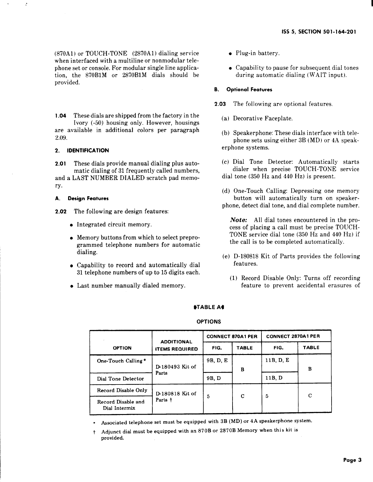
Kit of Parts, D-180493 (Dial Tone Detector
and One-Touch Calling Switch)
Kit of Parts, D-180818 (Record Disable and
Dial Intermix) (see Note 3)
Note 1: Color suffix as follows: Black (-03),
Green (-51), White (-58), and Light Beige (-60).
Note 2: Color suffix as follows: Teak
Woodgrain (-108) or Walnut Woodgrain (-109).
$B2-type is the same as B1-type faceplate ex-
cept woodgrain runs in the opposite direction.
B2-type faceplates are compatible with MET
sets and COM KEY 416 key telephone system.q
Note 3: The D-180818 Kit of Parts can only
be used on dials equipped with an 870B or 2870B
Memory.
Operating Features
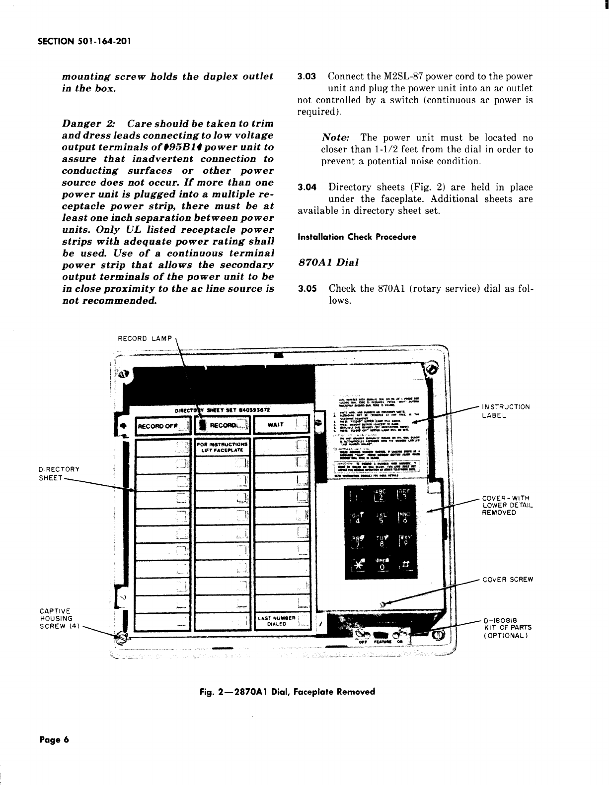
OOperating features (Fig. 1) are as follows.
●Dial.
●32-button array of low force, low travel
nonlocking memory buttons arranged in
three columns. Left and right columns have
eleven buttons, center column has ten but-
tons.
●LAST NUMBER DIALED button located in
lower right corner of memory array, when
momentarily depressed, automatically
redials the last number manually dialed from
the adjunct dial.
●RECORD button (nonlocking), when momen-
tarily depressed, lights the RECORD lamp
*Registered Trademark of American Telephone and Telegraph
Company.
●
●
1SS5, SECTION 501-164-201
and enables the memory circuits to store tele-
phone numbers.
RECORD OFF button (nonlocking), when
momentarily depressed extinguishes the
RECORD lamp, indicating that the dialer is
switched out of the record mode.
WAIT button (nonlocking), when momentar-
ily depressed during recording operation,
enters acode into memory to initiate ahalt
in the automatic dialing sequence [used
where access digit(s) required].
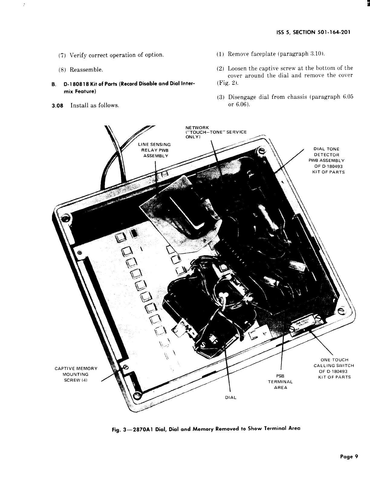
3. INSTALLATION
STANDARD INSTALLATION
3.01
Warning: Do not plug in either battery
or power unit until all connections and
modifications are completed. Take ex-
treme care not to damage the exposed
components, circuit, etc. when the set is
opened.
Connect the adjunct dial to the telephone set
using the D10U~87 or D1OY-5Omounting cord.
Refer to Fig. 6and 7for basic interface connections
and to Tables Dthrough Gfor specific connections.
3.02 The dials are shipped from the factory with
the battery disconnected. After all wiring
changes and modifications have been completed, con-
nect the battery by tilting the adjunct dial up and
inserting the battery plug into the mating jack.
Note: Write date of battery installation on
label provided.
Danger 1: For safety, securely attach
retaining clamp, if used, to ac outlet using
outlet cover screw BEFORE attempting
to install 995B14 power unit. The POwer
unit and any other cord plugged into the
ac outlet should always be unplugged
completely from the outlet BEFORE at-
tempting attach or remove the retaining
clamp. This will prevent the possibility yof
aloosened retainer clamp or metallic
outlet cover making contact with the ac
prongs of the power unit when partially
withdrawn from outlet. Do not use re-
taining clamp on outlets where the cover
Page 5

SECTION 501-164-201
mounting screw holds the duplex outlet
in the box.
Danger 2: Care should be taken to trim
and dress leads connecting to 10wvoltage
output terminals of495B14 power unit to
assure that inadvertent connection to
conducting surfaces or other power
source does not occur. If more than one
power unit is plugged into amultiple re-
ceptacle power strip, there must be at
least one inch separation between power
units. Only UL listed receptacle power
strips with adequate power rating shall
be used. Use of acontinuous terminal
power strip that allows the secondary
output terminals of the power unit to be
in close proximity to the ac line source is
not recommended.
3.03 Connect the M2SL-87 power cord to the power
unit and plug the power unit into an ac outlet
not controlled by aswitch (continuous ac power is
required).
Note: The power unit must be located no
closer than 1-1/2 feet from the dial in order to
prevent apotential noise condition.
3.o4 Directory sheets (Fig. 2) are held in place
under the faceplate. Additional sheets are
available in directory sheet set.
Installation Check Procedure
870A 1Dial
3.05 Check the 870A1 (rotary service) dial as fol-
lows.
RECORD LAMP
...-—
DIRECTORY
‘HEET4
CAPTIVE
HOUSING
SCREW (41 ,r%)
.-
J
-1
.,. --,------
01~,.&lp . . - --
II
t
INSTRUCTION
LABEL
COVER- WITH
LOWER DETAIL
REMOVED
COYER SCREW
.#=’lTl D-18081E3
KIT OF PARTS
A-.
‘a m-w (OPTIONAL)
.. —...-. -—-----—-- ——-—”— -—.- 4
i.. —-. ---- ._.-—. ----
Fig. 2—2870A 1Dial, Faceplate Removed
Page 6

1SS5, SECTION 501-164-201
(1) Check operation of line sensing circuit per the
following tests. (Refer to Part 5for operation. )
In case of failure, refer to Table H(Trouble Analy-
sis).
(a) With telephone handset on-hook, momen-
tarily depress RECORD button. RECORD
lamp should light.
(b) Lift telephone handset off-hook. RECORD
lamp should be extinguished.
(2) Using the telephone set dial, manually dial a
known number to check that the telephone set
operates correctly.
(3) For the adjunct dial, perform dial speed test
as follows.
(a) Obtain dial tone.
(b) Dial code number for dial speed test.
(c) After dial tone is heard again, manually
dial digit O.One of the following audible sig-
nals will indicate how the dial meets the re-
quirements of the test.
(1) Audible ringback: dial speed satisfacto-
ry.
(2) Rapidly interrupted dial tone: dial speed
fast.
(3) Slowly interrupted dial tone: dial speed
slow.
(4) With the telephone handset on-hook, use the
dial on the adjunct to record known telephone
numbers, storing consecutive digits of the num-
bers in sequential memory locations. Fill all mem-
ory locations except LAST NUMBER DIALED
and the location immediately above it [paragraph
5.01 (4) through (7)].
(5) Automatically dial the telephone numbers
stored in Step (4) by momentarily depressing
the memory buttons in the same sequence in which
the digits were recorded. Verify that the digits
thus dialed produce the expected telephone num-
bers.
(6) Go off-hook and use the dial on the adjunct to
record aknown telephone number into mem-
ory location immediately above LAST NUMBER
DIALED location [paragraph 5.01 (4) through (7)].
(7) Momentarily hang up handset and then auto-
matically dial the number recorded in Step (6).
(8) Go off-hook and from the adjunct, manually
dial aknown telephone number.
Note: If apause for second dial tone is re-
quired, dial the access digit(s). After the RE-
CORD lamp relights, depress the WAIT button
then dial the telephone number.
(9) Momentarily hang up handset and then auto-
matically redial the number [dialed in Step
(8)] by depressing the LAST NUMBER DIALED
button.
Note: The dial should stop dialing if it
reaches astored WAIT input. Depress the
LAST NUMBER DIALED button again and the
remaining digits should be dialed.
K
RThe battery and power unit must be
connected aminim urn of five min-
utes before doing Step (10).
(10) Momentarily disconnect the power unit (for
5to 10 seconds). After reconnecting power
unit, momentarily depress memory buttons in
same sequence in which digits were recorded in
Step (4). Verify that the correct telephone number
is dialed.
(11) Dial the appropriate code for ring-back to
test the telephone set ringer.
(12) If equipped with one-touch calling option, (D-
180493 Kit of Parts and speakerphone), and
with set in on-hook condition, depress the memory
button used in Step (6). The speakerphone should
turn on, dial tone should automatically be detect-
ed, and the stored number should be automatically
dialed.
2870A1 Dial
3.06 Check the 2870A1 (TOUCH-TONE service)
dial as follows.
(1) Check operation of the line sensing circuit per
the following tests. (Refer to Part 5for opera-
Page 7

SECTION 501-164-201
tion. )In case of failure, refer to Table I(Trouble
Analysis).
(a) With the telephone handset on-hook, mo-
mentarily depress the RECORD button.
RECORD lamp should light.
(b) Lift telephone handset. RECORD lamp
should be extinguished.
(2) Using the telephone set dial, manually dial a
known number to check that telephone set
operates correctly.
(3) With the telephone handset on-hook, use the
dial on the adjunct to record digits 1through
Oin consecutive memory locations, storing one
digit per memory. Fill all memory locations except
LAST NUMBER DIALED and the memory loca-
tion immediately above it [paragraph 5.01 (4)
through (7)].
(4) Lift handset off-hook and record CO dial test
and ringer circuit number into memory loca-
tion immediately above LAST NUMBER DIALED
location [paragraph 5.01 (4) through (7)]. After
depressing RECORD OFF button, and when dial
test circuit is ready, test dial frequencies by manu-
ally dialing digits 1through Ointo the test circuit.
(5) Momentarily hang up handset and then auto-
matically redial the test circuit number re-
corded in Step (4) by depressing button
immediately above LAST NUMBER DIALED but-
ton and proceed as follows:
(a) Depress LAST NUMBER DIALED button.
Digits 1through Owill be automatically
dialed into test circuit. Verify that correct sig-
nal is returned from test circuit.
(b) Momentarily depress the memory buttons
used in Step (3) in the same sequence in
which the digits were recorded. Verify that the
correct signal is returned from the test circuit.
K
RThe battery and power unit must be
connected aminim urn of five min-
utes before doing Step (c).
(c) Disconnect the power unit from the ac out-
let. With the handset off-hook and using the
telephone set dial, manually dial aknown num-
ber to check that the telephone set operates cor-
rectly.
Note: With ac power removed, the adjunct
dial is inoperative.
(6) Reconnect the power unit, momentarily de-
press the LAST NUMBER DIALED button.
Verify that the number dialed is the same as that
recorded in Step (4).
(7) If equipped with one-touch calling option (D-
180493 Kit of Parts and speakerphone), and
with the telephone set in on-hook condition, de-
press the memory button previously used in Step
(4). The speakerphone should turn on, dial tone
should automatically be detected, and the stored
number should be automatically dialed.
OPTIONAL APPARATUS INSTALLATION
A. D-180493 Kit of Parts (Dial Tone Detector and One-
Touch Calling Switch)
3.07
(1)
(2)
Install as follows.
Remove the housing (paragraph 3.11)and ac-
cess PSB terminal board (paragraph 3.09).
Insert the dial tone detector board assembly
from the back of the dial, such that the two
tabs on the board assembly fit into the slots in the
chassis (Fig. 3).
(3) Insert the self-threading screw through the
side of the chassis to secure the board in posi-
tion.
(4) Mount the one-touch calling switch below the
dial with the two screws provided.
Note: If the switch for D-180818 Kit of Parts
is already present, the one-touc!l calling switch
cannot be installed. The terminals on the PSB
to which the one-touch switch should have been
connected (Table B) shall be strapped together.
(The one-touch calling option can no longer be
disabled by the subscriber. )
(5) Connect per Table B.
(6) Break off the detail at the bottom of the cover
(Fig. 4) and trim edge as required.
Page 8

1SS5, SECTION 501-164-201
(7) Verify correct operation of option. (1) Remove faceplate (paragraph 3.10)
(8) Reassemble. (2) Loosen the captive screw at the bottom of the
cover around the dial and remove the cover
B. D-1808 18 Kit of Ports (Record Disable and Dial lnter- (Fig. 2).
mix Feature) (3) Disengage dial from chassis (paragraph 6.05
3.08 Install as follows. or 6.06).
Fig. 3—2870A1 Dial, Dial and Memory Removed to Show Terminal Area
Page 9

SECTION 501-164-201
Mh$l L
;~s FOR
809!8 KIT
PARTS
=MEMORY
“AI L-
‘0 R
SWITCHES
Fig. 4—2870A 1Dial, Internal View
(4) Loosen the four captive Memory mounting 18019;1 Kit of Parts) is already present it shall
screws (Fig. 3). be removed and the PSB terminals to \vhich it
~vas connected (Table B) shall be strapped to-
(5) Rotate the left edge of the Memory upward as gether. (The one-touch calling option can no
shown in Fig. 4longer be disabled by the subscriber. )
Note: If existing memory is 8’70A or 2870A, it
must be replaced with 870B or 28’70B, respec- (7)
tively. Carefully repack existing memory to en-
sure recovery.
(8)
(6) Mount switch below dial with the two scre;vs
pro~’ided,
Connect switch lead connectors to terminal
posts on memory board per T:ihle C.
Set FE,ITURE s~vitch to OFF position and
v(’rify that ~lia] operates in normal manner.
Note: If the one-touch calling s~vitch (D- ..Nomh’rs tan be recorded into memory
Page 10

1SS5, SECTION 501-164-201
TABLE B
CONNECTIONSFOR DIAL TONE DETECTOR ONLY AND ONE-TOUCH CALLING (NOTE)
ON 870A1 DIAL ON 2870A1 DIAL
LEAD CONNECT TO PSB CONNECT TO PSB
APPARATUS REMOVE TERM. FOR REMOVE TERM. FOR
FROM DIAL TONE FROM
PSB ONE-TOUCH PsB DIAL TONE
DESIG COLOR DETECTOR DETECTOR ONE-TOUCH
ONLYt CALLING ONLYt CALLING
Strap BK 11 **
870A1 or 19 **
2870A1 Dial IStraD IBK 1206 I-I*126 /*I*]
Adjunct
D-180493
Kit of
Parts
.
Strap BK 23 * * 295 —*
Input G-R 22 16 16
PB O-BK 7 7 9 9
Input G-R 16 16 17 17
DT o-Y 11 11 19 19
Dial ‘K Y-G *13 *33
Tone VDD R-O 17 17 21 21
‘etec- SPR Y-BL *18 *
tor 2’7
DR Y-o 19 19 24 24
conl BK-O 20 20 29 29
SPO G-Y *21 *34
PL O-R 22 22 25 25
DTT BL-Y 23 23 26 26 “
Switch S1 s*15 *28
+
+S2 s*20 *29
Note: For connection of D1OU-87 or D1OY-5O cord at telephone set end, refer to Tables Dthrough G
*Insulate and store.
~When dial tone detector only is provided, first dial tone may or may not be precise (350 Hz and 440 Hz) but all sub-
sequent dial tones must be precise.
f. Switch is required for one-touch calling option only (dial tone detector and speakerphone) and all dial tones must
be precise (350 Hz and 440 Hz).
$Do not remove from PSB when dial tone detector only is provided.
●Numbers can be deleted or changed in memo- (2)
ry
.Numbers can be automatically dialed. (3)
No telephone numbers can be recorded,
deleted, or changed in memory.
LAST NUMBER DIALED feature still
operative.
(9) Set FEATURE switch to ON position and ver-
ify feature provided. (b) For record disable and dial intermix fea-
tures.
(a) For record disable only feature. (1) Record lamp will not light when RE-
(1) Record lamp will not light when RE- CORD button is depressed.
CORD button is depressed.
Page 11

SECTION 501-164-201
(2) No telephone numbers can be recorded,
deleted, or changed in memory.
(3) Manually and automatically dialed digits
may be intermixed. (Depression of RE-
CORD OFF button not required. )
(4) LAST NUMBER DIALED feature dis-
abled.
(10) Reassemble adjunct dial.
COMPONENT LOCATION AND ACCESS INFORMATION
Danger: When it is necessary to access
component parts of terminal areas, ac
power must be disconnected.
A. Power Supply Board (PSB) Terminals
3.09
(1)
(2)
(3)
(4)
(5)
To access the terminal field on the power sup-
ply board, proceed as follows.
Disconnect power unit from ac outlet.
Remove the faceplate (paragraph 3.10).
Loosen the captive cover screw at the bottom
of the cover around the dial (Fig. 2).
Remove the cover.
Loosen the two captive dial mounting screws.
Note: On units with metal dial brackets, the
screws will have to be removed.
Fig. 5—2870A 1Dial, Connection of D-180818 Kit of Parts, Record Disable Feature
Only
Page 12

I
1SS5, SECTION 501-164-201
TABLE C
CONNECTIONS FOR D-180818 KIT OF PARTS
ID-KIT ITERMINAL POSTS FOR SWITCH
SWITCH LEADS LEAD CONNECTORS I
COLOR RECORD RECORD DISABLE AND DIAL
DESIG (NOTE l) DISABLE
ONLY INTERMIX (NOTE 2)
WDc BKf’ *1
VDD R22
RCD BK 33
Notes:
1. There are connectors attached to the switch leads, a
single pin connector with a(BK) lead and adouble pin
connector with a(R) and (BK) lead.
2. When this option is provided, the LAST NUMBER
DIALED (LND) feature is disabled and the 32nd
memory may be used just as any other memory.
*Insulate and store.
~Single pin connector.
(6) On the 870A1 dial, place the 8-type dial aside
to gain access to some of the PSB terminals.
On the 2870A1 dial, carefully disengage the con-
nector of the 35-type dial and rotate the dial onto
the memory button field (Fig. 3).
(7) Remove the two mounting screws for the Line
Sensing Relay Board and place the board as-
sembly aside to access the remaining terminals on
the PSB.
(8) To reassemble, reverse this procedure.
B. Faceplate Removal
3.10 To remove, proceed as follows.
(a) Remove 870B1, 870B2, 2870B1, or 2870B2 face-
plate as follows.
(1) The B1 ~or B24 faceplate is held in place by
aspring clip attached to the 870A1U upper
housing. To disengage the faceplate, lift up on
the tab which protrudes from the center of the
back edge of the faceplate.
(b) Remove 870A2
as follows. MD or 2870A2 (MD) faceplate
(1) For those adjunct dials equipped with a
870A2-87 or 2870A2-87 faceplate, it is held
in place by two snaps bonded to the faceplate
and aligned to fit holes in the chassis. To re-
move the faceplate, grasp it. by any convenient
edge and lift off.
Note: The B1 or $B24 faceplate is not adirect
replacement for the A.2 faceplate described
since an 870A1U upper housing is also required
(paragraph 6.08).
c. Housing Removal
3.11 To remove, proceed as follows.
(a) Remove lower housing as follows.
(1) Remove the faceplate (paragraph 3.10).
(2) Disengage the captive housing screws (Fig.
2). One is located in each of the four corners
of the chassis.
Page 13

SECTION 501-164-201
(3) Separate the housing from the adjunct dial
base while feeding the two cords through
hole in bottom of housing.
(4) Before replacing the housing, lift the ad-
junct to check that the shoulders of the bat-
tery jack are against the two chassis tabs.
Misalignment may cause the bottom of the
housing to bow.
(b) Remove upper housing as follows.
(1) Remove the faceplate (paragraph 3.10).
(2) Disengage the captive housing screws. One
is located in each of the four corners of the
upper housing (Fig. 2).
(3) Pull the upper housing away from the chas-
sis as each housing screw is backed out. This
will separate the upper housing from the chas-
sis.
Note: If the upper housing is being replaced,
it will be necessary to remove the housing
screws.
(4) To reassemble, reverse procedure.
4. CONNECTIONS
4.o1 Typical interface connections for the basic
870A1 and 2870A1 dials are shown in Fig. 6.
4.02 Typical interface connections for the 870A1
and 2870A1 dials to provide the one-touch call-
ing feature are shown in Fig. 7.
4.o3 Connections for the adjunct dial to aselected
variety of telephone sets and consoles may be
found in the following tables:
●
●
●
●
Table D–870A1 Dial Connections to Tele-
phones
Table E–2870A1 Dial Connections to Tele-
phones
Table F–870A1 Dial Connections to Con-
soles
Table G–2870A1 Dial Connections to Con-
soles.
4.04 Refer to Table Afor connection references for
all options.
Page 14
4.o5 Adjunct dial connections are shown in Fig. 9
for the 870A1 dial and in Fig. 11 for the
2870A1 dial.
4.06 Partial functional schematics are shown in
Fig. 10 for the 870A1 dial and in Fig. 12 for the
2870A1 dial.
5. OPERATION
A. Record aNumber Into Memory
Note: If equipped with the D-180818 Kit of
Parts, switch must be in the OFF position.
5.01 To record, only the dial of the adjunct may be
used. Digits manually dialed on the associated
telephone set will not be recorded into memory.
(1) Remove the faceplate (paragraph 3.10).
(2) Write or type the desired name and telephone
number for aselected memory button on the
associated position of the directory sheet.
(3) Replace the directory sheet and faceplate.
(4) Depress the RECORD button. The RECORD
lamp will light. (A number can be called and
recorded simultaneously by lifting handset before
depressing the RECORD button.)
(5) Depress the specific memory button adjacent
to the desired telephone number listed on the
directory sheet.
(6) Using the adjunct dial, manually dial the de-
sired telephone number.
Note: If an access code and pause for second
dial tone is required, perform Steps (a) through
(c).
(a) Dial the access digit(s).
(b) After the RECORD lamp lights, push the
WAIT button. (The WAIT entry counts as
one digit. )
(c) Using the adjunct dial, manually dial the
telephone number.
Note: Anumber up to 15 digits in length may
be recorded. The RECORD lamp will go out

B<
momentarily as each digit is dialed. If exactly
15 digits are recorded, the RECORD lamp will
go out and stay out, indicating that the dialer
has been reset. If amemory button has not been
depressed, the RECORD lamp will go out when
the first digit is dialed and recording operation
will be voided.
(7) Depress the RECORD OFF button if less than
15 digits are recorded. The RECORD lamp wi!l
go out. The dialer will be reset. The number is now
stored in the selected memory. The dialer will also
be reset by aswitchhook or speakerphone opera-
tion.
Change aNumber In Memory
lVote: If equipped with the D-180818 Kit of
Parts, switch must be in the OFF position.
5.02 Whenever anew number is recorded in apre-
viously used memory position, it will automat-
ically replace the previously stored number.
c. Delete aNumber From Memory
Note: If equipped with the D-180818 Kit of
Parts, switch must be in the OFF position.
5.03
(1)
(2)
(3)
To delete anumber, proceed as follows.
Depress the RECORD button.
Depress the memory button corresponding to
the name and number to be deleted.
Depress the RECORD OFF button.
D. Automatically Dial aNumber From Memory
5.o4 To automatically dial anumber, proceed as
follows.
(1) Go off-hook on the telephone set, listen for
dial tone, and depress the desired memory but-
ton. If WAIT input has been recorded, automatic
dialing will stop. When second dial tone is heard,
depress memory button again to complete auto-
matic dialing.
(2) If the adjunct dial is equipped with the dial
tone detector only, go off-hook, listen for dial
tone, and depress the memory button.
(3) If the adjunct dial is wired to provide the one-
touch calling feature (telephone set is
E.
I
1SS5, SECTION 501-164-201
equipped with speakerphone, and adjunct dial
equipped with dial tone detector), simply depress
the memory button.
LAST NUMBER DIALED Feature
5!05
Note: If equipped with the D-180818 Kit of
Parts, and dial intermix feature is provided,
switch must be in the OFF position.
The adjunct dial automatically records into
the LAST NUMBER DIALED position (Fig. 1)
any number called using the dial of the adjunct. Each
number in the LAST ,NUMBER DIALED position is
automatically replaced by the next number manually
dialed. Although the unit is recording, the RECORD
lamp does not light at any time during this operation.
5.06 Operation of LAST NUMBER DIALED fea-
ture is as follows.
(a) If no access digit(s) are required, proceed as
follows
(1) Go off-hook on the telephone set
(2) Listen for dial tone
(3) Manually dial telephone number using the
adjunct dial
(4) To redial same number automatically, go
off-hook on telephone set, listen for dial
tone, and depress LAST NUMBER DIALED
button.
(b) If an access code and pause for second dial
tone is required, proceed as follows:
(1)
(2)
(3)
(4)
(5)
(6)
Go off-hook on the telephone set
Listen for dial tone
Dial access digit(s) using adjunct dial
After second dial tone is heard depress
WAIT button
Manaully dial telephone number using ad-
junct dial
To redial same number automatically-, go
off-hook, listen for dial tone, and depress
Page 15

SECTION 501-164-201
LAST NUMBER DIALED button. When second
dial tone is heard, depress LAST NUMBER
DIALED button again to complete automatic
dialing.
F. End-to-End Signaling (2870A 1Only)
s.07 For end-to-end signaling (such as data trans-
mission), the 2870A1 dial has the capability to
intermix manual and automatic dialing.
5.08 If the one-touch calling option is provided, the
initial number must be dialed automatically
(even if the one-touch switch is in the OFF position).
This allows the dial tone detector to complete its
function. Additional numbers may then be dialed
automatically or manually if desired.
(a) Standard Operation: If at any time, dig-
it(s) are keyed manually using the 2870A1
dial, the RECORD OFF button must be depressed
before additional digits can be dialed automati-
cally from memory. (The RECORD lamp will not
light at any time but depressing the RECORD
OFF button will remove the dial from the LAST
NUMBER DIALED mode to allow additional auto-
matic dialing. )
(b) 9Dial Intermix Mode (with D-180818
Kit ofParts): 4Manually and automatically
dialed digits may be intermixed as desired when
the FEATURE switch is in the ON position.
Note: In this mode, the RECORD button and
the LAST NUMBER DIALED feature are inop-
erative.
6. MAINTENANCE
6.01 In case of power failure, the adjunct dial is
inoperative. The battery retains the number
associated with each of the memory buttons for at
least 24 hours. If power loss exceeds 24 hours, the
numbers may have to be rerecorded.
A. Trouble Analysis
6.02 When trouble is encountered, the subsequent
procedure should be followed.
(1) Confirm improper operation either as abasic
dial or as an automatic dialer (Part 5).
(3) Refer to Trouble Analysis Table H(8701
Table I(2870A1).
(4) If removal of adjunct dial is required, pr
as follows.
(a) Disconnect power unit from ac outle
unplug battery.
(b) Disconnect adjunct dial.
Warning: Failure to restrain PIU$
result in plug damage requiring ba
replacement t.
(c) Place battery plug sideways into hc
slot below battery pack and tape into
B. Battery
6.03 The battery has an expected life of at
years. It can be replaced without loss of:
numbers provided that commercial ac power ~
dial is continuously maintained. To replace th
tery, proceed as follows:
(1) Tilt the front of the dial adjunct up
(2) Unplug the battery
(3) Loosen captive screw on the battery SUI
(4) Remove battery support
(5) Remove battery
(6) Install and check new battery (paragraph 3
or 3.06).
C. Memory
6.04 The memory may be replaced in the foil
manner.
(1) Disconnect power unit from ac outle
unplug battery.
Note: Removal of the memory or ac an
tery power results in loss of stored numt
(2) Remove the faceplate (paragraph 3.10).
(2) Check connections. (3) Loosen the four captive memory mol
screws (Fig. 3).
Pcrge 16

,
1SS5, SECTION 501-164-201
(4) Rotate the left edge of the memory upward as
shown in Fig. 4. (2) Remove faceplate (paragraph 3.10).
(5) Disengage the connector(s) by pulling them
perpendicular to the printed wiring board. (3) Loosen the captive screw at bottom of the
cover around the dial and remove the cover.
(6) Replace the memory by engaging the dial con-
nector (2870A1 only) first. The connector(s)
are keyed, one position is filled and should fit over
the vacant position in the row of pins. The flat
power supply cable should not be twisted.
(4) Disengage the two dial mounting screws.
lVote: On early units, with metal dial brack-
ets, the screws will have to be removed.
(5) Disengage the four captive memory mounting
screws (Fig. 3).
(7) Reassemble dial.
(8) Reconnect battery and power unit. (6) Gently raise the memory to aposition that
permits access to the dial connector.
(9) Test per paragraph 3.05 or 3.06 as required.
(7) Disengage the dial connector by carefully pull-
ing on it perpendicular to the printed wiring
board.
(10) Reprogram memory (see Part 5).
D. Dial
(8) Disengage the second dial connector from the
power supply printed wiring board.
6.05 Replace rotary dial as follows.
(1) Disconnect power unit from ac outlet and
unplug battery. (9) Lift the dial out.
Note: Removal of ac and battery power re-
sults in loss of stored numbers. (10) To replace with anew dial, reverse the previ-
ous steps. The connectors are keyed to orient
them relative to the pins. Observe the correct ori-
entation and do not force the connection.
(2) Remove faceplate (paragraph 3.10).
(3) Loosen the captive screw at bottom of the
cover around the dial and remove the cover. (11) Reconnect battery and power unit.
(12) Reprogram memory, see Part 5.
(4) Remove the two dial mounting screws and set
dial aside. E. line Sensing Relay Printed Wiring 8oard Assembly
6.07 RepIace as follows.
(5) Remove dial leads from terminals on PSB.
(1) Disconnect power unit from ac outlet and
unplug battery.
(6) Remove dial.
(7) Reverse procedure to replace dial. Note: Removal of ac and battery power re-
sults in the loss of stored numbers.(8) Reconnect battery and power unit.
(9) Reprogram memory (see Part 5). (2) Remove faceplate (paragraph 3.10).
6.06 Replace TOUCH-TONE* telephone dial as fol-
lows. (3) Loosen the captive screw at the bottom of the
cover around the dial and remove the cover.
(4) Remove the two dial mounting screws (870A1)
or disengage (2870A1).
(1) Disconnect power unit from ac outlet and
unplug battery.
Note: Removal of ac and battery power re-
sults in loss of stored numbers.
*Trademark of American Telephone and Telegraph Company.
(5) Place the dial aside to gain access to the PSB
terminals.
Page 17/18

1SS5, SECTION 501-164-201
(6) Remove the two mounting screws for the Line
Sensing Relay Board and move the board as-
sembly to one side.
(7) Disconnect the leads of the Line Sensing Relay
Board from associated terminals on the PSB,
and remove the board assembly.
(8) Connect the leads of the replacement Line
Sensing Relay Board to the appropriate termi-
nals on the PSB (Fig. 9B and 9C for the 870A1 dial
or Fig. llB and llC for the 2870A1 dial).
(9) Reassemble adjunct dial.
(10) Reconnect battery and power unit.
(11)Reprogram memory, see Part 5.
F. Faceplate (conversion from 870A2 or 2870A2 to
870B1 or 287061)
6.08 Replace an 870A2-87 or 2870.42-87 faceplate
with an 870B1-87 or 2870B1-87 faceplate as
follows.
(1) Remove the A2 faceplate by lifting up on any
of its edges.
(2) Remove the four captive housing screws (Fig.
2) from the chassis.
(3) Use the four housing screws to mount the
870A1U upper housing to the chassis and
870ADJ housing. The three parts should be held
tightly together as the screws are driven.
(4) Place the two tabs located along the lower
edge of the B1 faceplate in the notches in the
lower side of the 870A1U upper housing.
(5) Lower the faceplate to rest on the memory.
The spring clip located in the center of the
upper side of the upper housing should retain the
faceplate.
Page 19

SECTION 501-164-201
TABLE D
CONNECTIONS FOR 870A1 DIAL TO TELEPHONE SET
COMMON TIP PATH COMMON RING PATH
TEL SET
LEAD COLOR REMOVE FROM CONNECT TO$$ LEAD COLOR REMOVE FROM CONNECT TOqq
565HK, HKM GNet. FSpare 1G, G-V 9Spare 2
564HL ,HLM GNet. FSpare 1G9Spare 2
630DA,
DAM (2) GNet. FSpare 1G\$$ 13 Spare 2
631DA,
631DAM (2) GNet. FSpare 1G$$!i 13 Spare 2
634DA, DAM W-BL Net, FSpare 1BL-W$$$ 13 Spare 2
635DA, DAM W-BL Net. FSpare 1BL-W$$$ 13 Spare 2
636CA, CAM (2) GNet. FSpare 1W-BL 13 Spare 2
637DA, DAM (2) GNet. FSpare 1W-BL 13 Spare 2
830CMT Gtt 8Spare 1R6Spare 2
830CMt G16 Spare 1R6Spare 2
830CM$ GNet. FSpare 1R6Spare 2
830DMt,+ Gtt 8Spare 1R3Spare 2
830DM$ GNet. FSpare 1R3Spare 2
831CMt (2) Gtt 8Spare 1(2) R6Spare 2
831CM~ (2) G16 Spare 1(2) R6Spare 2
831CM$ (’2)GNet. FSpare 1(2) R6Spare 2
831DMt,+,$ (2) Gtt 8Spare 1G6Spare 2
WI DM!j,!f (2) GNet. FSpare 1G6Spare 2
832-Type~ G22 Spare 1R4Spare 2
833-Type~ (2) GZSpare 1(2) R4Spare 2
851B
851BT GNet. FSpare 1R13
851BM Spare 2
851CM G2
t*** Spare 1R13 Spare 2
852A
852AM G4ttt Spare 1R1Spare 2
870A1M W-BL TB1 8TB1 15 13L-W TB1 4TBI 16
870A2M GTB1 8TB1 15 RTB1 4TB1 16
870AI Dial~$ w-o 26 27 o-w 9Spare 1
872A1M GTB1 8TB1 15 RPSB 9Net. G
Page 20

1SS5, SECTION 501-164-201
TABLE D(Contd)
CONNECTIONS FOR 870A1 DIAL TO TELEPHONE SET
D1OU-87 CORD (FROM ADJUNCT DIAL)
STANDARD FUNCTIONS ISPEAKERPHONE/ONE-TOUCH
I11 IT1 ILRIRI IMI]M2 ILK ISPO
Iw-al w-o BL-W o-w BR-W W-BR G-w IW-G
Spare tNet. F9Spare 2
Spare 1Net. F9Spare 2
Spare 1Net. F13 Spare 2
Spare 1Net. FSpare 213
Spare 1 8 Spare 2 6
Spare 1 16 Spare 26
Spare 1Net. FSpare 26
Spare 18Spare 23
Spare 1Net. FSpare 2 3
Spare 18Spare 26
Spare 1 16 Spare 26
Spare 1Net, FSpare 26
Spare 1 8 6Spare 2
Spare 1Net, F6Spare 2
Spare 1 22 Spare 24
Spare 122 Spare 24
Spare 1Net. FSpare 213
Net. RNet. GN Net. L1
Net. RNet. GN *
Net. RNet. GN 4
Net. RNet. GN 4
Net. RNet. GN 4
Net. RNet. GN 4
Net. RNet. GN *
Net. RNet, GN *
Net. RNet. GN 29
Net. RNet. GN 29
Net. RNet. GN 29
Net. RNet. GN 29
Net. RNet. GN 29
.Net. RNet. GN 29
Net. RNet. GN 29
Net. RNet. GN 29
Net. RNet. GN 29
Net. RNet. GN 29
Net. RNet. GN 29
Net. RNet. GN 29
Net. RNet. GN Net. L1
See
Fig. 8
Spare 1 2*** Spare 213 Net. RNet. GN 20
Spare 1.Itt’t Spare 21Net. RNet. GN 10
I!1I1I1
T13115 TB1 8TB1 16 TB1 4Net. RNet. GN \PSB 27 PSB 21
ITB1 15 ]TB1 8ITB1 16 ITB1 4INet. RINet. GN IPSB 27 IPSB 21
PSB ’26 PSB 27 PSB 9Spare 1PSB 1PSB 8PSB 13 PSB 21
TB1 15 TB1 8Net. GPSB 9Net. RNet. GN PSB 13 PSB 21
a
P3 P4
s-w w-s
8‘7
**
914
914
14 9
14 9
* *
* *
30 24
30 24
30 24
30 24
30 24
.30 24
30 24
30 24
30 24
30 24
30 24
30 24
=H
PSB 3PSB 6
PSB 3PSB 6
PSB 3PSB 6
PSB 3PSB 6
Page 21
This manual suits for next models
1
Table of contents
Other AT&T Telephone manuals

AT&T
AT&T 1070 User manual

AT&T
AT&T 950 User manual

AT&T
AT&T 1855 - AT&T Corded Phone User manual

AT&T
AT&T Aastra 6731i User manual

AT&T
AT&T SPIRIT 1224 Controller User manual

AT&T
AT&T MS2015 User manual

AT&T
AT&T 874 User manual

AT&T
AT&T U-verse TV User manual

AT&T
AT&T CL4939 User manual

AT&T
AT&T Synapse SB67020 User manual