AT&T MDW 9010 Quick start guide

AT&T
TransTalk™ 9000
Digital Wireless System
MDW 9010 Wireless Telephone
Installation and Use

Copyright © 1996 AT&T
All Rights Reserved
Printed in U.S.A.
AT&T 503-801-141
Comcode 107723710
Issue 1
January 1996
Notice
Every effort was made to ensure that the information in this booklet was complete and
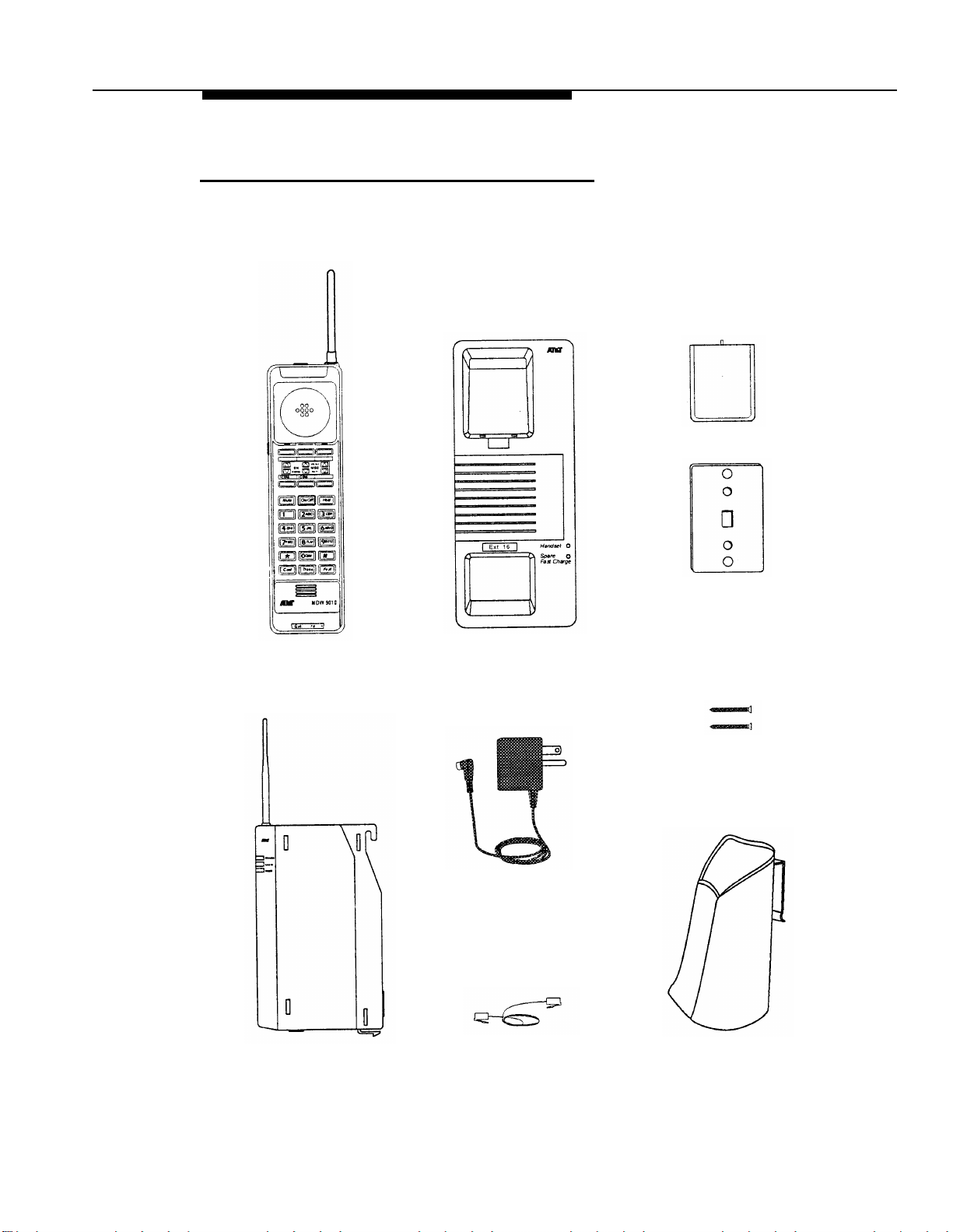
accurate at the time of printing. However, information is subject to change. The pictures in
this booklet are for illustrative purposes only; your actual hardware may look slightly
different.
Federal Communications Commission (FCC) and Industry Canada (IC) Information
For details, see Appendix B.
Security
Toll fraud, the unauthorized use of your telecommunications system by an unauthorized
party (for example, persons other than your company’s employees, agents, subcontrac-
tors, or persons working on your company’s behalf) can result in substantial additional
charges for your telecommunications services. You are responsible for the security of your
system. There may be a risk of toll fraud associated with your telecommunications system.
You are responsible for programming and configuring your equipment to prevent unautho-
rized use. Your system administrator should read all documents provided with this product
to fully understand the features that can introduce the risk of toll fraud and the steps that
can be taken to reduce that risk. AT&T does not warrant that this product is immune from
or will prevent unauthorized use of common-carrier telecommunication services or facilities
accessed through or connected to it. AT&T will not be responsible for any charges that
result from such unauthorized use.
Trademarks
TransTalk is a trademark of AT&T and PARTNER, MERLIN, MERLIN LEGEND, DEFINITY
and SYSTIMAX are registered trademarks of AT&T. Supra is a registered trademark of
Plantronics, Inc.
Warranty
AT&T provides a limited warranty for this product; see Appendix A.
Ordering Information
The order number for this booklet is 503-801-141. The order number for the MDW 9010
Wireless Telephone Quick Reference is 503-801-142. To order additional copies of these
reference materials, call 1 800 457-1235 or 1 317 361-5353. To order parts and accesso-
ries, see “Ordering Replacement & Optional Parts” in Chapter 4.
Customer Support
In the continental U.S., call 1 800 628-2888 if you need assistance when using your
wireless phone with a PARTNER, MERLIN, or MERLIN LEGEND system. Consultation
charges may apply. For all other systems, follow the procedure you normally use to get
support for your communications system.
Outside the continental U.S., contact your AT&T Representative or local Authorized
Dealer.

Contents
1
Introduction
1-1
■
About the MDW 9010
1-1
Privacy Information
1-2
■
Parts List
1-3
■Additional Parts
1-4
2
Installing the MDW 9010
■Important Safety Instructions
Additional Safety Instructions for Installation Personnel
■Radio Modules and Carriers
Key Components
Positioning a Single Radio Module or Carrier(s)
Installing a Single Radio Module
Setting the Power Level
Setting the Control/Expansion DIP Switch
Installing a Single Carrier on a Shelf or Desk
Installing a Single Carrier on a Wall
Installing Multiple Carriers
Installation Self-Test
■Battery Charger
Positioning the Battery Charger
Installing the Battery Charger
Inserting a Battery Pack Into the Fast Charge
Compartment
Removing a Battery Pack from the Fast Charge
Compartment
■Handset
Inserting and Removing the Handset’s Battery Pack
Testing the Handset: Local Test Mode
Wireless Test Mode
Filling Out Labels
2-1
2-1
2-2
2-4
2-5
2-7
2-9
2-11
2-13
2-14
2-17
2-20
2-25
2-26
2-26
2-26
2-29
2-30
2-31
2-31
2-32
2-32
2-34
i

3
Using the MDW 9010
■
Important Safety Instructions
■The Handset
Handset Controls
Handset Display
Line Status Indicators
Call Alerter
Handset Range Indicators
Using the Carrying Holster
Using a Headset
■The Battery Charger
Low Battery Indicator
Extending Battery Life
3-1
3-1
3-4
3-4
3-5
3-5
3-5
3-6
3-7
3-8
3-10
3-11
3-11
4
Maintaining the MDW 9010
4-1
■Important Safety Instructions 4-1
■Removing a Radio Module from the Carrier 4-4
■Swapping Extensions 4-5
■Ordering Replacement & Optional Parts 4-6
5
Troubleshooting
5-1
■Procedures 5-1
Installation Problems 5-1
Handset Problems 5-2
Battery Problems 5-4
Fast Charger Problems 5-5
Voice Quality Problems 5-6
ii

6
MDW 9010 Compatibility
6-1
■Programming and Call Handling Instructions 6-1
■Entering Station Programming Mode 6-1
■Programming System Features 6-2
PARTNER Systems
6-2
MERLIN Systems
6-3
System 25
6-5
System 75, System 85, and DEFINITY Systems
6-6
A
Warranty and Repair Information
A-1
B
Regulatory Information
B-1
C
Specifications
C-1
IN
Index
IN-1
iii

1
About the MDW 9010
Introduction
Congratulations on the purchase of your new TransTalk™ 9000 Digital Wireless System
MDW 9010 Wireless Telephone. MDW stands for Multi-line Digital Wireless. This product
was designed to AT&T’s high standards for innovation, reliability, and convenience.
The MDW 9010 phone is wireless; the telephone line cord to the phone was eliminated. This
provides flexibility, so that you may not require additional telephone wiring when you move
into a new building, or change the phone’s location in an existing building. The phone can
be located as required. All you need is an electrical outlet, and a test check to make sure
that the handset is in range of its matching radio module.
The phone is portable, so there is no handset cord. This portability lets you move about
your work area or home with freedom, without giving up the features of a corded phone.
The handset communicates through a matching radio module, not the battery charger
where the handset sits for charging. Each handset can be used only with the radio module
packaged with the handset. The handset and the radio module each have the same unique
security code to identify the matching pair. And there is built-in and secure automatic
registration between the handset and radio module, so that your system is ready to use
after powering up.
A carrier (also known as a backplane) is required in order to use multiple wireless phones
within the same zone (area of coverage). Holding up to six radio modules, a carrier
synchronizes radio signals for proper operation of multiple phones, ensuring consistent
voice quality and range. Multiple carriers can be linked to support up to 18 wireless
phones in a single zone; linked carriers are automatically synchronized with each other.
As a special feature, a spare battery pack can be stored in the battery charger, allowing for
extended phone usage. For convenience, a headset can be connected to the phone to allow
hands-free conversation.
Introduction
1-1

This booklet describes MDW 9010 telephone installation. Also included with the phone is
a Telephone Quick Reference card that contains information about displays and controls
on the handset and the battery charger.
After you have installed your MDW 9010 phone and understand the controls and displays,
use the programming and call handling instructions that come with your communications
system; follow the user instructions for the phone type identified below:
For this communications system... Use the instructions for a...
PARTNER® MDW 9000 phone.
MERLIN®, MERLIN Plus, and MERLIN II 5-button phone.
MERLIN LEGEND® 10-button ATL set.
System 25 10-button ATL set.
System 75, System 85, and DEFINITY®* 7303s set.
NOTE:
The MDW 9010 phone is fully compatible with the PARTNER family of communications
systems. For the remaining communications systems, however, you must carefully
note the functional differences between your wireless phone and the phone type
identified in the table, as listed in Chapter 6, “MDW 9010 Compatibility.”
Privacy Information
The MDW 9010 phone is designed to protect the privacy and security of your voice
conversation. The set uses continuously changing radio frequencies and digital encoding
techniques to make it impossible for eavesdropping to occur through the use of commer-
cially available analog radio scanners.
* For DEFINITY G3V3 systems, you can administer the system for the MDW 9000 telephone (rather than a
7303s set) and follow the user’s instructions in the MDW 9000 Wireless Telephone User’s Guide, order
number 555-230-768.
1-2
Introduction

Parts List
Along with this booklet and the Telephone Quick Reference card, the box should contain
the items shown below. If it does not, call for customer support as described on the inside
front cover of this booklet.
Handset
Radio Module
Battery Pack
Wall Mounting
Plate
Battery Charger with
Mounting Base
Philips Head
Wood Screws (2)
Charging Cradle 11-foot (3.4 m)
Power Cord/Standard AC
Adapter
8-foot (2.4 m)
Telephone Line Cord Handset Carrying
Holster
Introduction
1-3

Additional Parts
The following parts may be necessary, depending upon your installation.
Kit of parts (order number D-182866) is required only when a single MDW 9010
phone is installed:
Rubber Feet (4)
Radio Module 11-foot (3.4 m) Philips Head Wall Mounting
Power Cord/AC Adapter Wood Screws (2)
Plate
Required when two or more MDW 9010 phones are installed:
Philips Head
Wood Screws (4)
Expansion Cable 6-foot (1.8 m)
for multiple-carrier installation
Carrier Assembly 25-foot (7.6 m)
Power Cord and Standard AC Adapter
Carrier
1-4
Introduction

Installing the MDW 9010
2
Important Safety Instructions
This booklet contains instructions related to safety labels on the product:
WARNING
indicates the presence of a hazard that can cause severe or fatal
personal injury if the hazard is not avoided.
CAUTION indicates the presence of a hazard that will or can cause minor
personal injury or property damage if not avoided.
Always follow these basic safety precautions when installing this product to reduce risk of
injury from fire or electric shock.
Make sure the radio module, carrier, and battery charger are unplugged
before you install them.
The exclamation point within an equilateral triangle is intended to alert the
user to the presence of important operating and maintenance (servicing)
instructions in the literature accompanying the product.
WARNING:
Risk of Electric Shock
Failure to properly ground this product will result in a risk of electrical shock,
which can cause serious personal injury. This product requires a 3-prong AC
power receptacle for safe operation. You should have your receptacle checked
by a qualified electrician before connecting this equipment.
WARNING:
The rechargeable battery pack contains nickel and cadmium. Do not burn or
puncture the battery pack. Like other batteries of this type, if it is burned or
punctured, it could release toxic material which could cause injury. Do not
dispose of it in household garbage. For information about recycling or proper
disposal, consult your local solid waste (garbage) collection or disposal organi-
zation.
Installing the MDW 9010
2-1

Additional Safety Instructions
for Installation Personnel
■
■
■
■
■
■
■
■
■
■
■
■
■
■
■
Install the product to meet all environmental and electrical requirements listed in
Appendix C.
All wiring that connects to this equipment and becomes part of the building wiring
must be a minimum of CLASS 2 or U.L. Listed Communications cable.
Do not install telephone wiring during a lightning storm.
Do not install telephone jacks in a wet location unless the jack is specifically designed
for wet locations. Never touch uninsulated telephone wires or terminals unless the
telephone line has been disconnected at the network interface.
Use caution when installing or modifying telephone lines.
Install this product securely on a stable surface. Damage may result if the product
falls.
Never place this product near or over a radiator or heat register.
Slots and openings in the housing and the back or bottom are provided for ventilation.
To protect the housing from overheating, these openings must not be blocked or
covered. Therefore, do not place the product on a bed, sofa, rug, or other similar
surface. Also, do not place this product in an enclosed area unless proper ventilation
is provided.
Install this product in a protected location where no one can step on or trip over power
cords and telephone line cords. Do not place objects on the cords that may cause
damage or abrasion.
Do not allow anything to rest on the power cord. Do not locate this product where the
cord will be abused by persons walking on it. Do not overload wall outlets as this can
result in the risk of fire or electric shock. Do not staple or otherwise attach the power
cord to building surfaces.
Use only the Model # PIDB-270 power supply shipped with this product for the battery
charger or radio module.
Use only the Model # SW109 power supply shipped with the carrier.
Use only the correct power source. If you are not sure of the power supply to your
location, consult your local power company.
This product uses a 3-prong plug in continental U.S. locations. Such plugs are de-
signed for your safety. Do not attempt to defeat this purpose. If your wall outlet will not
accept the plug, the outlet should be replaced by an electrician.
Use only the type of battery pack shipped with this product.
2-2
Installing the MDW 9010

AC Outlet Check
Have a qualified electrician check all of the outlets into which the MDW 9010 radio mod-
ules or carriers as well as the communications system switch/control unit will be plugged.
The electrician should check that the hot, neutral, and ground wires are properly con-
nected to the outlet by using a circuit tester.
The outlet can also be tested using a voltmeter by taking the measurements as shown:
120 Volts
Neutral
Phase
Less than
G
120
1 volt
volts
NOTE:
If there is no current to the outlet or the voltages are not correct, the problem should
be corrected by a qualified electrician.
CAUTION:
This equipment is for installation on AT&T PARTNER, PARTNER Plus, PARTNER II,
MERLIN, MERLIN Plus, MERLIN II, MERLIN LEGEND, System 25, System 75, System
85, and DEFINITY communications systems only.
WARNING:
Installation of this equipment for In-Range Out of Building (IROB) conditions
requires the use of protectors. See the documentation that came with your
communications system for more information.
Go to “Radio Modules and Carriers.”
Installing the MDW 9010
2-3

Radio Modules and Carriers
This section explains how to install radio modules and carriers. You should proceed
through this section in the following order:
1. “Key Components”
2.
3.
“Positioning a Single Radio Module or Carrier(s)”
Choose one of the following paths, depending upon which components you are
installing:
■
■
■
If you are installing a single radio module, go to
“Installing a Single Radio Module.”
If you are installing a single carrier, go to
a. “Setting the Power Level.” Then go to either
b.“Installing a Single Carrier on a Shelf or Desk” or
“Installing a Single Carrier on a Wall.”
If you are installing multiple carriers, go to all of the following:
a. “Setting the Power Level” then
b. “Setting the Control/Expansion DIP Switch” then
c.“Installing Multiple Carriers.”
4. “Installation Self-Test”
NOTE:
The illustrations in this chapter depict PARTNER system hardware; your hardware may
differ from these illustrations.
2-4
Installing the MDW 9010

Key Components
Each radio module communicates with a corresponding handset.
Antenna
LEDs
Mounting
Hook
Power Cord
Connector
Card Edge
(Cover not
shown)
Snap Lock
Telephone
Line Cord
Connector
Installing the MDW 9010
2-5

A carrier is required when installing two or more MDW 9010 telephones.
Power DIP Control/Expansion
Switch DIP Switch
Radio
Module
Mounting
Rods
Radio
Module
Mounting
Rods
Wall Mount
Hole
Wall Mount
Hole
Power Cord
Connector
(hidden)
In Jack
Out Jack
Out of Sync LED
Card Edge
Connectors Card Edge
Connectors
Slot
Numbers Slot
Numbers
Wall Mount
Hole
Wall Mount
Hole
Cable Rear
Manager Slot Exit Slots
Using the expansion cable provided with each carrier, you may link up to three carriers.
From
Control Carrier From
Expansion
Carrier #1
To
Expansion
Carrier #1
To
Expansion
Carrier #2
Control
Expansion
Expansion
Carrier Carrier #1
Carrier #2
2-6
Installing the MDW 9010

Positioning a Single Radio Module or Carrier(s)
All of your MDW 9010 handsets and their corresponding radio modules operate within a
single zone of coverage:
The range depends on your particular operating environment. For indoor use, intervening
walls will reduce the phone’s range. Try to stay away from concentrations of structural
metal, such as steel and aluminum, and reinforced concrete.
IMPORTANT:
The MDW 9010 phone has a built-in testing feature that you can use before
installation to help determine proper placement of the radio module. To perform
the test, all you need is an electrical outlet for the radio module and a charged
battery pack in the handset (you do not need a communications system switch/
control unit). Refer to “Wireless Test Mode” later in this chapter for details.
General Positioning Rules
Before you install the radio module or carrier(s), note the following rules regarding location
and use. Failure to follow these rules will result in poor performance of your MDW
9010 phone system.
■Position the radio module or carrier(s) in a central location, relative to the handset(s)
usage area. For convenience, you may want to place the radio module or carrier(s) in
the same room, and on the same wall, as your communications system switch/control
unit. If your switch/control unit is located in a remote location, you may have to run a
telephone line cord from your switch/control unit to the centrally positioned radio module
or carrier(s). The maximum distance is 1,000 feet (333 m) of 26-gauge cable.
Installing the MDW 9010
2-7

■
■
■
■
■
■
At least
6 feet (2 m)
is required between the radio module or carrier(s) and the communi-
cations system switch/control unit.
The radio module or carrier(s) should be placed high on the wall for optimum voice
quality and range. Allow at least 6 inches (15.2 cm) of space between the top of the
antenna on the radio modules and the ceiling.
The radio module or carrier(s) should never be installed above a drop, suspended
level ceiling.
The radio module or carrier(s) should not be within 6 feet (2 m) of equipment with
microprocessors such as answering machines, personal computers, and fax
machines; electromagnetic equipment such as electric motors; or electrical main
power feeds, junction boxes, circuit-breaker panels, fuse boxes, or 220-volt
power lines.
The radio module or carrier(s) should not share the same power line as equipment with
microprocessors such as answering machines, personal computers, and fax machines;
or electromagnetic equipment such as electric motors.
If your communications system uses an uninterruptable power supply, such as a backup
generator, be sure to connect the radio module or carrier(s) to that power supply.
Additional rules for a single radio module only:
■Installing a single radio module on a shelf or desk is not recommended, because it
greatly reduces the range and quality of the transmission.
■Install a single radio module within 3 feet (1 m) of either side of, and within 6 to 8 feet
(2 to 2.6 m) above, a properly grounded 3-prong electrical outlet that is not controlled
by an on/off switch.
■You can install a single radio module in a remote location using a telephone line cord
to connect the radio module to the communications system switch/control unit. IROBs
must be used for out-of-building installations.
Additional rules for installing one or more carriers:
■Install carrier(s) within 15 feet (5 m) of either side of, and within 6 to 8 feet (2 to 2.6 m)
above, a properly grounded 3-prong electrical outlet that is not controlled by an on/off
switch.
■Choose a location where handset users will not approach the carrier(s) within a radius
of 6 feet (1.8 m) for 1 or 2 carriers or 10 feet (3.1 m) for 3 carriers.
■Carrier(s) cannot be exposed outdoors to the elements.
■When installing multiple carriers:
–Install multiple carriers 1 foot (0.3 m) optimally to 4 feet (1.2 m) apart.
–Install multiple carriers on the same horizontal axis (do not install one carrier
higher or lower than another).
–Install the control carrier as the leftmost carrier, using only the expansion cables
provided.
–There must always be a radio module in slot 6 of the control carrier.
Go to one of the following sections:
■If Installing one MDW 9010 phone, go to “Installing a Single Radio
Module.”
■Otherwise, go to “Setting the Power Level.”
2-8
Installing the MDW 9010

Installing a Single Radio Module
■
■
Install high on wall, leaving at least 6 inches (15.2 cm) between antenna and ceiling
See “Key Components” earlier in this chapter for additional picture detail
1Check to make sure the radio module’s power
cord is unplugged from the wall outlet before
continuing.
2Detach the rubber feet. Apply them to marked
areas on the underside of the radio module.
3Place the wall mounting plate against the wall.
Choose a location backed by a wooden stud (if
unavailable, use toggle bolts instead of the supplied
wood screws). Lightly tap a nail into the wall to start
holes. Then screw the plate flush to the wall. Place
the radio module over the plate, then slide it down-
ward to lock it into place. (Note: Do not remove the
plastic cap covering the radio module’s card edge.) Screw
Holes
4Insert one end of the telephone line cord into
an extension jack or terminal/station connector
on your communications system switch/control unit
(refer to your communications system manual for the
proper location).
Installing the MDW 9010
2-9

5Insert the radio module’s power cord into the
side of the radio module. Insert the other end of
the telephone line cord into the bottom of the radio
module.
6
Plug the power cord/AC adapter into a properly
grounded 3-prong wall outlet that is not controlled
by an on/off switch.
CAUTION: Never connect or disconnect
the telephone line cord while the radio
module is plugged into the wall outlet.
Go to “Installation Self-Test.”
2-10
Installing the MDW 9010

Setting the Power Level
If you are installing one or more carriers in a strip mall, high-rise office building, or similar
environment, the MDW 9010 phones may interfere with other wireless products in use.
■If this is the case, you may need to adjust the range of the carriers to prevent
overlapping with the other wireless products; follow the instructions in this section.
■If this is not the case, skip this section and go to “Setting the Control/Expansion DIP
Switch.”
You may adjust the range by setting each carrier’s power DIP switch, located in slot 2:
Power
DIP Switch
Slot 2
Installing the MDW 9010
2-11
Other manuals for MDW 9010
1
Table of contents
Other AT&T Telephone manuals

AT&T
AT&T SPIRIT 2448 Expansion Unit Parts list manual

AT&T
AT&T Plus User manual

AT&T
AT&T CL2909 User manual

AT&T
AT&T CRL32102 User manual

AT&T
AT&T Four-Line Intercom Speakerphone 974 User manual

AT&T
AT&T CL84107 User manual

AT&T
AT&T U-verse TV User manual

AT&T
AT&T TL92220 User manual

AT&T
AT&T SynJ SB67118 User manual

AT&T
AT&T U-verse TV User manual

AT&T
AT&T 831 Series User manual

AT&T
AT&T CL84250 User manual

AT&T
AT&T CL84109 User manual

AT&T
AT&T Voice Terminal 6434 User manual

AT&T
AT&T 945 User manual

AT&T
AT&T CD4930 User manual

AT&T
AT&T 7640 User manual

AT&T
AT&T E2912B User manual

AT&T
AT&T SPIRIT 1224 Controller User manual

AT&T
AT&T CL84100 User manual